
Abstract
Many approaches exist today that employ hot-air from aircraft compressor bleed for anti-icing critical aircraft surfaces. This paper introduces and numerically analyzes the novel application of an inner or etched channel to augment heat transfer from a hot-air jet impinging on a curved surface representing the inner surface of an aircraft wing’s leading edge or slat. The study shows that proper positioning, geometry, and flow characteristics of a channel along the inner surface of the leading edge can significantly enhance heat transfer, boost the anti-icing system performance, and greatly enhance flight safety during critical icing weather conditions. Commercially available CFD software, ANSYS Fluent is used to model and analyze the effect of different geometric and flow parameters typical of those found in small to medium category commercial transport aircraft to help determine the optimum arrangement. These parameters include: (1) jet nozzle height-to-slot diameter ratios from 4 to 8, (2) channel width-to-slot diameter ratios from 0.4 to 1.8, and (3) inner-channel inlet location angles from 10° to 60°. Each configuration resulting from a combination of the above parameters was simulated at Reynolds numbers based on jet-slot diameter of 30,000, 60,000, and 90,000. Empirical relations based on available experimental data are used to validate the results. The main findings of the study reveal that the jet height-to-slot diameter ratio of 6, inner channel height-to-slot diameter ratios of 1.8, and inner-channel inlet angular locations of 10° combination resulted in the highest heat transfer at all Reynolds number as well as higher at increased Reynold numbers.
Description of figures: (a) RAE 2822 airfoil with a modified leading edge to incorporate, (b) a typical wing leading slat, (c) internal layout of the piccolo tube inside a typical edge slat (Courtesy of Bombardier Aerospace), (d) numerical simulation of heat transfer from the hot-air jet from a piccolo tube impinging on the inner surface of the slat, and (e) numerical model with etched channel (novel idea) for enhanced heat transfer being investigated in current study.
Keywords
Introduction
Ice accretion on critical aircraft or rotorcraft surfaces is a serious flight and passenger safety concern for aerospace community, industry, and regulators alike 1 and its mitigation using a host of deicing and anti-icing techniques is a focus of many experimental and numerical simulation techniques to this day. In particular, the anti-icing hot-air jet impingement technique using compressor bleed air is the most common system employed in many of the aircrafts to prevent ice accretion on critical aircraft surfaces such as wings. Extensive research has been carried on fluid jet impingement with broad applications ranging from heat or mass transfer to ultra-precision surface polishing.2–8 For the past several decades, extensive research has been carried out with a focus on jet impingement heat transfer on concave surfaces.2–4 The current study introduces and numerically analyses the novel application of an inner or etched channel to augment heat transfer from a hot-air jet impinging on a curved surface representing the inner surface of an aircraft wing’s leading edge or slat. A recent similar study with focus on the effect of external flow parameters on thermal performance of an inner-liner anti-icing system with jet impingement heat transfer has been reported in literature. 4 The present study, however, examines the effects of internal hot-air flow as well as geometric parameters on thermal performance of an inner-liner based anti-icing system with jets impingement heat transfer.
The steady rise in global aviation traffic means an increased likelihood of operation in and encounter with natural icing conditions. Studies9,10 of the National Transportation Safety Board (NTSB) online database and NASA Aviation Safety Reporting System (ASRS) reports revealed 2235 icing related accidents and incidents in the US from 1978 to 2020. A significant number of the icing related accidents resulted in 100% fatality and the cause was attributed to ice build-up on critical aircraft surfaces such as wings and tails. In keeping pace with the advancement in technologies related to operation of aircraft in all-weather conditions, regulatory authorities are continuously trying to improve in-flight safety standards as well as certification criteria to ensure safety. It was also documented as one of the main tasks in the FAA In-Flight Aircraft Icing Plan 11 to ensure the reliability and validation of simulation methods of icing and anti-icing being used in the certification of aircraft. Research into simulation of hot-air anti-icing systems continue to draw interest12–18 to this day not only in the aerospace field but also in renewable energy field where ice throw mitigation from wind turbine blades is a major safety issue. The research reported here is part of that greater effort in that it is aimed at greater understanding as well as better prediction of hot-air based anti-icing heat transfer requirements. The results presented in this paper will aid in developing numerical correlations for hot-air jet heat transfer on typical aircraft wing/slat leading edge surfaces where effectiveness of anti-icing systems is of prime concern.
Hot-air anti-icing systems draw hot air from the compressor bleed-port of the engine to heat the leading edge of the wings of an aircraft to prevent formation and accumulation of ice during operation in icing weather conditions. The hot air is drawn into the piccolo tube centered on the inside of the aircraft wing leading edge. Holes in the piccolo tube then direct the hot air to impinge upon the inner surface of the wing leading edge to heat it and, therefore, prevent ice accumulation but at the cost of engine performance. Extensive literature exists on jet-impingement heat transfer to cool flat as well as curved surfaces such as the leading edge of a wing or turbine rotor blade. Lately, the focus has moved to include surface heating applications to aid in better understanding and design of hot-air based anti-icing systems.19–24
In order to optimize the use of jet engine compressor-bleed air, there is a renewed interest in improving the anti-icing system performance. Many studies focus on the interaction between a hot jet and a curved surface typical of an aircraft wing leading edge to gain insight into the physical mechanism and draw heat transfer correlations to better predict the heat transfer as a function of key geometric and flow parameters. These key parameters include jet diameter, jet flow Reynolds number based on jet diameter, jet nozzle-to-surface height, jet nozzle-to-nozzle distance and distribution, to name a few. This has been the common practice in industrial applications involving jet impingement heat transfer on flat surfaces. 25
In 1977, Martin 26 performed a broad study to derive empirical correlations for diverse combinations of single and arrays of hot-air jet impinging on a flat surface. One such empirical correlation for single hot-air slot (2D) jet heat transfer in terms of average Nusselt number distribution as a function of Reynolds number based on slot jet diameter Re, slot nozzle-to-target surface dimensionless height z/s, and dimensionless distance measured from stagnation point x/s, is given by the correlation:
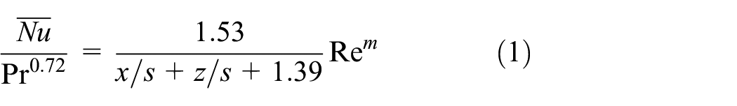
where
Many experimental and numerical studies have investigated various techniques to enhance heat transfer so as to increase the efficiency of the jet impingement based anti-icing system. Use of water jet to study the effect of intermittency on convective heat transfer was investigated by Zumbrunnen and Aziz. 27 Surface pressure and heat transfer characteristics of a round jet impinging normal on isothermal plate were experimentally studied by Tawfek. 28 Many studies have shown that various mechanisms can be used to enhance heat transfer over a larger area such as jet intermittency 29 or increased turbulence.30,31
Zhou et al. 32 suggest use of mesh screens while Hee Lee et al. 33 propose use of perforated plates in between the jet nozzle-exit and impingement surface to enhance heat transfer through increased turbulence. Papadakis and Wong 34 investigated the effect of different parameters on performance of bleed air ice protection systems. Patel and Roy, 35 Zhou and Lee, 36 Saeed, 37 and Fregeau et al. 38 have looked at the effect of different arrangements for an array of hot-air jets. Saeed 37 and Fregeau et al. 38 have suggested development of an extensive data base for numerical correlations to aid in design of anti-icing system 39 through the Kriging-interpolation technique to alleviate the huge computational costs associated with the optimum design of anti-icing systems. The research reported here is therefore also a part of that greater effort to develop a cost effective design methodology for optimizing hot-air anti-icing systems. Use of multiple jets certainly enhances surface heat transfer over a greater area but at the cost of engine performance. The focus of the present study is to use single jet to enhance heat transfer over a greater area by investigating the effect of different geometric and flow parameters.
Two-dimensional heat transfer via hot-jet impingement on a flat plate and the inner leading-edge surface of a modified RAE 2822 airfoil was simulated by Saeed et al. 39 using the commercial CFD software ANSYS Fluent. Numerical simulation of a pair of slot jets impinging on an inclined surface was performed by Patel and Roy 35 to study the effect of jet angle and Reynolds number on the local and average Nusselt. Numerical investigation of convective heat transfer from slot-jets impinging on concave cylindrical surfaces under turbulent and constant heat flux conditions was carried out by Sharif and Mothe. 30
Numerical study of jet nozzle characteristics on impingement cooling of gas turbine blade leading edge 40 indicated that the average Nusselt number at the blade leading edge increases with jet speed but decreases with the distance between the jet nozzle and the pressure side. It was recommended to have a side entry jet which will improve the performance of impingement cooling on turbine leading edge. Fluid flow and thermal analysis for impingement cooling system with a series of air jets have also been reported 41 for varying functional parameters. The results indicated that overall Nusselt number and total entropy generation increases with Reynold number however velocity ratio decreases with channel height. The offset-jet arrangement effects have also been experimentally studied 42 on leading hot-air heating effectiveness of engine inlet guide strut. The improvement in the overall heating effectiveness was attributed to the reduction of normal jet impinging distance and the formation of recirculation flow structure inside the concave cavity. It was also indicated that hot-air heating effectiveness was effected by the normal jet-to-leading edge distance.
Numerical simulation of internal flow in aircraft anti-icing systems with and without inner channel can provide greater insight into the physics and further enhance understanding of the mechanism for improved system performance and enhanced flight safety. Recently, a similar study with focus on the effect of external flow parameters on thermal performance of an inner-liner anti-icing system with jets impingement heat transfer was reported in literature. 4 The present study, however, examines the effects of internal hot-air flow as well as geometric parameters on thermal performance of an inner-liner or channel based anti-icing system with jets impingement heat transfer
The objective of the current study is to study the effect of various flow and geometry related parameters and identify the ones that are more effective in enhancing heat transfer. Therefore, a numerical investigation was carried out using commercial CFD software, ANSYS Fluent, 43 with the objective to study the effect of jet-to-surface height, channel width, channel location as well as jet Reynolds number on heat transfer characteristics so that the best possible arrangement configuration can be identified. In this regards, a curved surface similar to that of a typical wing leading edge, as illustrated in Figure 1, was selected for the numerical analysis. The computational domain comprises of a piccolo tube with a slot from which issues a hot-jet and impinges upon the curved surface representing the wing leading edge.

Sketch illustrating the physical (3D) and the computational (2D) domains.
Numerical modeling using CFD
Modeling of the flow in the internal hot-air region as well as heat transfer simulation was conducted on the commercial CFD software ANSYS Fluent. 43 ANSYS Fluent numerically solves the conservation of mass, momentum and energy equations in a segregated or coupled manner. The mass, momentum, and energy conservation equations for a steady, two-dimensional flow are given by:

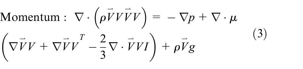
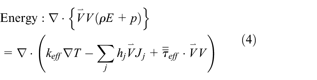
where the first three terms on the right-hand side of equation (4) represent energy transfer due to conduction, species diffusion, and viscous dissipation, respectively.
For the current study, the 2D segregated implicit solver was chosen which sequentially and iteratively solves the conservation equations: first, the momentum equation, then the pressure corrections by continuity equation considering the current pressure and mass flow rate values, and finally the remaining equations including energy, turbulence, and scalar equations are solved till the desired convergence criteria are met. For closure of the turbulence model, additional transport equations are employed. For solid walls, for example the wing surface or impingement wall, only the heat conduction through the wall was calculated.
ANSYS Fluent’s Design Modeler was used to build the physical model of the piccolo tube and associated geometry. Fluent has the capability of generating various types of meshes such as unstructured, structured, and combined meshes in 2- and 3-dimensional domains. For this study, hybrid meshes which involved structuring around the piccolo tube and near the wall, and unstructured mesh in the rest part of the region were used. In order to substantiate the numerical study, grid independence studies were carried out and are presented in a later section. However, an unstructured mesh of approximately 340k cells was found to yield good agreement with the experimental data of Martin. 26 In this study, a total of 48 cases were numerically simulated to study the effect of the jet-to-surface height, channel width, channel location as well as jet Reynolds number. These cases included select combinations of three different jet-to-surface spacings (z/d), five different channel heights (h/d), and five different channel inlet location angles (θ) with respect to the piccolo tube center. The select combinations were analyzed at two different Reynolds numbers. Initially a flat plate computational model, shown in Figure 2, was analyzed and the results were compared with Martin’s 26 empirical correlation. The flat plate computational domain was discretized using a 160 × 100 structured grid as shown in Figure 3.

The computational domain for jet impingement on a flat surface.

Domain discretized using a structured grid for a flat plate model.
Turbulence model study
The flat plate model was simulated with various turbulence models like one-equation Spalart-Allmaras, two-equation Standard K-Epsilon, RNG K-Epsilon, Realizable K-Epsilon, and Standard K-Omega models. The results were compared with the Martin’s empirical data and are presented in Figure 4 where the average Nusselt number (Nuavg) distribution is plotted along the non-dimensional distance parameter x/s. The parameter x/s represents the non-dimensionalized form of the horizontal distance x along the impingement surface (bottom surface in Figure 2) non-dimensionalized by the hot-jet slot dimension (s = 2d, where d is the jet slot diameter). The average Nusselt number is determined from the local Nusselt number through the following relation.


Comparison of different turbulence models run for flat plate.
Comparison of the results predicted by the different turbulence models indicate that two-equation K-Epsilon turbulence models yield higher heat transfer values, with the standard K-omega turbulence model giving the highest heat transfer near the stagnation region. The results of the Spalart-Allmaras turbulence model were found to be in good agreement with Martin’s empirical data. It is a simplified one-equation model which was mainly developed for wall bounded flows in aerospace applications. Being one-equation turbulence model, it allowed simulation of a large number of cases due to its reduced computational time. Thus, the Spalart-Allmaras turbulence model was used in the current study due to the accuracy of its prediction and reduced computational time.
Grid independence study
As mentioned earlier, three meshes were examined: coarse (160 × 100 quadrilateral cells), medium (240 × 150 quadrilateral cells), and fine (320 × 200 quadrilateral cells). The results in terms of average Nusselt number distribution along the surface are plotted in Figure 5 which shows that the fine mesh gave the highest heat transfer while the coarse mesh gave the lowest. The medium mesh results were just slightly lower than the finer one; as a result the finer mesh was chosen so as to improve the accuracy of results. The finer mesh gave a y+ value of 46 which was acceptable since Fluent recommends a value of y+ should be either less than 1 or greater than 30 for the Spalart-Allmaras turbulence model.
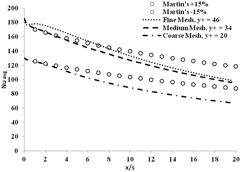
Grid independence study.
Next a curved wall model (Figures 1 and 6) was analyzed with a leading edge profile of the NACA 23012 airfoil. Figure 6 also shows the different non-dimensional variables used to construct the different configurations namely (a) jet-to-target spacing (z/d) of 4, 6, and 8. (b) channel heights (h/d) of 0.4, 0.7, 1.0, 1.4, and 1.8. (c) channel inlet location angle (θ) of 10°, 20°, 40°, and 60° with respect to the piccolo tube center. The channel inlets were placed at an angle of 10° with respect to the hot-air jet axis and care was taken so that as the jet-to-target spacing was varied, the angle remained fixed at 10°. Figures 7 and 8 show the details of the computational domain discretized using a combination of structured and unstructured grids. Figure 8 shows the close-up views of the computational mesh around the hot-jet slot with and without the presence of the etched channel. Again, three meshes were examined: coarse (150 × 246 quadrilateral cells), medium (225 × 372 quadrilateral cells), and fine (300 × 490 quadrilateral cells). The fine mesh size of 300 × 490 quadrilateral cells was used to analyze the different geometric and flow parameters.

The curved wall model illustrating the geometric parameters used in this study.
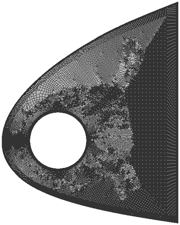
The complete meshed domain for the curved wall model.

Close up view of the mesh with and without the etched channel.
The two-dimensional double precision solver in Fluent was used to simulate all cases. The convergence criterion for the residuals was set at 10−6 for continuity, momentum, and energy terms. A 2.80 GHz Intel i5 Processor desktop with 4 GB RAM was used for all simulations and on an average each case took approximately 36 h to converge. A mesh size of 300×490 quadrilateral cells was used to analyze all the cases. In addition, several passes of grid adaption were also used to ensure that the wall y+ was within the values recommended by Fluent.
Figure 9 shows the different boundary conditions imposed on the curved wall model. A stationary isothermal wall boundary condition was imposed on the impinging wall with a temperature (Twall) of 260 K such as that experienced by aircraft operating under icing weather conditions and exposed to ambient temperature (much lower than the wall temperature) on the other side. The piccolo wall is kept at a constant heat flux with a thickness of 0.002 m. Pressure outlet boundary condition is used to define the static pressure at flow outlets. An added advantage of this type of outlet boundary condition is that it defines scalar variables in case of back flow. The pressure outlet boundary condition requires the specification of static (gauge) pressure at the outlet boundary. Since the outlet conditions are ambient, zero gauge is defined as the pressure for pressure outlet boundary condition. Ambient pressure is defined as the operating pressure. The mass flow rate inlet boundary condition is used to model the flow inlet boundary. Air acting as ideal gas is considered to flow out from a jet with Reynolds number 60,000 (V = 34.959 m/s) and viscosity (v = 1.789 × 10⁻⁵ kg/m s) at 400 K (Tin). Appropriate reference values were set for post processing as shown in Table 1.

The boundary condition for the curved wall model.
Reference values used for post processing.

Results and discussions
The results shown in Figure 10 are the validation results for a flat plate, curved, and channeled baseline model with Martin’s correlation. Since a ±15% spread in experimental data was observed by Martin, both the upper and lower bounds of the empirical results are plotted for comparison with numerical results. In addition, the average Nusselt number (Nuavg) distribution is plotted as a function of the x/s distance along the lower curved surface of the wing profile (the impingement surface). It is mentioned here that since the wing operates at a positive angle of attack during flight and as such the ice accretes on the lower surface of the wing starting around the stagnation point. Therefore, the average Nusselt number (Nuavg) results in this study are presented as a function of the non-dimensional curvilinear distance x/s, starting from the stagnation point where the hot-jet strikes the curved wall or the impingement surface.

Comparison of different numerical models with empirical data.
The validation results show that there is an increase in heat transfer as we move from a flat plate model to a curved surface model, this is due to the effect of curvature which has also been proven by previous researchers like Sharif and Mothe 30 who have suggested that there is a 20% increase in heat transfer in curved model impingement compared to a flat plate model. The curvature is seen to increase the momentum of the wall jet which results in an enhanced heat transfer. Lastly, as a baseline case, the results of the curved model with an inner channel simulated under same conditions is also plotted for reference. The results predict a significant increase in heat transfer up to 20% compared to the curved model and significantly more compared to the flat plate model because of the channel placed at an angle of 10° from the center of the piccolo tube. For the channel case, again increase in the heat transfer can be attributed to increased wall jet momentum close to the inlet of the channel. The increased heat transfer around the stagnation point region can be attributed to the local confinement and circulation due to curvature.
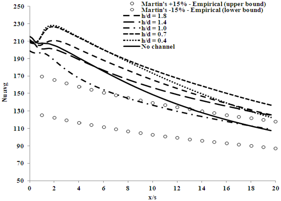
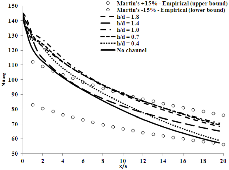
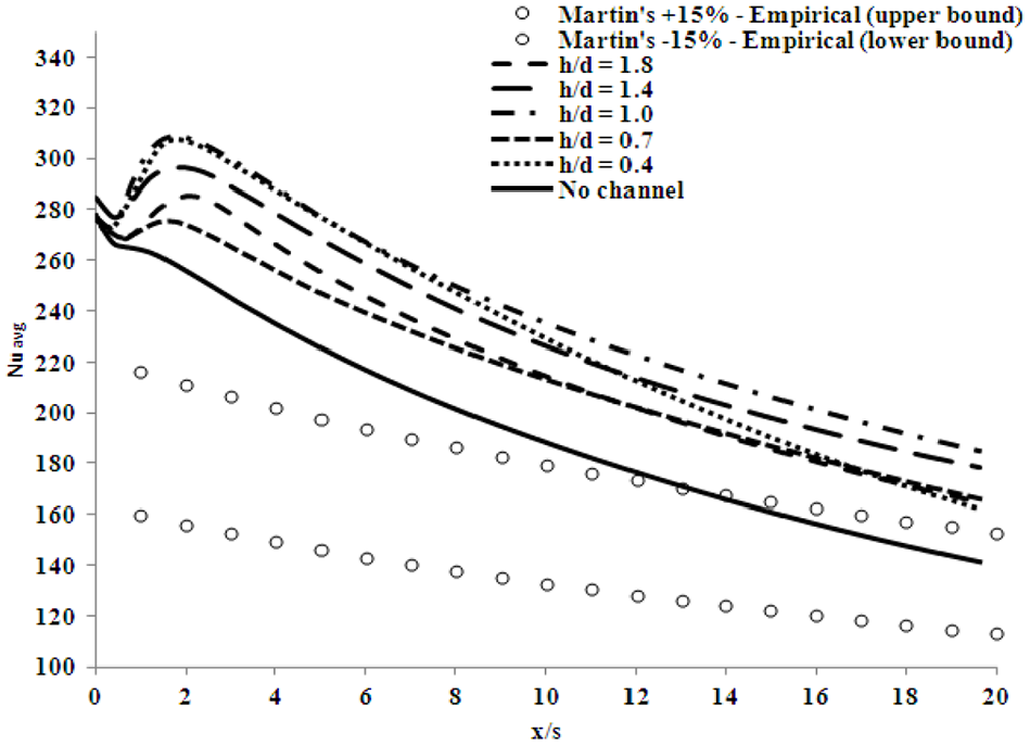
The results for the different jet-to-target spacing (z/d) are shown in Figures 11 to 13 respectively. The results show that heat transfer increases when the jet-to-target spacing is lowered from 8 to 6 and decreases jet-to-target spacing is lowered from 6 to 4 heat transfer. Thus, the results indicate that a jet-to-target spacing of 6 is the optimum in case of impingement on a curved surface. The results also show a peak in heat transfer value around x/s = 2 followed by a gradual fall off with distance from the stagnation point. This fact is attributed to the start of the channel inlet at that location which is seen to impart more momentum to the wall jet region as a result of increased turbulence and shear stress along the impinging wall. The validity of this reasoning is confirmed by the fact that the peak does not appear in the simulation case without a channel.

Results for z/d = 8 for different channel heights.

Results for z/d = 6 for different channel heights.
Results for z/d = 4 for different channel heights.
Livingood and Hyrcak 31 conducted an extensive literature survey of experimental and numerical studies on heat transfer due to jet impingement on flat surfaces. They reported that the optimum jet-to-target spacing for a single circular jet is around 6–7 and for a single slot jet is 8. The present study suggests that the optimum jet-to-target spacing for enhanced heat transfer is closer to 6 for curved surfaces. Moreover, it has been observed that the optimum jet-to-target spacing depends on the presence of a channel and the channel height. The channel height (h/d) of 1.8, the maximum value investigated in this study, at the optimum jet-to-target spacing was observed to yield the highest heat transfer. Further study is needed to determine the optimum value of this non-dimensional channel height (h/d). Based on these results, the jet-to-target spacing of 6 was fixed for all later simulations to determine the optimum channel inlet location angle and the Reynolds number.
Figures 14 to 17 present the effect of channel inlet location angle (θ) on the average Nusselt number Nuave distribution. The simulations were performed for θ values of 10°, 20°, 40°, and 60°. Amongst the 4 channel inlet location angles investigated, the inlet location angle 10° yielded the highest overall heat transfer distribution. The results suggest that the channel should be placed as close to the stagnation region as possible. All the angles were investigated at a jet-to-target spacing z/d of 6 since it gave the highest overall heat transfer distribution. The simulations predicted that as the channel inlet location angle was increased there was a decrease in the value of heat transfer. This can be attributed to the fact that as the distance of the channel inlet increases from the stagnation region, the flow and its momentum entering the channel decreases.

Results for channel inlet placement angle of 10° for different channel heights.

Results for channel inlet placement angle at 20° for different channel heights.

Results for channel inlet placement angle of 40° for different channel heights.

Results for channel inlet placement angle of 60° for different channel heights.
A jet Reynolds study was conducted the results of which are shown in Figures 18 and 19. The effect of jet Reynolds number on Nuavg was simulated for Re values of 30,000 and 90,000 in order to understand how the change in Reynolds number affects the heat transfer on the impinging wall and inside the channels. Martin’s empirical correlation for flat plate for Re = 30,000 and 90,000 are shown for comparison. The result shows that an increase in the jet flow Reynolds number results in a substantial overall increase in heat transfer distribution.
Results for Reynolds number 30,000 at a jet-to-target spacing of 6.
Results for Reynolds number 90,000 for jet-to-target spacing of 6.
Figure 20 shows the effect of channel angle for fixed values of channel height-to-slot diameter value of h/d = 1.0, a jet-to-surface spacing of z/d = 6.0, and a jet Reynolds number of 60,000. The results indicate that as the channel angle is increased, there is an overall decrease in the surface heat transfer from the impingement surface. This can be attributed to the fact that the wall jet region tends to increase away from the stagnation region and therefore less amount of hot-air enters the channel resulting in a decrease in the heat transfer from the impingement wall.

Effect of channel angle (θ).
Figure 21 shows the effect of channel height-to-slot diameter for fixed values of channel angle θ= 10°, a jet-to-surface spacing of z/d = 6.0, and a jet Reynolds number of 60,000. The results indicate that a change in the channel height-to-slot diameter for the optimum jet-to-surface spacing of z/d = 6.0 does not affect the surface heat transfer from the impingement surface. This can be attributed to the fact that the wall jet region is the same for the different channel height-to-slot diameter ratios close to the jet slot, that is at the 10° channel angle and hence yields the same of heat transfer for these select channel height-to-slot diameter ratios.

Effect of channel height (h/d).
Figure 22 shows the effect of jet-to-surface spacing z/d for fixed values of channel angle θ= 10°, a channel height-to-slot diameter value of h/d = 1.0 and a jet Reynolds number of 60,000. The results indicate that a jet-to-surface spacing of z/d = 6.0 yields the optimum surface heat transfer from the impingement surface. This fact has been recorded for jet impingement on flat surfaces as well.

Effect of jet-to-target spacing (z/d).
Conclusions
In this study, a two-dimensional numerical simulation study on heat transfer from a hot-air jet impinging on a curved surface resembling the leading edge of an aircraft wing or the slat of an aircraft wing was successfully carried out using the commercially available CFD software, ANSYS Fluent. The simulation is used to model the different hot-air jet configurations typical of those found in small to medium category commercial transport aircraft employing hot-air anti-icing systems in order to identify key parameters that can yield enhanced heat transfer not only around the stagnation region but also further downstream. The major findings of this study can be summarized as follows:
Use of inner channels in aircraft anti-icing systems employing hot-air jets can greatly enhance heat transfer as compared to the conventional systems without the inner channels thereby improve flight safety
The optimum hot-air jet-to-target spacing is found to be six times the hot-air jet with and without the inner channel.
Critical inner channel heights should be identified for practical considerations. In the present investigation, the best channel height is found to be h/d = 1.8 for the optimum jet-to-target spacing of z/d = 6. The results indicate that a smaller jet-to-target spacing yields better overall heat transfer for smaller channel heights (h/d = 0.4 and 0.7). Similarly, a higher jet-to-target spacing of z/d = 6 gave higher overall heat transfer distribution for higher channel heights (h/d = 1.0, 1.4, and 1.8). Further study is needed to determine the optimum value of this non-dimensional channel height (h/d).
The best location of the inlet to the inner channel with respect to the hot-air jet exit in terms of the channel inlet location angle for the cases investigated suggest that smaller inlet location angle leads to an increase in the heat transfer. Further investigations are needed to determine the optimum location of the channel inlet angle as well as for a better understanding of the underlying physics. This is currently being investigated.
The channel inlet location angle which gave highest overall heat transfer distribution is θ = 10°. In addition, the results indicate that as the channel inlet location angle is increased, heat transfer decreases due to the fact that the distance from the jet inlet to the channel increases and as a result less amount of flow is seen entering the channel.
Increased heat transfer was observed at higher Reynolds number and vice versa.
Footnotes
Appendix
Handling Editor: Chenhui Liang
Author contributions
Farooq Saeed: Conceptualization, methodology, simulation setup, validation. Kamran Z Ahmed: Literature review and numerical simulations. Amro OE Owes: Write-up and editing. Ion Paraschivoiu: Reviewing and editing.
Declaration of conflicting interests
The author(s) declared no potential conflicts of interest with respect to the research, authorship, and/or publication of this article.
Funding
The author(s) received no financial support for the research, authorship, and/or publication of this article.
Research ethics
The authors declare that no human or animal subjects were involved in this work.