
Abstract
Aiming to improve the road friendliness so as to reduce the road damage caused by heavy multi-axle vehicles, and to enhance the ride comfort, we propose a kind of hydro-pneumatic ISD suspension structure, which is equivalent to a two-stage ISD structure integrating a traditional hydro-pneumatic suspension and a fluid inerter. Firstly, based on the 1/4 model, a genetic algorithm is used to optimize the key structural parameters of hydro-pneumatic ISD suspension. Secondly, the AMESim dynamic model of heavy multi-axle vehicles is built for the performance comparison between the traditional hydraulic and hydro-pneumatic ISD suspensions. Finally, this paper machines a hydro-pneumatic ISD suspension to replace the traditional hydraulic one in a heavy multi-axle vehicle to carry out a road test. Test results indicate that the proposed suspension can effectively restrain the vibrations of sprung and unsprung mass and improve ride comfort as well as road friendliness. The hydro-pneumatic ISD suspension can be applied to engineering.
Introduction
The suspension is an important part of the vehicle, and it has a great influence on ride comfort, handling stability, and ride safety.1–3 Traditional passive suspensions are mainly composed of mechanical spring and damper. 4 The hydro-pneumatic suspension system was initially developed by Citroen in the 1950s and then applied to the DS19 model. 5 Later, in the early 1960s, Alex Moulton and Alec Lssigonis proposed the hydrolastic suspension system using rubber as the elastic element, and sealed fluids as bodywork supports. Subsequently, a connected hydro-pneumatic suspension was developed, which used nitrogen instead of rubber to improve the performance, laying the foundation for the development of hydro-pneumatic suspension. 6
In 2001, Smith 7 proposed the concept of inerter and constructed the “Inerter-Spring-Damper” (ISD) suspension structure system.8,9 Yang 10 applied ISD suspension to heavy multi-axle vehicle and their simulation proved that the modified system effectively suppressed the low-frequency resonance of suspension and reduced the road damage resulting from the dynamic tire load, thus significantly improving the ride comfort and road friendliness. 11 However, the “mechanical” ISD suspension has disadvantages such as excessive components and complex structure. In order to address these issues, researchers have made efforts to integrate the hydraulic inerter with other components. Papageorgiou 12 opened a damper hole on the piston of a hydraulic inerter to connect the inerter and the damper, but this is only a two-element fusion design, and fails to achieve the three-element fusion of inerter, spring, and damper.
Based on the studies of hydraulic inerter, 13 this paper integrates traditional hydro-pneumatic suspension and hydraulic inerter to design a new type of hydro-pneumatic ISD suspension. 14 The piston of the hydraulic cylinder pushes the fluid into the helical channel and stores a large amount of kinetic energy with the high-speed flowing fluid, amplifying the inertia of fluid. This new type of hydro-pneumatic ISD suspension is in principle equivalent to the mechanical two-stage ISD suspension,15–18 and is therefore easy to equip on vehicles. Based on AMESim, 19 a 1/4 hydro-pneumatic ISD suspension is constructed for parameters optimization,20,21 and a whole vehicle model is established for performance simulation. Finally, a road test 22 verifies that the hydro-pneumatic ISD suspension can improve the comprehensive performance of heavy multi-axle vehicles, effectively suppressing the vibrations of vehicle sprung and unsprung mass, while improving the ride comfort and road friendliness.
Hydro-pneumatic ISD suspension model
In this paper, inerter, spring, and damper are integrated in the mechanical-hydraulic system to obtain the hydro-pneumatic ISD suspension, which consists of accumulator I, damper valve I, accumulator II, damper valve II, hydraulic cylinder, piston, connecting rod, and helical channel. Figure 1 shows the structure of the proposed system, Figure 2 shows schematic of the equivalent mechanical two-stage ISD suspension. Hydraulic cylinder can be divided into upper and lower chambers by piston: the upper chamber and accumulator I are connected and articulated with spring mass; the lower end of the piston rod is hinged with unsprung mass; accumulators I and II are connected by the helical channel.

Schematic of hydro-pneumatic ISD suspension.

Schematic of the equivalent mechanical two-stage ISD suspension.
In the hydro-pneumatic ISD suspension, the ratio of the effective flow area of the hydraulic cylinder to the helical channel is used to amplify the fluid inertia, which is similar to the inertia principle generated by the hydraulic inerter; the piston drives fluid to move at high speed in the helical channel and stores a great amount of kinetic energy; the hydro-pneumatic ISD uses nitrogen in the accumulator as an elastic element; and the throttle hole is set up at the entrance of the accumulator to act as the damper valve. Using the fluid as the force transmission medium, the inerter fusion, spring, and damper force are designed.
Parameters optimization and modeling of hydro-pneumatic ISD suspension
Modeling and parameters optimization of 1/4 hydro-pneumatic ISD vehicle
In this paper, the basic modules in AMESim hydraulic, mechanical and signal library are invoked to construct a model of 1/4 vehicle hydro-pneumatic ISD suspension, as shown in Figure 3

1/4 model of hydro-pneumatic ISD suspension.
The time-domain formula of filter white noise is used as the model of road excitation input:

In the formula,
As it is necessary to take ride comfort and road friendliness into account when the suspension structure parameters are optimized, a target function containing ride comfort and road friendliness is constructed in AMESim for parameters optimization. The multi-objective optimization problem is transformed into a single-goal optimization problem by linear weighting, and the target function is shown in formula (2).
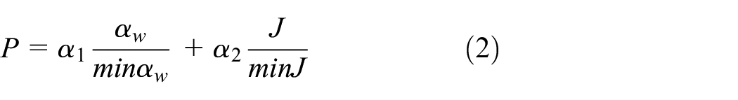


In the formula,
The spring, damper and inerter are adjusted by optimizing the following parameters: the diameter
Main parameters of vehicle.

At a speed of

Comparison of random input response for simulation: (a) BA, (b) SWS, and (c) DTL.

Comparison for values of RMS.
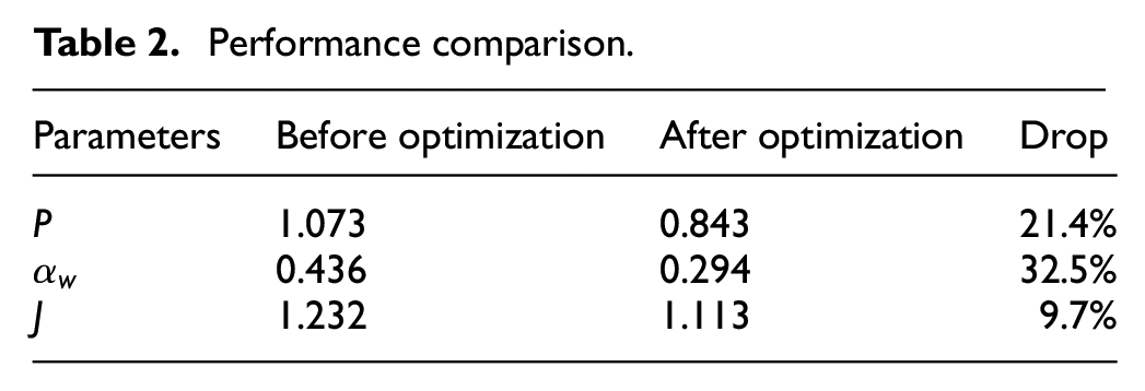
As can be seen from Figures 4 and 5, the hydro-pneumatic ISD suspension after optimization can effectively improve ride comfort and road friendliness. The performance indices before and after optimization are shown in Table 2.
Performance comparison.
Whole vehicle model of hydro-pneumatic ISD suspension
Figure 6 shows the dynamic model of heavy multi-axle vehicle containing hydro-pneumatic ISD suspension, braking, steering and transmission models, etc. Figure 7 shows the road and tire models. The main parameters are shown in Table 3.

Vehicle dynamics model based on AMESim.

Road and tire model.
Main parameters of vehicle.

Simulation analysis of hydro-pneumatic ISD system
Simulation of pulse input
To analyze the vibration isolation performance of the hydro-pneumatic ISD suspension under pulse input, the vehicle is driven past the long waveform bumps as pulse input.
The model of long waveform bump is:

where
In this paper, the BA, SWS, and DTL of the left first and third axles of the trailer are used as performance indices. The performance of the hydro-pneumatic ISD suspension is compared with the traditional hydraulic suspension of heavy vehicles when the vehicle drives over the long waveform bump at a speed of
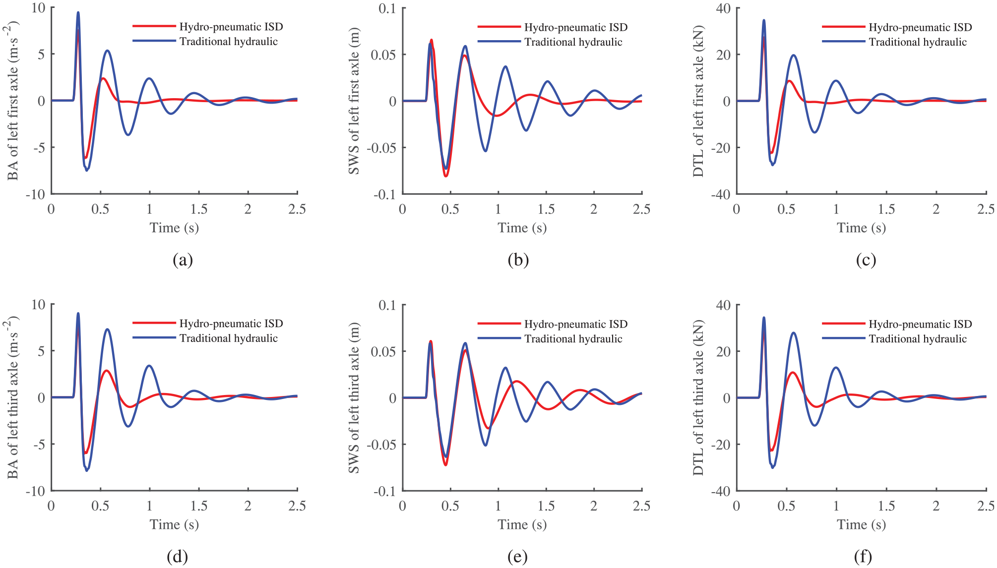
Comparison of pulse input response for simulation: (a) BA of left first axle, (b) SWS of left first axle, (c) DTL of left first axle, (d) BA of left third axle, (e) SWS of left third axle, and (f) DTL of left third axle.
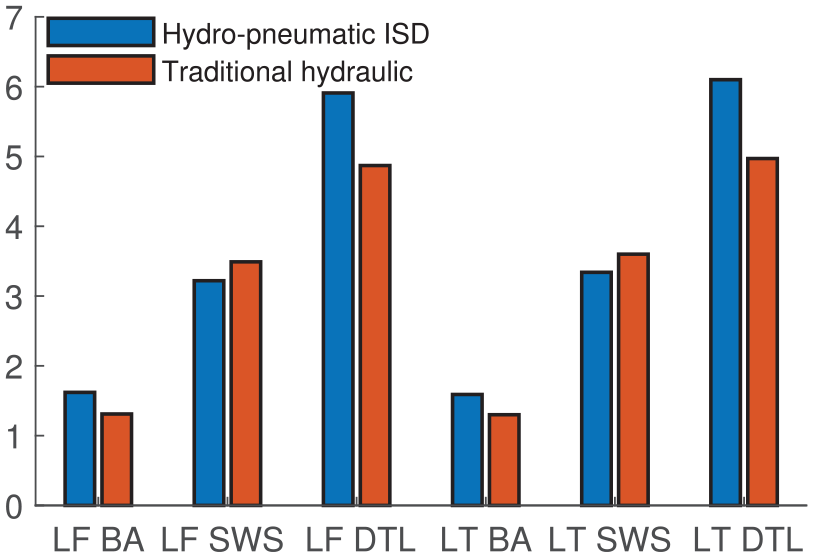
According to Figure 8 and Table 4, compared with the traditional hydraulic, the peak-to-peak (PTP) values of the left BA of the first axle, the left DTL of the first axle, the left BA of the third axle, and the left DTL of the third axle reduced by 19.04%, 19.64%, 19.15%, and 18.81%, respectively, for the time-domain response of the hydro-pneumatic ISD suspension; while, the PTP values for the left SWS of the first axle and the third axle increased by 8.96% and 9.92%, respectively. These data demonstrate that the hydro-pneumatic ISD suspension can effectively suppress body vibration and improve ride comfort as well as road friendliness.
PTP values of pulse input response for simulation.

Simulation of random input
In order to investigate the vibration isolation performance of the hydro-pneumatic ISD suspension under random inputs, the vehicle was driven at a speed of

Comparison of random input response for simulation: (a) BA of left first axle, (b) SWS of left first axle, (c) DTL of left first axle, (d) BA of left third axle, (e) SWS of left third axle, and (f) DTL of left third axle.
Comparison for values of RMS.
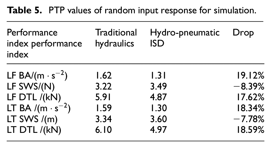
As shown in Figures 9 and 10 and Table 5, both the RMS values of BA and DTL of the hydro-pneumatic ISD suspension are improved, but the RMS values of SWS deteriorate slightly under random input. Compared with the traditional hydraulic suspension, the RMS values for the BA and DTL of the left first axle decreased by 19.12% and 17.62%, respectively, while, the RMS value of SWS increased by 8.39%. As for the left third axle, the RMS values of the BA and DTL decreased by 18.34% and 18.59%, respectively, the RMS values of SWS increased by 7.78%. It can be seen that the hydro-pneumatic ISD suspension can effectively mitigate body vibration, restrain tire beating, and make the most of the suspension working space, thus effectively improving ride comfort and road friendliness.
PTP values of random input response for simulation.
Road test system of hydro-pneumatic ISD suspension
Test system of vehicle
A heavy multi-axle trailer vehicle with hydraulic suspension is selected as the test subject, the model of the vehicle is 9VUL2156 and the VIN is R1PDX3004J1000317, the type of traditional hydraulic suspension that we choose is dual-chamber hydro-pneumatic suspension; the test system of the vehicle is shown in Figure 11; and the parameters of the test vehicle and suspension are detailed in Table 6.

Vehicle test system for hydro-pneumatic suspensions.
Main parameters of vehicle.

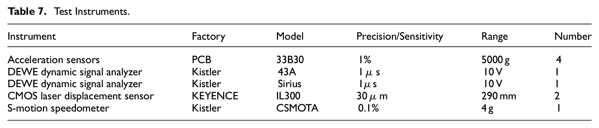
During the road test, four vertical acceleration sensors are arranged at the appropriate positions on the left side of the body and the left axle of the first/third axle for data collection; the S-Motion speedometer is arranged at the centroid of vehicle to collect data on the vertical acceleration of centroid and the acceleration of pitch angle; and the COMS laser displacement sensor is installed on the left side of the first/third axle to collect data on SWS. The data acquisition scheme is shown in Figure 12. And the specifications of the sensors adopted for the experimental measurements is shown in Table 7.

Schematic of data acquisition.
Test Instruments.
Test results and performance analysis
Test of pulse input
The road for the pulse input is a cement pavement with the slope <1%. Due to the specificity of the test vehicle and the restriction of the site, 50 mm × 50 mm blocks are adopted as pulse inputs, and the pulse input test is carried out on
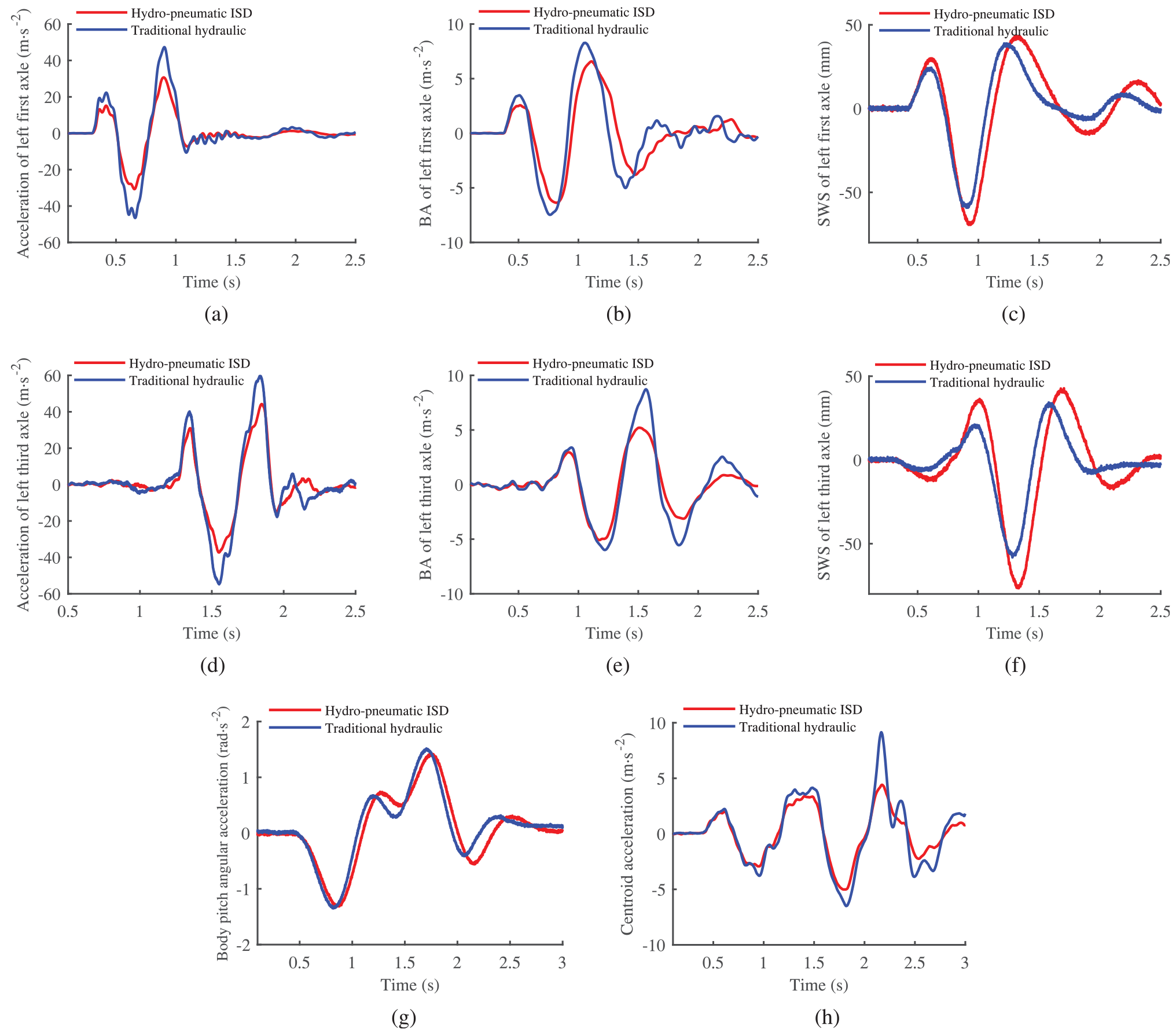
Comparison of pulse input test results: (a) acceleration of left first axle, (b) BA of left first axle, (c) SWS of left first axle, (d) acceleration of left third axle, (e) BA of left third axle, (f) SWS of left third axle, (g) body pitch angular acceleration, and (h) centroid acceleration.
PTP values of pulse input response for simulation.

Figure 13 and Table 8 show that the PTP values of the BA of the left first/third axle, the acceleration of the left first/third axle, the acceleration of pitch angle, and the acceleration of centroid dropped by 17.80%, 34.58%, 30.04%, 28.85%, 4.22%, 39.56%, respectively, compared to the traditional hydraulic suspension. The PTP values for the SWS of the left first/third axle increased by 14.89%, 25.47%, respectively. These demonstrate that the hydro-pneumatic ISD suspensions can effectively attenuate the vibrations of the sprung and unsprung mass, suppress the body pitch, and improve the ride comfort and road friendliness.
Test of random input
The test level for random input is C. For the random input test, the speed of heavy multi-axle vehicle full-load generally does not exceed

Comparison of random input test results: (a) acceleration of left first axle, (b) BA of left first axle, (c) SWS of left first axle, (d) Acceleration of left third axle, (e) BA of left third axle, (f) SWS of left third axle, (g) Body pitch angular acceleration, and (h) centroid acceleration.
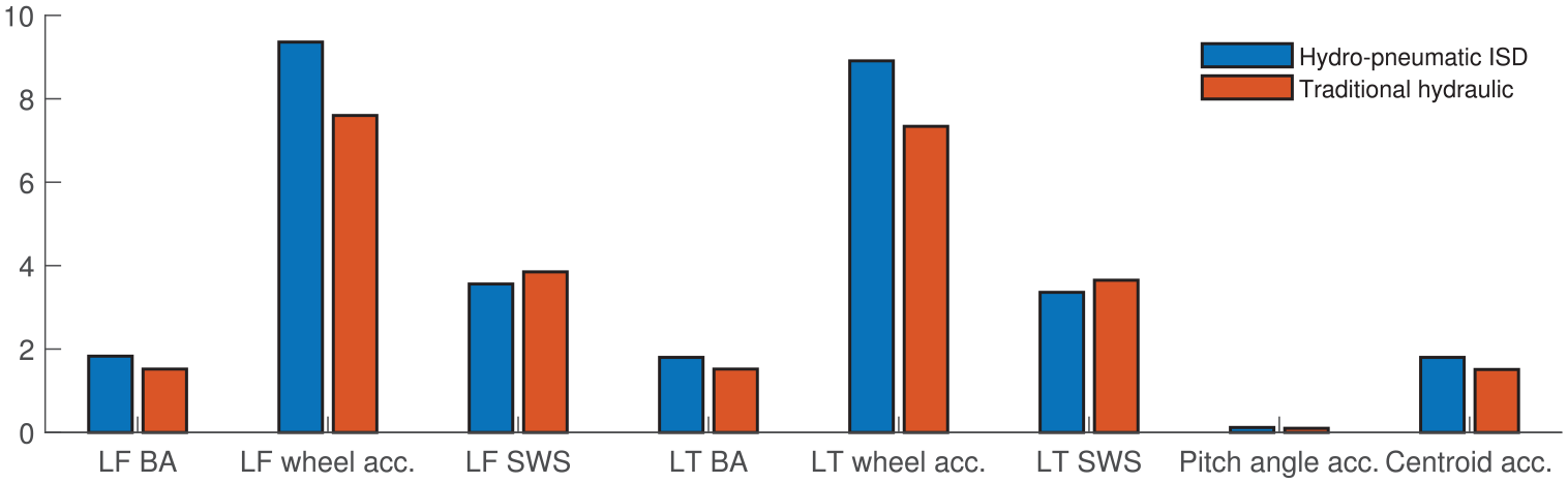
Comparison for values of RMS.
RMS values of random input response for test.
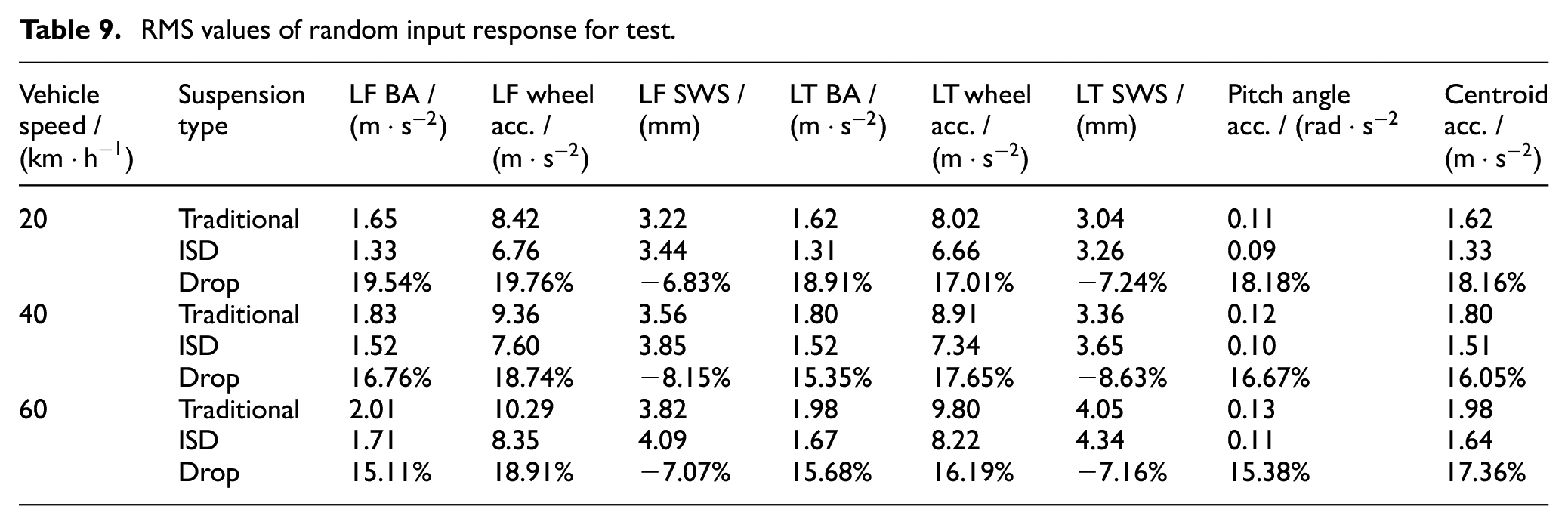
As shown in Figures 14 and 15 and Table 9, at the speed of 40 km/h, compared with the traditional hydraulic suspension, the RMS values for the BA of the left first/third axle, the accelerations of the left first/third axle, the pitch angle, and the centroid decreased by 16.76%, 15.35%, 18.74%, 17.65%, 16.67%, and 16.05%, respectively. The RMS values for the SWS of the left first/third axle increased by 8.15% and 8.63%, respectively. The experimental results show that the hydro-pneumatic ISD suspension can effectively attenuate the vibrations of the sprung and unsprung mass, restrain the body pitch, and significantly improve the ride comfort and road friendliness of the heavy multi-axle vehicles.
Conclusions
Based on AMESim, the model of hydro-pneumatic ISD suspension vehicle is established, and the performance difference between the new and traditional hydraulic suspensions is studied. The simulation results show that the proposed suspension can significantly restrain the vibrations of the body and wheels, improve the comprehensive performance of the vehicle, verifying the feasibility, and effectiveness of the hydro-pneumatic ISD suspension engineering scheme.
With a heavy multi-axle vehicle as the test object, a hydro-pneumatic ISD suspension system is manufactured and installed on the test vehicle; the tests of pulse and random inputs were carried out. The test results show that the hydro-pneumatic ISD suspension can effectively improve the comprehensive performance of heavy multi-axle vehicles, restrain the vibrations of sprung mass and unsprung mass, thus significantly improving the ride comfort and road friendliness. The proposed suspension can be applied in engineering. In the future study, we will establish a mathematical model by combining the non-linear characteristics for matching the structural parameters of the hydro-pneumatics ISD suspension structure, which will be based on the vehicle performance. The designed model will guide the matching, design, and development of the suspension and the vehicle.
Footnotes
Handling Editor: Ms. Chenhui Liang
Declaration of conflicting interests
The author(s) declared no potential conflicts of interest with respect to the research, authorship, and/or publication of this article.
Funding
The author(s) disclosed receipt of the following financial support for the research, authorship, and/or publication of this article: This work was supported by the National Natural Science Foundation of China (Grant nos. 1805223, 51875257 and 51805223), the Jiangsu Government Scholarship for Overseas Studies (Grant no. JS-2019-192).