
Abstract
A generalized method for the meshing analysis of conical worm drive is proposed, whose mathematical model is more general and whose application scope is expanded. A universal mathematical model, which can be conveniently applied to left-handed and right-handed conical worm pairs and their tooth flanks on different sides, is established by introducing the helical spin coefficient and tooth side coefficient of the conical worm. The pressure angle at the reference point, which is a key parameter for calculating the curvature parameters and lubrication angle, is determined based on the unit normal vector of the worm helical surface and is no longer determined by the tooth profile angle in the worm shaft section. The above improvement breaks away from the limitation of the classic meshing analysis method based on the reference-point-based meshing theory and thus expands its application scope. The toroidal surface enveloping conical worm drive is taken as an instance to illustrate the proposed method and the numerical example studies are conducted. The approaches to determine the reference point, the normal unit vector, and the curvature parameters at the reference point are all demonstrated in detail. The numerical results all manifest that the method presented in the current work is correct and practicable.
Introduction
Conical worm drive is a type of cross-axis offset gear transmission, which is composed of a worm and a face worm wheel whose indexing surfaces are both conical surfaces.1,2 The reasonable use of the spatial meshing field makes the conical worm drive possess a series of excellent meshing characteristics. For this, the conical worm drive has attracted many scholars to conduct research on it and some new toothed conical worm pairs have been proposed, such as Spiroid gear or Archimedes conical worm drive, 1 the involute conical worm drive,3,4 and the enveloped conical worm drives,5–7 as shown in Figure 1.
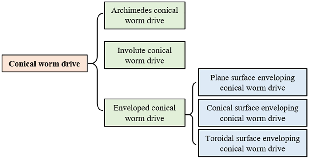
The classification of conical worm drives.
As is well known, meshing analysis is an important means to evaluate the meshing performance of the gear drive. For the conical worm drive, there are two typical kinds of meshing analysis method in the existing literatures,6,7 one is the method strictly based on the tooth surface equations while the other is the method based on the classic reference-point-based meshing theory.8–12 Among them, the former method is strictly based on the solution of the tooth surface equations to obtain the numerical results of the meshing characteristic parameters. In the whole process, the calculation of the geometrical parameters of the worm pair is not involved. Therefore, this method usually cannot intuitively reflect the potential relationship between the meshing characteristics and the geometric design of the conical worm pair. For the latter method, in the calculation process, the key geometric parameters of the reference cone corresponding to the conical worm pair can be obtained, and based on this, the meshing characteristic parameters of the conical worm pair at the reference point are calculated.
As is well known, the main idea of the classical reference-point-based mesh theory was proposed by E. Wildhaber and was applied to the geometric design and the cutting setting calculation of the hypoid gear primarily.13–15 This is a huge advancement in the theory of gear mesh and provides a theoretical basis for the study of staggered shaft gearing. While this theory had not been elaborated detailedly and systematically in a period of time, so a lot of exploration and research works were carried out on it.
In 1961, Baxter 16 studied the design of the reference cones of the hypoid gear.
Since the 1970s, Litvin11,17–19 researched the geometry and mesh principle of the hypoid gear drive. Specifically, the main idea of the classical gear mesh theory based on the reference point is expounded.
Dong9,10 conducted a comprehensive study on the gear mesh theory based on the reference point. The radius design of the cutterhead was proved rigorously and a new calculating formula of the induced normal curvature at reference point was derived. These works make the classic theory suggested by E. Wildhaber more rigorous and can also be applied to the curvature analysis of Spiroid drive.
Almost at the same time, Zeng 12 conducted a rigorous mathematical demonstration of the idea proposed by E. Wildhaber and applied it to the design and manufacture of the spiral bevel gear. More innovatively, the blank design and cutting calculation of the spiral bevel gear are attributed to the calculation of the parameters and the curvature at the reference point of an aligned hypoid gear in his work.
But for the meshing analysis method based on the classic reference-point-based meshing theory, its application objects are relatively limited at present. The reason is that the classic reference-point-based meshing theory has some problems shown as below:
In the classic theory, the reference point was determined by the geometric relationship of the reference cones and some assumptions rather than by the rigorous tooth surface equations. In essence, this is an approximate method because it cannot guarantee that the reference point is actually located on the tooth flank without the strictly limited of the tooth flank equations. As a result, the meshing features of the corresponding conical worm pair at this reference point may not be investigated accurately.
The classical theory can only be applied to the conical worm with linear tooth profile because the pressure angle at the reference point always is approximately calculated with the assist of the tooth profile angle in the worm’s shaft section, which is inconvenient for some types of conical worms with non-linear tooth profile in their shaft section, such as the involute conical worm drive and the enveloped conical worm drives. Because of the above reason, the application scope of the classical theory is limited to some extent.
Lately, Ref. 6 put forward a new method to calculate the reference point and solve the problem (i) mentioned above. However, this work did not mention the reference cones and its related geometric parameters, and the problem (ii) is also not involved.
In the current work, a generalized meshing analysis method combining the methods based on tooth surface equations and the reference point-based meshing theory is presented, which is to solve this problem (ii) with the aid of the unit normal vector of the conical worm helicoids determined by the tooth surface equations to compute the pressure angle at the reference point, thereby the dependence of the existing method on the tooth profile angle in the shaft section of the conical worm is avoided. Besides, the rotation coefficient and tooth surface coefficient are introduced, and then a general mathematical model is established based on this. The above work effectively expand the application scope of the existing method. In order to verify the effectiveness of the method proposed in this paper, the toroidal enveloping conical worm drive has been studied as an application object, and some new characteristics of this type of conical worm drive have been discovered.
Generalized meshing analysis method of conical worm drive
Frames based on reference cones
In the reference-point-based meshing theory, a pair of reference cones can be established based on a set of rules after the reference point is determined, and then the relevant research can be carried out, such as determining the dimension of worm wheel blank based on the dimension of worm blank, and calculating the meshing characteristic parameters of conical worm pair.9,11,20
For the sake of illustration, the conical worm and the conical worm wheel in mesh are marked as gear 1 and gear 2 respectively. In order to obtain a high transmission efficiency, the rotation directions of the two gears should be different. In other words, when the gear 1 is left-handed, the gear 2 should be right-handed, and vice versa.
As shown in Figure 2, two immobile frames

Reference cones formed based on the reference point: (a) reference cones of the left-handed gear 1 and the right-handed gear 2 and (b) reference cones of the right-handed gear 1 and the left-handed gear 2.

Coordinate systems on the reference cone corresponding to the left-handed gear 1.

Coordinate systems on the reference cone corresponding to the right-handed gear 2.

The coordinate frames for the curvature analysis at the reference point.
Basic geometric parameters
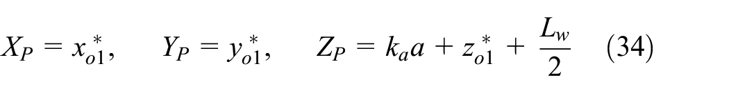
Mathematically speaking, the reference point P in the frame σ can be represented as

where XP, YP, and ZP respectively represent the coordinate components of P in σ.
By the coordinate conversion from the frame σ to σo2, the radius vector

where
Based on equation (2), the dividing circle radius of the gear 2 at the reference point P can be obtained as

It can be seen from equation (3) that when the values of the center distance and shaft angle of the conical worm pair are given, the value of dividing circle radius of the conical worm wheel will be determined by the coordinate values of the reference point.
See Figure 3, the closed angle η1 between the forward direction of

Similarly, the angle η2 between the forward direction of
In a general way, it can be supposed that the gear 1 spins on its axial line at the palstance

As displayed in Figure 2,

where

On the grounds of the geometric positional relationship shown in Figure 3, the basal vector

As shown in Figure 3, the relative velocity vector

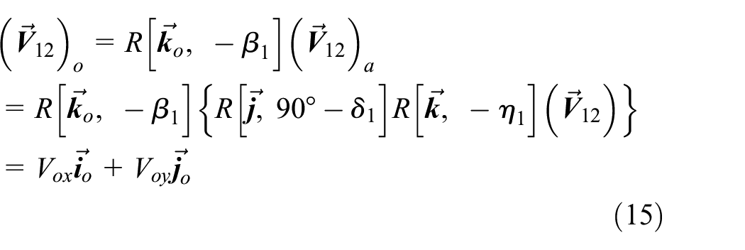
By the coordinate transformations, the relative velocity

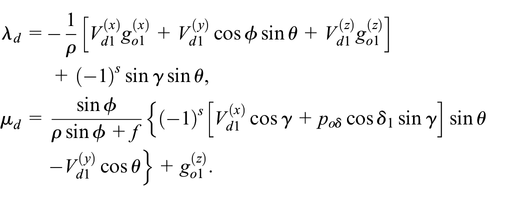
where

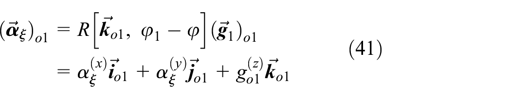
Undoubtedly,

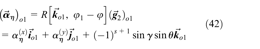
Equations (9) and (12) both manifest that when the position of the reference point changes, the semi-cone angles δ1 and δ2 may be also changed. Taking into account the actual physical meaning, both δ1 and δ2 should be acute angles.
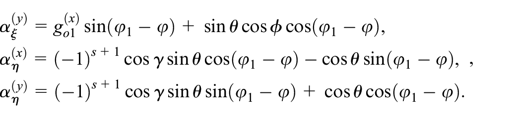
As shown in Figure 3, the vectors


Similarly, the spiral angle β2 in Figure 4 can be determined as
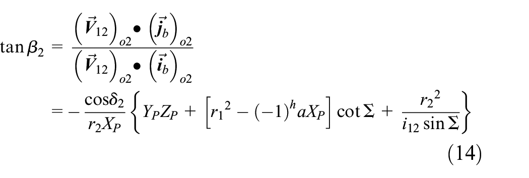
where

Considering the actual physical meaning, the obtained calculated results of equations (13) and (14) should be consistent with the following geometric facts. For the left-handed gear 1 and the right-handed gear 2, the value of β1 is negative but the value of β2 is positive. For the right-handed gear 1 and the left-handed gear 2, the value of β1 is positive but the value of β2 is negative. Besides, when the position of the reference point changes, the values of β1 and β2 will also change.
By the coordinate transformation,
where

Parameters for meshing analysis
After determining the geometrical parameters based on the two reference cones, the curvature relationship between the tooth surfaces of the conical worm and concial worm wheel in mesh at the reference point can be investigated, and then the related meshing characteristics can be evaluated. 9 In the current section, the local meshing characteristic parameters at the reference point, including the induced principal curvature and the lubrication angle, will be determined on the basis of the above calculations and the related theoretical background.
As exhibited in Figure 5, a coordinate system
Since the conical worm and the concial worm wheel are in mesh at the reference point, it can be received that

in particular, when S = 0, equation (16) denotes the
As a key parameter to determine the normal vector
From Figure 2, the normal unit vector

where
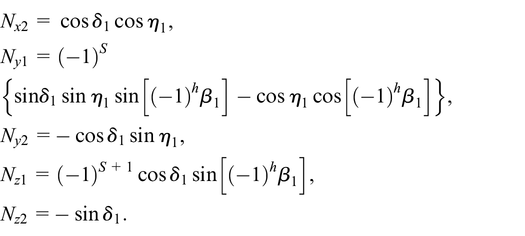
Since

where
Since α n is an acute angle, it can be determined as
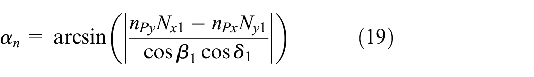
From equation (19), it can be seen that the calculation of the pressure angle
In line with the gearing mesh theory, then the meshing limit function at the reference point can be received as 9

where
Actually, equation (20) can be used as a basis for judging whether the meshing limit line exists in the meshing area. If
By definition, the limit function of the curvature interference can be written as 9

where
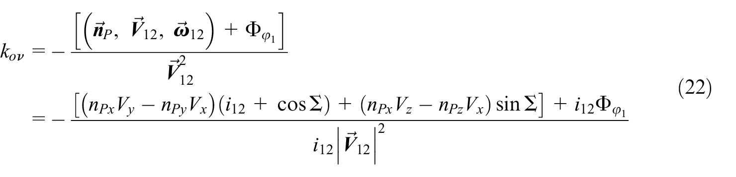
From equation (21), since the relative speed of the worm gear is usually not equal to 0 for the worm gear in mesh, the judgment of whether the curvature interference limit line exists can be attributed to the judgment of whether
On the grounds of the geometric relationship displayed in Figure 5 and based on equation (16), the basal vector

where

Based on the above theoretical derivations, the induced principal curvature between the tooth flanks of conical worm and conical worm wheel at the reference point can be obtained as

Then, the sliding angle of the two gears at the reference point can be obtained as

Pre-determined parameters for meshing analysis of toroidal surface enveloping conical worm drive
The current section is intended to provide the parameters which are required in the method mentioned above when performing the meshing analysis of conical worm drive, including: the coordinate components of the reference point and the normal vector of the tooth surface of the conical worm, and the curvature parameters along the direction of the relative velocity of the concial worm pair at the reference point. In this process, the toroidal surface enveloping conical worm is taken as the gear 1 and the conical worm gear is regarded as the gear 2. Consistent with the above theoretical derivation, the following calculations are comprehensive and can be applied to both the left-handed conical worm and the right-handed conical worm.
Determination of normal unit vector
and reference point P
As described in Ref.,
7
the toroidal surface enveloping conical worm helicoid is ground by the discoid abrasion wheel with the working torus, and the vector equation of the working torus, Σd, can be obtained in

where
In the course of generating the toroidal surface enveloping conical worm, four coordinate frames

Frames in the course of cutting engagement of toroidal surface enveloping conical worm: (a) left-handed toroidal surface enveloping conical worm and (b) right-handed toroidal surface enveloping conical worm.
As displayed in Figure 6, the frames
Based on the transformation of frames, the normal unit vector of the conical worm helicoid in
where

the coefficient S is used to distinguish the tooth flanks of concial worm. When S = 0, the related formulas in this paper corresponding to the tooth surface toward to the toe of conical worm, which can be named as i flank. When S = 1, all the formulas indicates the tooth flank toward to the heel of conical worm, which can be called as e flank.
Since the frames


Coordinate systems in the engagement course of toroidal surface enveloping conical worm drive: (a) left-handed worm and right-handed worm gear and (b) right-handed worm and left-handed worm gear.
By the gear geometry, the meshing function of the cutting engagement of toroidal surface enveloping conical worm can be obtained as follows9,22

where

By Olivier’s second principle, the roll cutting procedure of the worm wheel and the engagement course of the toroidal surface enveloping conical worm pair can be investigated without differentiating. 11 During the meshing process of the worm gearing, the conical worm revolution angle is marked as φ1, meanwhile, the corresponding angle of rotation of the worm wheel is symbolled as φ2 and φ2 = φ1/i12, where i12 is the transmission ratio of the conical worm gearing in question.
In

where

On the basis of equation (8), the relative velocity of the conical worm and the coupled worm wheel can be acquired in
where

By definition, the engagement function of the toroidal surface enveloping conical worm pair can be derived and the outcomes are provided as 23
where
As demonstrated in Figure 8, a plane coordinates
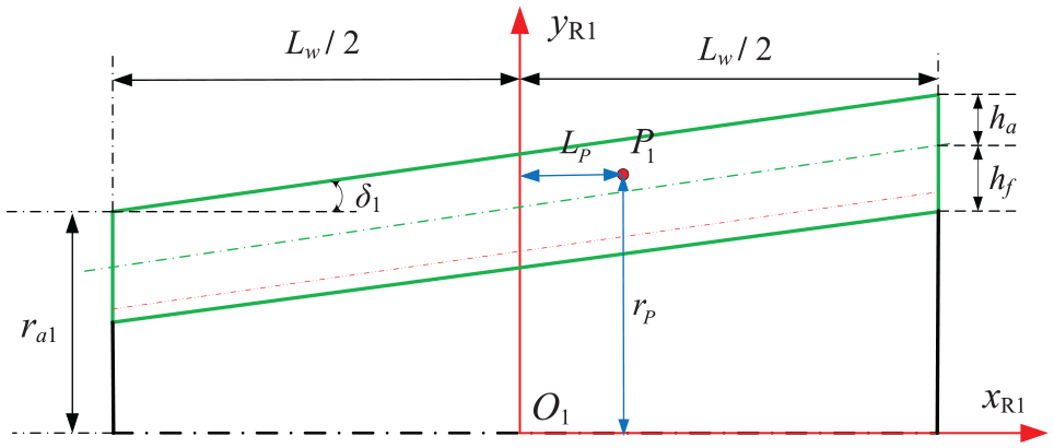
The reference point in the worm shaft section.
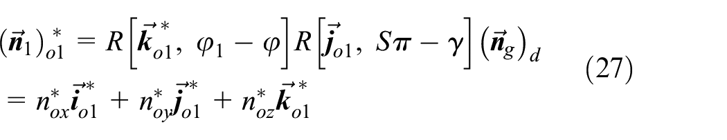
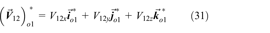
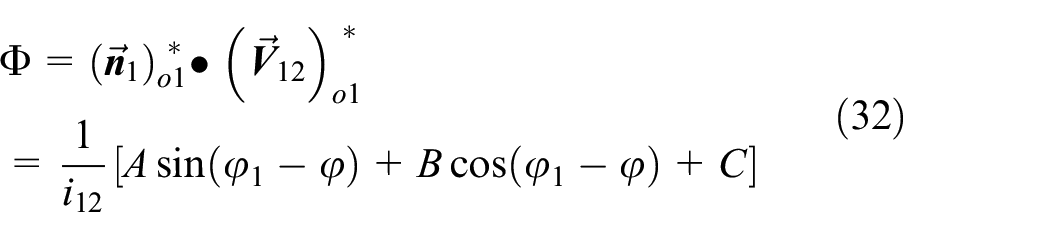
By the geometric site displayed in Figure 8, the reference point P1 on the worm screw may be determined by the non-linear equations of tooth surfaces as shown below

After solving equation (33) iteratively, the tooth surface parameters of the point P1 will be acquired, and then its coordinates in
Determination of curvature parameters along the direction of
A Cartesian space


In the course of grinding the toroidal surface enveloping conical worm, the vectors


where

According to the gear engagement theory, the limit function of curvature interference in the course of the grinding engagement can be obtained as 9
where
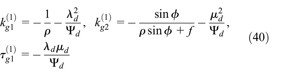
On the grounds of the above results, the normal curvatures along
During the process of the engagement of the worm pair, a frame
where
As shown in Figure 9, the included angle φν between


Frames for computing k1ν and τ1ν in the plane T.
According to the generalized Rodrigues formula,
10
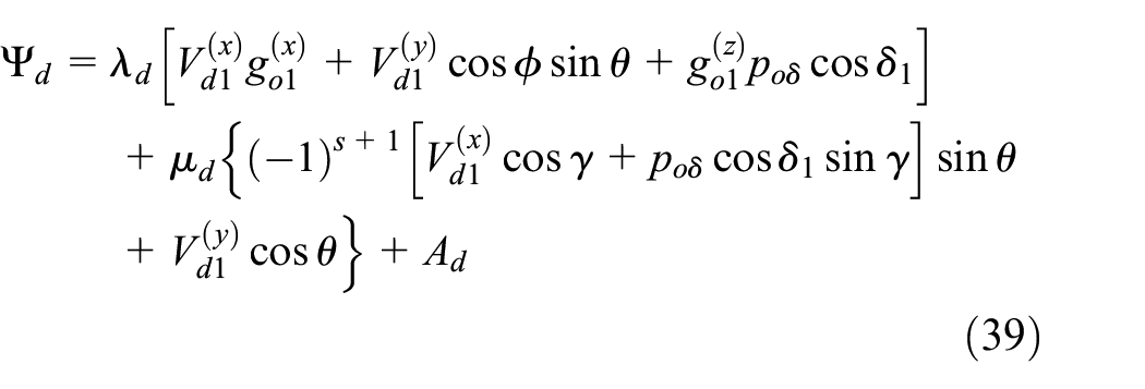
the normal curvature and the geodesic torsion of the conical worm helicoid along

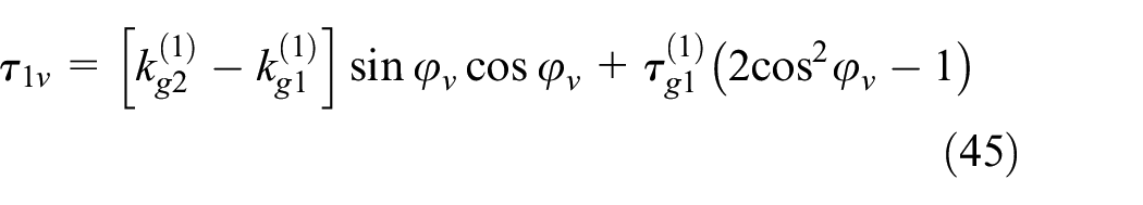
With the aid of equations (44) and (45), the value of
Numerical example investigations
Four numerical examples are provided to verify the correctness of the method suggested in this work and to explore some characteristics of the toroidal enveloping conical worm drive. Concretely, the examples ① and ③ both indicate the worm pair combined by the left-handed conical worm and the right-handed worm gear, ① represents the i flank of the worm pair, and ③ represents the e flank of the worm pair. Similarly, the examples ② and ④ are used to indicate the worm pair combined by the right-handed conical worm and the left-handed worm gear, ② represents the i flank of the worm pair, and ④ represents the e flank of the worm pair. The major parameters of the worm drives are provided in Table 1.
Basic parameters of conical worm pairs.

Computed results and discussion
The numerical results provided in this section mainly include two parts: the first part is used to verify the proposed method (Tables 2 and 3), and the second part is used to study the characteristics of the toroidal enveloping conical worm drive (Table 4).
Numerical results of different methods.

Numerical results of major parameters at reference points.

Major parameters at reference points.

Table 2 provides the numerical results of the major parameters at the selected reference point on the tooth surface of the worm in these examples. For Examples ① and ②, the reference point at the tooth top of i flank on the toe of the conical worm. For Examples ① and ②, the reference point at the tooth top of e flank on the toe of the conical worm. These data were obtained respectively using three different methods, namely: Method a indicates the traditional method based on the reference-point based meshing theory,8–12 Method b represents the method based on the tooth surface equations,6,7 and Method c represents the generalized method suggested in this paper.
Since Method b is strictly based on the tooth surface equations, mathematically, the calculation results obtained based on it can undoubtedly be used as a standard to measure the accuracy of the calculation. As listed in Table 2, the calculated results of the related parameters acquired by Method a are all significantly different from that by Method b, especially in the e flank of the conical worm. This means that Method a maybe inaccurate and inapplicable to the toroidal enveloping conical worm drive. At the same time, it can be seen that the numerical results calculated by Method c are completely consistent with those obtained by Method b, which can prove that Method c is effective.
In Table 3, P1 represents the reference point at the tooth top of i flank on the toe of the conical worm, and P1′ represents the reference point at the tooth top of e flank on the toe of the conical worm. The numerical results provided in Table 3 reflect that the value of parameters at the reference point have nothing to do with the rotation directions of the conical worm pair, in other words, the meshing characteristics of the worm pair have nothing to do with its rotation directions, which is consistent with the recognized guideline in the gear community. The above facts also reflect that the generalized method proposed in this paper is correct and applicable.
Table 4 provided the numerical results of the parameters at the reference points P1, P2, and P3 on the tooth surface of the conical worm in Example ①, the point P1 on the tooth crest at the toe of the conical worm, the point P2 on the tooth crest at the middle of the conical worm, and the point P3 on the tooth crest at the heel of the conical worm.
According to the data displayed in Table 4, the value of r2 decreases gradually from P1 to P3, which is consistent with the characteristics of the geometric structure of conical worm gear. The values of δ1 and δ2 at these reference points are all different from the values of δ1′ and δ2′ in Table 1, it means that the reference cones are actually different from the index cones of the conical worm pair. The value of the helix angles at these points are all different. This shows that the toroidal enveloping conical worm drive is a type of worm drive with variable helix angle, which is obviously different from the cylindrical worm drive. According to the value of pressure angle
Conclusions
The meshing analysis method of the conical worm drive has been generalized, which is embodied in the following aspects:
The pressure angle at the reference point is computed based on the normal unit vector acquired by the tooth surface equations. Compared with the calculation method in the classical theory, the generalized method is no longer limited by the tooth profile shape of the worm and the numerical results calculated by it can be more accurate.
A more universal mathematical model for meshing analysis has been established by introducing the helical spin coefficient and tooth side coefficient of the conical worm. It not only can be directly applied to the conical worm gearing with different rotation directions, but also can be conveniently used to the different tooth flanks of worm pair.
Based on the above results, not only can the geometric parameters of reference cones and worm wheel be accurately calculated, but also the meshing analysis can be implemented precisely at any point on the tooth surface of conical worm pair. Besides, the new method also can easily determine whether the meshing limit line and the curvature interference limit line exist on the tooth surface of the conical worm pair or not. Compared with the method based on tooth surface equations, the generalized method can avoid solving the complex nonlinear equations of tooth surfaces.
The toroidal surface enveloping conical worm pair is taken as the instance to illustrate the generalized method. The approaches to compute the pre-determined parameters for the meshing analysis based on the generalized method are illustrated. Since the method suggested in this paper is a purely analytical method that has nothing to do with the tooth shape of the conical worm, these strategies are theoretically applicable to other types of conical worm drives. Based on the generalized method, the values of the related parameters are calculated. At the same time, some comparison calculations are also provided. These results manifest that the generalized method presented in the current work is correct and practicable. Besides, some characteristics of the toroidal surface enveloping conical worm drive are also discovered.
Footnotes
Appendix
Handling Editor: Chenhui Liang
Declaration of conflicting interests
The authors declared no potential conflicts of interest with respect to the research, authorship, and publication of this article.
Funding
This work was supported by Liaoning Province Doctoral Research Startup Fund (Grant No. 2021-BS-164), Science and Technology Research Projects of Education Department of Liaoning Province of China (Grant No. LJKZ0264), High-level Talent Research Support Program of Shenyang Ligong University (Grant No. 9682), Shenyang Ligong University Scientific Research and Innovation Team Building Project (Grant No. SYLU202101), and National Natural Science Foundation of China (Grant No. 52075083).