
Abstract
Hydrostatic bearings are superior in terms of their friction and load carrying characteristics when compared to contact based bearings, but non-usable in applications with non-constant curvature counter surfaces. A possible solution to this limitation is the introduction of deformable hydrostatic bearings components that cope with these required deformations. To reduce the required deformation of a single bearing pad, multiple pads can be connected through a so-called whiffletree support system. In this work, a symmetric whiffletree based hydrostatic bearing embodiment is introduced. A 2D quasi-static model is introduced that allows for determining the kinetostatic and path following properties of such a type of bearing. Design considerations are given regarding the joint rotational-, normal-, and shear stiffness of each individual joint, as well as basic bearing layout. The potential of a whiffletree suspended bearing is presented through the use of a case study.
Introduction
Hydrostatic bearings have the property of obtaining a high load capacity while maintaining low friction. This is due to the small fluid film between bearing and counter surface. Compared to conventional slider and roller bearings in terms of friction, wear, and load capacity, hydrostatic bearings are the better option. However, conventional hydrostatic bearings are limited to applications that have an external pressure source and constant or zero curvature counter surfaces. 1 To eliminate the second limitation, compliant hydrostatic bearings could provide a solution. Compliant hydrostatic bearings offer the ability to deform, following the counter surface while maintaining its desired constant film height. One approach to design compliant hydrostatic bearings, is to design the support to be elastic. This has been used to counter waviness of the counter surface,2,3 to maintain load capacity when the bearing is tilted 4 or to function as an elastic pivot. 5 However, these type of supports are generally limited to small deformations in the order of the bearing film height.2,6 This results in an absence of hydrostatic slider bearing use in applications with non-constant curvature counter surfaces. Examples of such potential applications can be found in motors and pumps, in civil structures like lock gates, and in sliding rooftops of stadiums.3,7,8 A wide variety of potential applications could thus benefit from improved path-following functionality. This work will focus on the design of a large deforming hydrostatic bearing able to follow a non-constant curvature counter surface.
For hydrostatic bearings it is fundamental that the bearing and the counter surface remain close to parallel. 9 This means that, for a non-constant curvature counter surface, the bearing needs to deform to maintain a parallel orientation with respect to the counter surface. It is expected that the required deformation of the bearing, in order to maintain a parallel orientation to the counter surface, decreases as the length decreases. This is expected, as the curvature of the counter surface becomes close to linear if the length of the curvature decreases. However, a decrease in bearing length results in a decrease in load capacity which is undesirable for most applications. A solution could be to connect multiple smaller bearing pads, also called slipper, together by the use of a support structure. 10 This way, the deformation required from each slipper to maintain a close to parallel orientation with the counter surface, is reduced while load capacity could be maintained. A possible suitable support system is the whiffletree. 11 Examples of applications that use a whiffletree as support are dual-arm manipulators and telescopes.11–14 It is important that conventional contact-based joints are not used in the support system of the hydrostatic bearing since they would re-introduce wear, friction, and backlash into the system. Hydrostatic spherical joints 15 or compliant joints16,17 could solve these drawbacks, providing the same motion as conventional contact joints without these negative properties, 18 although in the case of compliant joints this generally comes at the cost of load capacity. 16 For the design of such a complete whiffletree based system, knowledge is needed about the kinematics and kinetostatics such that the potential quasi-static performance can be defined.
Previous research has shown that the use of elastic support systems allow hydrostatic bearings to follow surfaces with non-constant curvature.2–6 In this previous work it was concluded that elastic supports do improve the deformability of hydrostatic bearings but only for deformations with an order of magnitude of the nominal film height. The contribution of this work is to design a support system that allows deformations orders of magnitude larger than the nominal film height.
In this paper, a symmetric whiffletree based suspension for deformable hydrostatic bearings is introduced. A 2D quasi-static model based on rigid body mechanics is presented that can be used to define the general kinematics, more specifically the rotational requirements for individual joints. Design steps are provided to determine load capacity, normal stiffness, rotational stiffness, shear stiffness, and pressure profiles of such symmetric whiffletree based bearing systems. The model is then implemented in a case study to show the potential of these type of supports.
Methods
The 2D whiffletree based large deforming hydrostatic bearing is presented in this work as an alternative to compliant support bearings as shown in Figure 1. In literature,
1
large deformable bearings are defined as bearings that (a) are able to deform


Elasto-hydrostatic bearing in its deformed configuration to remain parallel with the counter surface (top) and a whiffletree supported hydrostatic bearing in its deformed configuration to remain parallel with the counter surface (bottom).

Single slipper compressed to remain parallel to the track with the corresponding parameters.
where

where

where

Next, the specific track section is rotated such that the gradient of the track at position

where

where

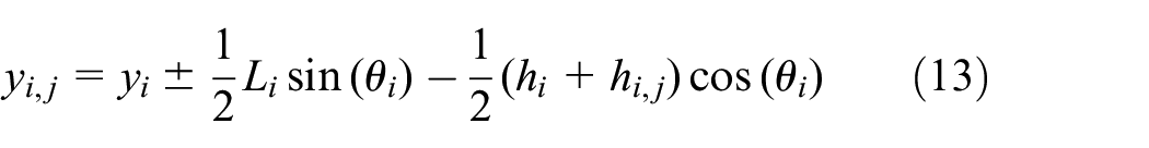
Finally, the linear compression

where

Compression required of a single slipper, as function of the slipper length for a counter track with an amplitude of
Bearing topology
Different embodiments can potentially be envisioned for these kind of support systems. The advantages for implementing these suspensions in hydrostatic bearings is that they allow for the implementation of discrete rotational components, specifically designed for the load case, while simultaneously distributing the load over the support. This, combined with the type of sinusoidal counter tracks investigated in this work, directly impact the topology. The following statements are made concerning the suspension topology investigated in this work:
The suspension will be used to follow symmetric variable counter surfaces.
The suspension will be used to fully distribute the load uniformly.
The first statement directly relates to the definition of using a sinusoidal wave as the basis for counter surfaces, and thus the expected type of deformations. Using both statements, this work introduces the symmetric whiffletree suspension that can be seen in Figure 4 that will be the basis for the whiffletree support performance presented. For this topology, the height of the joint on the slipper is equal to half the slipper length and that the height of each joint in a layer is twice the length of the joint one layer below. The assumption in thus topology is that there is no distance between the slippers, which would not work in a practical embodiment. Since the focus of this work however is on the support and we minimize the impact of the slippers themselves, it is an accepted error. It is also avoidable in future practical embodiments by ensuring the slipper is smaller then

(a) Layout of a triple layer whiffletree support system with the corresponding layer, joint numbers, and total bearing height. (b) Whiffletree layer cell configuration consisting of three joints connected by a rigid linkage. (c) Bottom layer cell configuration consisting of a slipper connected to a single joint by a rigid linkage.
The next important design dimension is the bearing height. Bearing height is built up out of the slipper height and the total joint height in the system as shown in Figure 4. The length of each joint

where

where

where
Bearing kinematics
A whiffletree based support fundamentally consists of multiple layers. Here, each layer contains a number of cells equal to the layer number, as shown in Figure 4.
In the proposed topology, each cell except for the bottom layer, has three joints connected by a rigid link as shown in Figure 4(b). The cells of the lowest layer consist of a slipper connected with a rigid link to a joint which is shown in Figure 4(c). The indexation used for the introduced topology is shown in Figure 4. As shown, parts in the top layer of the cell are noted with an
To allow for an analytical definition of suspension kinematics, a rigid body based model will be introduced. The whiffletree kinematics are described by the linkage dimensions, the joint angles with respect to the horizontal and the joints

The angle of each linkage with the horizontal
The

where


where

where

When setting equations (16) and (17) equal to zero, so that they can be solved, the following set of equations is obtained:


If the joint in the top layer is assumed to have a prescribed

where

(a) Peak to peak ratio of a triple layer whiffletree with a counter surface amplitude
Bearing kinetostatics
Kinetostatic performance of the support is directly related to the stiffness of each individual joint. The directions of the rotational-, normal-, and shear stiffness of each joint are shown in Figure 7. In this work, the linearized rotational stiffness relative to the neutral configuration of the joint


Normal-, shear-, and rotational stiffness acting on each individual joint in the whiffletree.
where

where

where


where

where


To obtain the normal- and shear force acting on each joint, a second decomposition is used. The normal force

where

The moment
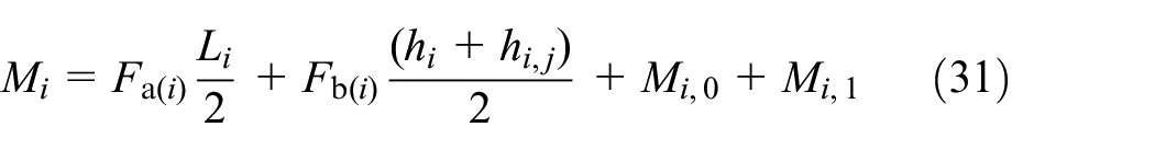
where


where

where
With the rotational stiffness of each individual joint known, the relation between the tilt stiffness of each slipper and their corresponding bottom layer joint is found. The linearized tilt stiffness relative to the neutral configuration of the slipper

where


Representation of a slipper with a hinge joint connecting the slipper and bottom layer joint together and the corresponding parameters.
where

where
Design rules
The sections before presented the general model for the symmetric whiffletree bearing consisting out of the following components: bearing design dimension, kinematics, and kinetostatics. Based on this model, the following rules of thumb can be introduced to aid designers in their design process, given the large degree of design freedom this whiffletree based support offers. Based on the previous models, the following rules should be followed:
Minimize the slipper length given the maximum slipper compression, number of whiffletree layers, and bearing length for the smallest bearing design dimension.
Increase the number of whiffletree layers given an increase in bearing length for smallest bearing design dimension.
Minimize the joint rotational stiffness.
Maximize the joint normal- and shear stiffness.
Maximize the ratio between slipper tilt stiffness and bottom layer joint rotational stiffness.
For validation, the models and design rules will be implemented in a case study.
Design case study
To validate the model and show the potential of this type of support a case study is used. A potential application that currently is not able to make use of the performance characteristics of hydrostatic bearings, is the radial piston pump. Especially the variant where cam rings are implemented, 7 which have counter surfaces with a sinusoidal shape, use roller bearings exclusively because of this constantly varying track. An example of such a pump topology can be seen in Figure 9.

Schematic overview of the radial pump used in the case study where the conventional roller bearing and the newly obtained whiffletree supported hydrostatic bearing are shown.
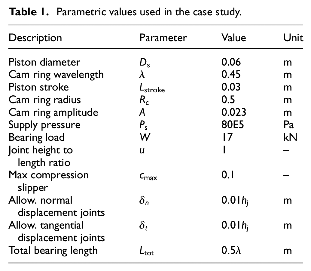
A case study is presented based on the general dimension and performance criteria of an experimental water pump used in the power train of a water hydraulic wind turbine.7,22 The objective of this case study is to show the effect of design choices for the whiffletree support, while simultaneously providing the reader with the required kinematic and kinetostatic criteria that should be strived for when implementing this support in comparable applications. The operating conditions as well as geometrical constraints are defined in Table 1. The main components are the cam ring, piston, and pressure supply source that define this design case. As seen in Figure 9, the bearing is connected to a piston and follows the path described by the cam ring surface. The fluid pressure in the piston is also used as the bearing pressure supply. To simplify this case study, the output pressure is assumed to be equal for the entire stroke cycle. This represents the highest load case. Since this is a case study that solely investigates the kinematics and kinetostatics of the potential support, an example joint is implemented of which the joint to height ratio, the allowable normal displacement, and the tangential displacement are defined. For the slipper solely the maximum compression criteria is defined. These characteristics are dependent on the joint used and primarily depend on its failure criteria, which fall outside the scope of this work. This example will compare a single, double, and triple layer whiffletree support. The visualization of the three embodiments are presented in scale in Figure 10. To obtain the desired piston stroke
Parametric values used in the case study.

To scale dimensionless comparison between the three proposed whiffletree embodiments. The increased number of layers has a positive influence on the total bearing height, given equal bearing length.
The final parameter that effects the dimension of the whiffletree support is the bearing to wavelength ratio. The effect of this parameter is visualized in Figure 11. A sole slipper with rotational hinge is added as reference.

Percentage wise effect of increasing the number of whiffletree layers as function of the bearing length/wavelength has on the total bearing height.
The way this model is set up is such that it can be used by designers to determine the maximum total bearing dimension, required joint rotations, shear and normal stiffness given this set of input parameters.
Model validation
To validate the model, a comparison is made between the analytical model and a Finite Element Model (FEM) using Comsol Multiphysics and the multibody dynamics module. The linkages are modeled as rigid beams, using the rigid domain function and the joints are modeled as hinge joints. The top joint has a prescribed
Results
Following the presented method of determining the bearing topology, the design dimension for all three embodiments of the symmetric whiffletree support can be seen in Table 2. Please note that any rigid connection members do not have a dimension in this work and therefore do not effect the total design dimension.
Minimum rotational stiffness and maximum normal and shear force acting on each individual joint in their corresponding layer.

Based on these dimensions, both kinematic and kinetostatic performance of all three embodiments are presented in Figure 12(a) and (b). Figure 12(a) shows the comparison of the FEM model with the analytical version presented in this work for a triple layer symmetric whiffletree. Only the leftmost joint angle of each layer is shown since the remaining joints in the same layer show equal behavior with the difference of a phase shift. The comparison shows no difference between the analytical and FEM model in terms of kinematic performance, thus validating the presented model. The results of the required joint slipper rotational stiffness with respect to the rotational joint directly connected to the slipper can be seen in Figure 12(b). If the ratio between the rotational stiffness of the slipper and that of the first joint connecting to the slipper is high, this means the angular rotation the slipper makes can be neglected in the total performance of the system.

(a) Joint pivot angles of the FEM and analytical model compared for a triple layer whiffletree. (b) Slipper pivot angle of a triple layer whiffletree with a rotational stiffness ratio of
The validated kinematic model can thus be used to determine the difference between the three different embodiments (Figure 13). Again, only the leftmost joint angle of each layer is shown since the remaining joints in the same layer show equal behavior with the difference of a phase shift.

Joint pivot angles of a single, double, and triple layer whiffletree compared.
The obtained kinematics are used to find the rotational stiffness, maximum normal force, and maximum shear force acting on each individual joint. The resulting determination of stiffness cases for the embodiments can be seen in Table 3.
Minimum rotational stiffness and maximum normal and shear force acting on each individual joint in their corresponding layer.

Discussion
The results concerning the use of the design model and results from the case study will be both discussed.
Case study
A case study has been presented to show how the design model can be implemented, and what kind of performance can be expected by adding a whiffletree as bearing support. The model consists of defining the dimensions, kinematics, and kinetostatics given a certain whiffletree layer set. Given a pre-defined total bearing length of
From the results presented in Figure 13 it can be seen that the whiffletree behaves differently when moving through the concave and convex configurations of the track. Looking at the joint pivot angles shown in Figure 13, it is shown that the addition of whiffletree layers has a negligible small impact on the change in magnitude of the joint pivot angles for the different layers. This means that the top joint in a single layer whiffletree more or less rotates in a similar order of magnitude compared to a whiffletree support with several layers. This can be explained by looking at the angle of the corresponding linkage with the horizontal. The angle of the linkage is approximately equal to the angle of the gradient of the track at equal position. An increase in whiffletree layers does not change this orientation. Thus, no significant change in joint pivot angle is noted due to an increase in whiffletree angles. The top joint thus retains the largest rotational angle and will always be a limiting component in a deformable bearing design. The ratio between the rotational and normal stiffness 17 gives some indication on the severity of the design challenge. These have subsequently been calculated for the different embodiments, seen in Table 4. The results described here show that the increased number of layers in the whiffletree positively influences the top stiffness ratio, which comes at the cost of a higher required performance at the third layer. Depending on the type of joints used, this stiffness requirement may prove to be critical. The required stiffness ratio described in this example would be at the limits of compliant joints as seen in literature, 17 and may require the development of alternatives. On the other hand, the minimum required shear stiffness is lower then the minimum required normal stiffness.
Dimensional normal to rotational stiffness that gives an indication of the required performance for the contact-free joint implementation.

Finally, it is shown that an increase in whiffletree layers results in a decrease in slipper length, and thus a decrease in required compression of each slipper. The slipper pivot angle is shown in Figure 12 for a rotational stiffness ratio between slipper and bottom layer joint for one, two, and three orders of magnitude. It is shown that for a ratio of three orders of magnitude, no noticeable change in slipper pivot angle is noted. Meaning that a rotational stiffness ratio between slipper and bottom layer joint of at least three orders of magnitude is desired.
Model limitations
The design model provides a method to design a 2D whiffletree supported large deforming hydrostatic bearing. There are a few limitations to this design. Firstly, conventional hinge joints are used in the model compared to the preferred compliant joints. This is done for modeling purposes and the friction that occurs in conventional contact joints is neglected in this study. This is done since rigid body mechanics can be used in combination with the conventional hinge joints. Furthermore, it is assumed that the center of rotation stays at the same place while using compliant joints in the system. Since the scope of this project is to find a general solution regarding the kinematics and kinetostatics, and this simplification is valid. Secondly, the total perimeter of the bearing increases when multiple smaller slippers are connected together compared to a single slipper of equal length and width. The increase in bearing perimeter results in an increase in fluid losses of the bearing. The perimeter of the bearing, and thus the fluid losses, can be reduced by connecting all slippers together thereby creating a single slipper that consists of multiple segments connected by elastic joints. This will also change the pressure profile from the single slippers as shown in Figure 10 to a continues pressure profile which can be described by a higher order polynomial. It is recommended to look into the behavior of this single continuous slipper in future research. Thirdly, the total joint length is restricted by the total linkage length. This is shown in the assumption that the bottom layer joint has a length of half the slipper length and each ascending joint is twice the length of the joint one layer below, resulting in the maximum allowable bearing length on each linkage. Fourthly, this work gives an explanation for the static and quasi-static state of a whiffletree supported hydrostatic bearing. Further research can be conducted to find the possible changes in results when perturbations and stability parameters in the dynamic state are taken into account. Finally, the slippers are geometrically not limiting the model and thus placed directly next to each other. In reality, when the bearing moves into a concave configuration, the slippers need to pass through each other which results in jamming. This can be solved by either using less of the maximum bearing design space or adding a gap between the slippers large enough such that the slipper can pass without contact. The latter option needs to follow from an extension of the model, to determine this exact gap dimension without influencing the bearing dimensions to much.
Conclusions
This work shows the potential of a whiffletree support system to increase the capability of 2D compliant hydrostatic bearings to follow non-constant curvature counter surfaces. An approximately quadratic relation is found between the slipper compression and length, and thus the required slipper compression is reduced for a decrease in slipper length. It is shown that an increase in whiffletree layers does not greatly affect the joint pivot angles of the ascending layers. However, the addition of extra layers in the whiffletree does lower each individual slipper length, reducing the required compression of the slipper. A ratio of at least three orders of magnitude between the slipper tilt stiffness and bottom layer joint is required to show no noticeable influence caused by the tilting of the slipper. Finally, the whiffletree can be used to rotate smaller slippers reducing their required compression while maintaining load capacity.
Footnotes
Handling Editor: Chenhui Liang
Declaration of conflicting interests
The author(s) declared no potential conflicts of interest with respect to the research, authorship, and/or publication of this article.
Funding
The author(s) received no financial support for the research, authorship, and/or publication of this article.