
Abstract
Based on Hertz contact theory, two parabolic cylinder normal contact models are established. The effect of contact angle on normal approach, actual contact area, and normal contact stiffness are investigated, and the effect of the distance from the focus to the directrix (focus distance) on the mechanical characteristics of the models is further analyzed. The parabolic cylinder contact model was verified by simulation analysis and comparison with cylinder contact model. The results demonstrated that the contact angle, focal distance, and load have significant effects on the mechanical properties of the model. The simulation data are basically consistent with the contact model data, and the parabolic cylinder contact model and cylinder contact model have the same change trend. The results verify the correctness of the parabolic cylinder contact model and reveal the variation of the mechanical properties of the contact model.
Introduction
Since the Hertz contact theory was introduced, 1 many scholars have performed detailed research on the contact problem of two micro-convex bodies. In general, the study of this problem considers mainly the macroscopic properties of the asperity elastic modulus and geometric parameters, while microscopic properties, such as the surface morphology and surface roughness of the asperity, are less taken into consideration. 2
In recent years, scholars have conducted a lot of research on the surface morphology of asperities. The most typical contact model is the cylinder contact model. Based on the Hertz theory, Johnson 3 and Radzimovshy 4 proposed two cylindrical elastic contact models and carried out detailed research on the internal and external contact of their models. Li et al. 5 proposed an elastic-plastic contact model between rigid sphere and elastic-plastic plane by modifying Johnson’s contact model, which was verified by finite element analysis. Goldsmith 6 also proposed a cylindrical contact model, which is suitable for internal contact collisions between cylinders. Pereira et al. 7 conducted a comparative study on the above three models, and indicated that these cylindrical models are associated with three main disadvantages, including low computational efficiency of the program, they consider only elastic contact, and they include logarithmic function, which may affect the scope of model application. Cinar and Sinclair 8 investigated the elastic-plastic contact of an infinitely long cylinder under frictionless and fully-bonded contact conditions, and improved the computational efficiency of the model using proper mesh expansion techniques. Sharma and Jackson 9 employed the FEM to research the elastic-plastic contact between a cylinder and a rigid plane under plane stress, and analyzed the convergence of the FE mesh. Guo et al.10,11 proposed the elastic-plastic contact model of cylinder and cosine wave under different contact angles. More specifically, they investigated the effect of normal contact deformation, normal contact stiffness, and actual contact area on the mechanical characteristics of the contact model under different axis contact angles. Huang et al. 12 developed a fractal contact model of two cylinders based on the Hertz theory and the MB fractal theory.13–15 Their model analyzed the effect of fractal dimensions, cylinder radius, and contact mode on load and contact area. Li et al. 16 studied the normal contact stiffness of the joint surfaces of two cylinders by modifying the MB fractal model. They developed a simulation model to analyze the effect of contact area, load, and friction factor on contact stiffness.
In addition, there are relevant important studies on spherical and ellipsoidal contact models. The research on spherical elastic contact was first conducted by Hertz, 17 who obtained a closed-form solution for the spherical elastic contact problem. Bondareva 18 obtained an orthogonal analytical solution of the elastic sphere displacement problem by studying the general solution of the elastic sphere contact problem. Zhupanska 19 investigated the normal contact problem of an elastic sphere, and analyzed the contact stress and surface displacement of the sphere. Argatov 20 studied the symmetry and nonlinear contact problems of an elastic sphere, and obtained an approximate solution of the elastic sphere contact under a small contact area condition. Yuan et al. 21 explored the friction properties of spherical contact surfaces, and suggested that high-frequency and large-fluctuation loads are the key factors affecting spherical contact sliding. Halling and Nuri 22 proposed a solution to the deformation of spherical or ellipsoidal convex bodies under the effect of work hardening, assuming independent deformation between asperities. Ghaednia et al. 23 studied the contact problem between an elastic-plastic sphere and an elastic-plastic plane through a large number of finite element analysis examples, which gave the solution formulas of relevant contact parameters. Considering the inapplicability of Hertz elastic contact theory to elastic-plastic deformation materials, Rodriguez et al. 24 studied the effect of reducing modulus on indenter deformation by finite element method. Kogut and Etsion 25 proposed an elastic-plastic contact finite element model of deformable sphere and rigid plane, which analyzed the mechanical characteristics of contact load, actual contact area and average contact pressure in elastic stage, elastic-plastic stage, and complete plastic stage. In order to use particle method to simulate granular materials, Olsson and Larsson 26 proposed a method to calculate the contact load and contact area of two different elastic-plastic spheres. The results of finite element analysis are in good agreement with the results of the model. Ghaednia et al. 27 reviewed the research progress of single asperity contact model in recent years. Through comparative analysis of cylinder, sphere, sinusoidal, and wavy contact models, it was found that the average contact pressure of contact model in the elastic-plastic stage changes with the change of boundary conditions and geometry, which is not affected by the ratio of hardness and yield strength.
It is well known that parabolic cylinder contact models are also typical contact models. Steuermann 28 proposed an even-order parabolic cylinder elastic contact model, which considered the parabolic cylinder model as an elastic half-space. However, Steuermann studied only the elastic deformation stage of the parabolic cylinder model.
In machining processes, and especially in precision machining, the machining surface often has regular and periodic features. 29 For instance, in the grinding process, regular waves are formed on the machined surface. 30 Corresponding surface equations can be developed based on the shape of these ripples. These surface ripples can be mainly divided into cylindrical, elliptical, and parabolic waves. By studying the regular elastic-plastic contact model, the mechanical properties of regular joint surfaces can be further analyzed, providing theoretical guidance for the contact stiffness between regular joints. Thus, the development of an elastic-plastic contact model of two regular bodies is the basis for studying the mechanical properties of regular joint surfaces.
In the above-mentioned studies, the research on elastic-plastic contact models of cylinders, spheres, and ellipsoids has been very mature, while, the research on parabolic cylinder contact models has been stagnant. Although Steuermann studied the elastic parabolic contact model, it did not analyze the mechanical properties of the contact model in the elastic-plastic stage and the fully plastic stage, and did not consider the influence of the contact angle. Therefore, in this paper, a parabolic cylinder elastic-plastic contact model with different contact angles is proposed to explore the change rules of normal approach, normal contact stiffness, and actual contact area. The research results are compared with the cylindrical contact model, as well as FEM analysis results.
Parabolic cylinder model development
Elastic stage
If the focus distance of two parabolic cylinders is p, the equation of the parabolic cylinder surface in parallel contact with two axes can be expressed as:

where z1 and z2 are the vertical distances from a point on the upper and lower contact surfaces to the origin, respectively.
The parabolic cylinder surface

If the initial distance between two corresponding points on the z-axis of the two parabolic cylinder surfaces is h, then, the initial gap between any two points on the two parabolic cylinder surfaces is:

By rotating the coordinate axis, equation (3) can be simplified as:

Figure 1 illustrates a schematic of the contact model of two parabolic cylinder surfaces. As it can be seen in Figure 1(a), the initial contact state is point contact. If a load is applied along the z-axis to the parabolic cylinder model surface, the two parabolic cylinder surfaces around the contact point will deform and the contact state will change from point contact to surface contact (Figure 1(b)).

Parabolic cylinder model schematic: (a) before force application and (b) after force application.
Assuming that the normal approach of the parabolic cylinder contact surface at

Considering the initial gap between any two points on the parabolic cylinder surface, the distance L between any two points on the contact surface can be expressed as:

In the elastic deformation stage of the parabolic cylinder model, the general equation of the deformation of points in the semi-infinite boundary plane under distributed pressure is as follows 31
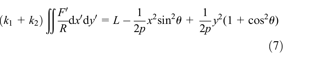
where
Calculating the integral of equation (7),
32
under the action of the contact load

where
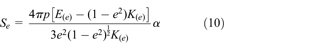
The radius of the contact ellipse curvature can be obtained by:

At the same time, the contact state of the parabolic cylinder contact model will eventually become surface contact, and the final actual contact area
In addition, the relationship between the average contact pressure
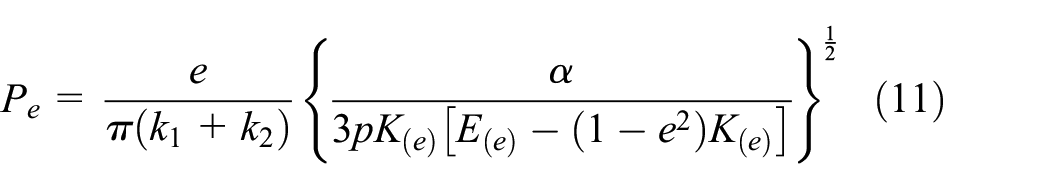
The relationship between the normal contact stiffness

With the increase of the normal approach, the parabolic cylinder model will begin to enter into the plastic stage. The von Mises yield condition indicates that when the elastic deformation ratio reaches a certain value, the material begins to yield. The yield condition of material can be expressed as:

According to equations (10) and (11), the actual contact area

The normal approach

The normal contact stiffness

Plastic stage
When the parabolic cylinder contact model is in the fully plastic stage, the average contact pressure can be considered as equal to 2.8 times the yield strength 33

Abbott 34 performed accurate measurements and comparisons of the contact surfaces, and reported that, in the plastic stage, the actual contact area is equal to twice the actual contact area in the elastic phase. According to equation (10), the relationship between the actual contact area of the model in the plastic stage and the normal approach is as follows:

The total force

Subsequently, the normal contact stiffness

Tabor
35
shows that the load increases by about 300 times from the beginning of yield to the full plastic deformation. When the contact model has just reached the full plastic stage, the normal approach

Elastic-plastic stage
With the increase of the normal approach, the parabolic cylinder contact model will enter into the fully elastic stage, elastic-plastic stage, and fully plastic stage in turn. When the normal approach reaches the initial yield point
Zhao et al. 36 proposed the use of a cubic spline interpolation function to describe the elastic-plastic deformation of asperities. This function determines the relationship of the actual contact area and the average contact pressure with the normal approach. The present study intends to use the cubic spline interpolation function and discuss the applicability of this method to parabolic cylinder contact models.
The cubic spline interpolation function is as follows:

To ensure the continuity and smoothness of the deformation process, the actual contact area and average contact pressure should satisfy the following relationships at the critical point 37 :

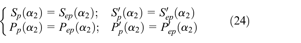
where
Based on the above conditions, a relational expression including the cubic spline interpolation function can be established:

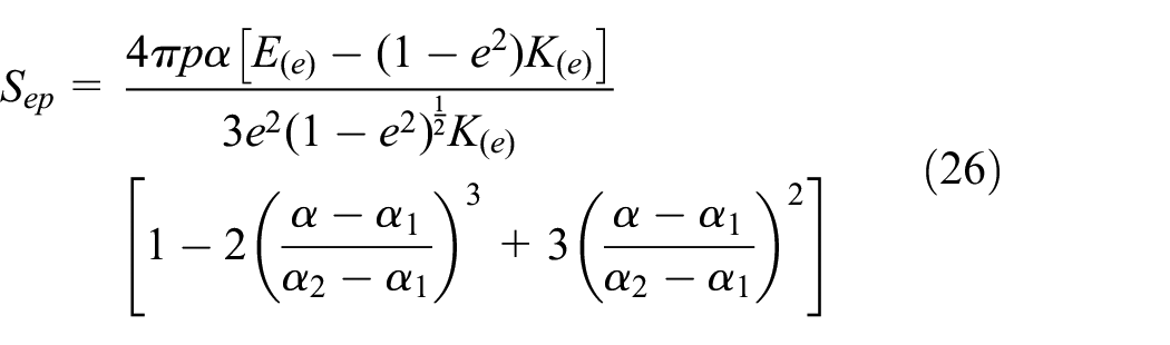
By substituting the relationship between actual and average contact area with the normal approach in the elastic and plastic stages of the parabolic cylinder contact model into equation (25), the following equation can be obtained:

Figures 2 and 3 display the relationship between actual and average contact pressure obtained by the cubic spline interpolation function with the normal approach. The selected material parameters were as follows: p = 5 mm,

Variation of actual contact area with normal approach.
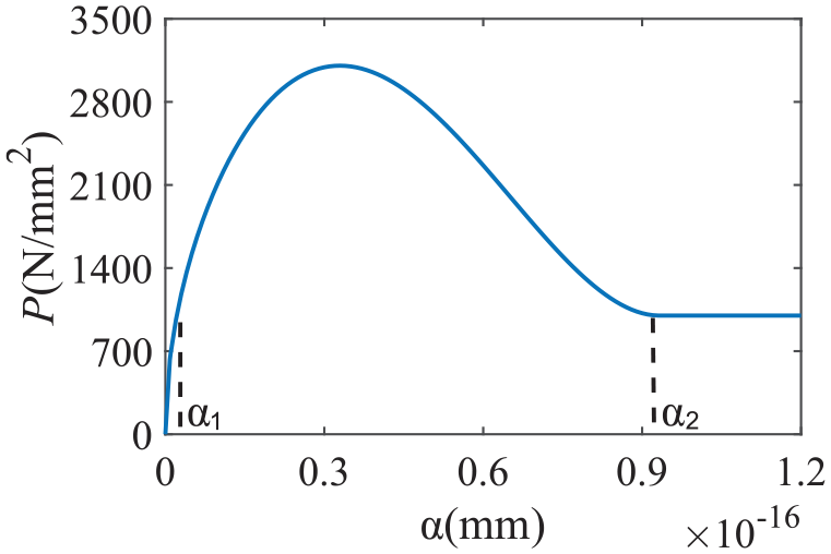
Variation of average contact pressure with normal approach (cubic spline interpolation function).
The curve of the average contact pressure of the parabolic cylinder contact model in the elastic-plastic deformation stage obtained by the cubic spline interpolation function can ensure only continuity and smoothness, but not monotonicity, which results in oscillations. Therefore, in order to tackle the above problems, this study intends to use an elliptic curve of lower order to further model the changes in the elastic-plastic average contact pressure with normal approach.
The coordinate of the parabolic cylinder contact model at the initial yield point is
Based on the above constraints, the elliptic curve equation can be expressed as follows:
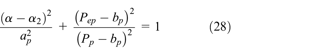
where
The average contact pressure and slope of the contact model at the initial yield point can be respectively obtained by:


According to the continuity and smoothness requirements, the following results can be obtained:

The result of equation (31) can be obtained as follows:

Finally, the relationship between the average contact pressure

where
Figure 4 demonstrates the relationship between the average contact pressure obtained using the elliptic curve and the normal approach. The parameters of the parabolic cylinder model were consistent with those presented in Figure 2. It can be seen in Figure 4 that the average contact pressure versus normal approach curve satisfies the conditions of smoothness, continuity, and monotonicity. Therefore, the elliptic curve is suitable for calculating the average contact pressure.
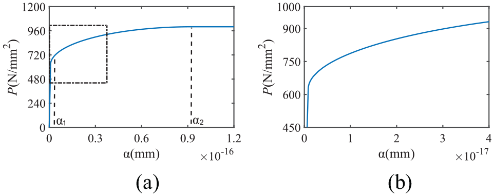
Average contact pressure variation with normal approach (elliptic curve): (a) overall change and (b) local amplification (indicated by the rectangular box in (a)).
Considering that the normal contact stiffness of the parabolic cylinder contact model has the same change trend with the normal approach, the elliptic curve was used to model the relationship between normal contact stiffness and normal approach in the elastic-plastic deformation stage.
By following again the above-described solution equations (28)–(33), the relationship between the normal contact stiffness

Figure 5 shows the relationship between normal contact stiffness and normal approach obtained using the elliptic curve approach. The parameters of the parabolic cylinder model were consistent with those in Figure 2. As it can be seen in Figure 5, the curve of normal contact stiffness with normal approach meets the smoothness, continuity, and monotonicity conditions, indicating that the elliptic curve is applicable also to normal contact stiffness.
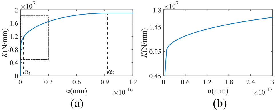
Variation of normal contact stiffness with normal approach: (a) overall change and (b) local magnification (indicated by the rectangular box in (a)).
Analysis and comparison
The Matlab and ABAQUS software were used for simulation analysis and comparison to verify the correctness of the proposed parabolic cylinder contact model.
Comparative analysis between the parabolic cylinder and cylindrical models
Figures 6 and 7 compare respectively the normal approach and normal contact stiffness between the parabolic cylinder and cylindrical models.
10
The selected material parameters were as follows: p = 0.25 mm, R = 0.5 mm,

Comparison of the normal approach between the parabolic cylinder and cylindrical models.
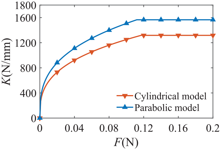
Comparison of the normal contact stiffness between the parabolic cylinder and cylindrical models.
Finite element simulation analysis
In this paper, the ABAQUS software was used to analyze the elastic-plastic contact of the parabolic cylinder model. The selected material parameters were as follows:

Meshed parabolic cylinder model: (a) 45°, (b) 60°, and (c) 90°.
The deformation contours along the Y-direction of the parabolic cylinder model obtained by the post-processing module are shown in Figure 9, where the model is at a contact angle of 45° and the load is 0.1 N. It can be observed in Figure 9(b) that the deformation of the contact surface was symmetrically distributed, and the maximum deformation occurred at the central position. During the contact process, the contact surface formed a face-to-face contact which originated from the initial point-to-point contact.

Contours of deformation distribution: (a) overall deformation and (b) local deformation.
Figure 10 compares the simulation and theoretical values of the normal approach under different contact angles. As it can be observed, there was a certain error between the simulation values and the theoretical values of the normal approach; however, their change trend was consistent. The normal approach increased with increasing load, and exhibited an exponential relationship in the elastic stage and a linear relationship in the plastic stage.

Comparison between the simulation and theoretical values of the normal approach at contact angles of: (a) 45°, (b) 60°, and (c) 90°.
To further analyze the error between the simulation and theoretical values of the normal approach, the simulation and theoretical values of the normal approach under a load of 0.05 and 0.15 N were compared (Table 1). The maximum normal approach error was 7.61% and the minimum was only 4.83%. Furthermore, it can be seen that, under the same load, the normal approach increased with increasing contact angle.
Comparison between simulation and theoretical values of the normal approach.

Effect of normal approach on normal contact stiffness
Figure 11 shows the effect of normal approach on normal contact stiffness. The selected material parameters were as follows: p = 0.25 mm,

Effect of normal approach on normal contact stiffness.
Effect of normal approach on actual contact area
Figure 12 shows the effect of normal approach on actual contact area. The selected material parameters were as follows: p = 0.25 mm,
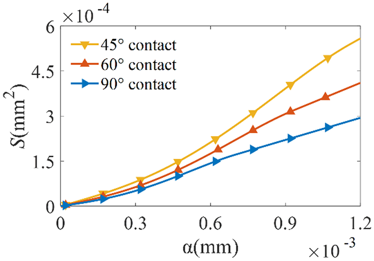
Effect of normal approach on actual contact area.
Effect of focus distance
Figures 13 to 15 show the effect of focus distance on normal approach, normal contact stiffness, and actual contact area, respectively. The selected material parameters were as follows: p = 0.25 mm,

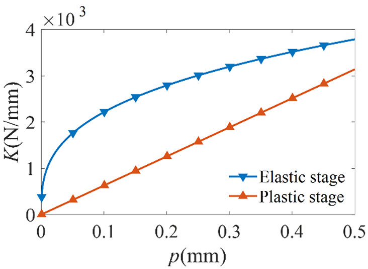
Effect of focus distance on normal approach.
Effect of focus distance on normal contact stiffness.

Effect of focus distance on actual contact area.
Conclusions
In this paper, based on the Hertz contact theory, an elastic-plastic contact model of parabolic cylinder convex bodies with different contact angles was developed, and the change rules of the normal approach, normal contact stiffness, and actual contact area in the parabolic cylinder contact model were investigated. In the elastic-plastic contact stage, the relationship between actual contact area and normal approach was established through the cubic spline interpolation function, while the relationship of the average contact pressure and normal contact stiffness with the normal approach was established through the elliptic curve. The establishment of the elastic-plastic contact model of two parabolic cylinders provides the theoretical basis for further research on the contact stiffness of regular parabolic cylinders. The following conclusions can be drawn:
The simulation value of the normal approach of the contact model is compared with the theoretical value, the maximum normal approach error was 7.61% and the minimum was only 4.83%.
The actual contact area increased with increasing normal approach. In the elastic and elastic-plastic stages, the normal contact stiffness increased with increasing normal approach; in the plastic stage, the normal contact stiffness was independent of the normal approach.
The normal approach increased with increasing contact angle. The normal contact stiffness and actual contact area decreased with increasing contact angle.
The normal approach increased with increasing focus distance, and the normal contact stiffness decreased with increasing focus distance. In the elastic and elastic-plastic stages, the actual contact area increased with increasing focus distance; in the plastic stage, the actual contact area was not affected by the focus distance.
Footnotes
Appendix
Handling Editor: Chenhui Liang
Declaration of conflicting interests
The author(s) declared no potential conflicts of interest with respect to the research, authorship, and/or publication of this article.
Funding
The author(s) disclosed receipt of the following financial support for the research, authorship, and/or publication of this article: NSFC (Grant No. 51875009).