
Abstract
A mesh flexible spoke non-pneumatic tire is designed to avoid tire burst and other hidden dangers in the traditional pneumatic tires, and improve driving safety. The purpose of this study is to explore the fatigue performance and fatigue life prediction method of the non-pneumatic tire and analyze the influence of structural parameters on the fatigue life of non-pneumatic tire. Based on the crack propagation method of energy release rate by J-integral, the fatigue life of the meshed flexible spoke non-pneumatic tire is predicted. Using numerical simulation method, the influence of key structural parameters, such as the curvature, unit angle and thickness of the lateral spoke and the tread thickness, on tire fatigue life is studied. The results show that the fatigue life prediction method proposed can be used to predict the fatigue life of flexible spoke non-pneumatic tire, and the fatigue life of non-pneumatic tire with flexible spoke can be improved by selecting appropriate structural parameters, which could provide some reference for the structural optimization design of the fatigue performance of the non-pneumatic tire.
Introduction
Since the advent of the non-pneumatic tire, with its performance advantages, it has become a hot research topic for many scholars and related enterprises at home and abroad. As a kind of safety tire, it can not only meet the basic performance requirements such as load-bearing and shock absorption, but also can avoid the risk of tire burst from the root, reduce the accident rate, and significantly improve the driving safety. 1
In view of the basic mechanical properties of the non-pneumatic tires, relevant researchers have carried out a lot of research work. In the aspect of vertical mechanical properties research, Gasmi et al. 2 simplified the tread of a non-pneumatic tire as Timoshenko curved beam and the flexible spoke as linear spring, and established a quasi-static two-dimensional analytical model of the non-pneumatic tire. Kucewicz et al. 3 carried out a vertical static deflection simulation test on Tweel and honeycomb tire, and analyzed the influence of hub vertical displacement, tread deformation, and grounding pressure on the geometry of the flexible spoke structure. In terms of longitudinal mechanical properties research, Mazur 4 obtained the rolling resistance of non-pneumatic tire based on the prototype test method and drew the curve of rolling resistance changing with speed. Jackowski et al. 5 found that the non-pneumatic tire has a high hysteresis coefficient value, which is 1.5–2 times of the pneumatic tire. With the increase of the load, the rolling resistance of the non-pneumatic tire is close to or even significantly higher than that of the pneumatic tire. At the same time, Ju et al. 6 found that the multicellular geometry and PU materials can reduce the elastic hysteresis loss of non-pneumatic tires, thus effectively reducing the rolling resistance of tires. In the research of lateral mechanical properties, Pewekar and Gaikwad 7 studied the deformation mechanism of a non-pneumatic tire under compression, lateral shear, lateral torsion and circumferential torsion, and verified the strength of the tire under different load conditions. In the study of grounding characteristics, Zang et al. 8 compared and analyzed the ground pressure distribution rules of pneumatic safety tire and mechanical elastic wheel under different loads through static grounding characteristic test. Du et al. 9 compared and analyzed the grounding characteristics of non-pneumatic tires with different camber angles under the conditions of free-rolling, braking, and driving. The results show that with the increase of camber angle, the tread will gradually show local wear. In the research of vibration characteristics, the vibration mechanism and influencing factors of non-pneumatic tire are emphatically explored. Narasimhan et al. 10 found that in the process of non-pneumatic tire entering and leaving the grounding area, the flexible spoke generates self-excited vibration, which causes the overall tire vibration and noise. The thickness of flexible spoke has a certain impact on its vibration amplitude, but has no effect on the vibration frequency. Ning et al. 11 proposed a new type of non-pneumatic tire with damping spring, studied the influence of spring stiffness in tire on natural frequency, and verified the correctness of stiffness theory of non-pneumatic tire through numerical simulation and prototype test method. In addition, the structural parameters (geometric parameters and material parameters, etc.) have great influence on the vertical stiffness, rolling resistance, and ground pressure distribution of the non-pneumatic tire. 12 Based on static structure analysis and modal analysis, Shashavali et al. 13 compared and analyzed the influence of nylon 4-6 and nitrile butadiene rubber on the mechanical properties of non-pneumatic tires. Rugsaj and Suvanjumrat 14 used a validated NPT model to find the right spoke thickness to achieve the same radial stiffness as a pneumatic tire.
The above research is mainly about the basic mechanical properties of the non-pneumatic tires, but the durability of tires is also the focus of attention. Based on the principle of honeycomb mechanics.15,16 Ju et al. 17 designed flexible honeycomb structures with positive and negative cell angles, and compared and analyzed the local stress of honeycomb structures with different cell angles under uniaxial loading. The results show that honeycomb structure with large positive cell angle can make honeycomb tire have lower local stress and better fatigue resistance. Sriwijaya and Hamzah 18 studied the influence of pavement inclination angle on the stress distribution of the flexible spoke structure of non-pneumatic tire. The research shows that the larger pavement inclination angle will increase the equivalent stress distribution value of the honeycomb flexible spoke structure, thus accelerating the failure of the flexible spoke structure. Wang et al. 19 found that the concentration of stress, strain, and strain energy density of C-type non-pneumatic tire is consistent with that of the support structure of the non-pneumatic tire. Zhang et al. 20 analyzed the static grounding performance of the staggered structure non-pneumatic tire, and used FE-SAFE to predict the tire fatigue life. Qi et al. 21 found that the relatively appropriate honeycomb support density can overall stress level of the tire is low, which can effectively avoid damage due to stress concentration. Xiao et al.22,23 proposed a method to predict the fatigue life of mechanical elastic tire by using finite element life design, and verified the theoretical calculation and simulation results through experiments. At the same time, a new virtual test site model based on finite element analysis is proposed. Combined with the random vibration damage analysis method, the life of non-pneumatic tire is accurately predicted. At the same time, as an important index of fatigue analysis and structural optimization, strain energy density is widely used in tire fatigue life analysis. Through finite element simulation and tire durability test, Liang et al. 24 discussed the effectiveness of strain energy density gradient in tire fatigue failure and fatigue life prediction, studied the sensitivity of strain energy density gradient to tire structural parameters by using sensitivity analysis technology, and established the relationship between structural parameters and fatigue life. Wang et al. 25 uses the steady-state rolling analysis of finite element method and the fatigue life equation of rubber (carcass) in the bead area to predict the bead fatigue life (N) and bead failure driving distance (D) based on the maximum strain energy density range method.
While the basic mechanical properties of the non-pneumatic tires are studied in detail, the fatigue failure problem is preliminarily explored. However, the research on fatigue life prediction method and fatigue failure evaluation index of non-pneumatic tire is relatively less. Therefore, based on the crack propagation method of J-integral to solve the energy release rate, this paper carries out the fatigue life prediction of a mesh flexible spoke non-pneumatic tire, and explores the influence of the key structural parameters of mesh flexible spoke non-pneumatic tire on the fatigue life, so as to provide some guidance for solving the fatigue failure problem of the non-pneumatic tires.
Structural analysis of mesh flexible spoke non-pneumatic tire
Based on the size of 195/50R16 radial tire and referring to spider web structure, a kind of mesh flexible spoke non-pneumatic tire is proposed in this work, as shown in Figure 1. The whole tire is mainly composed of tread, flexible spoke, and hub. The flexible spoke can be divided into two components: the circumferential spoke and the lateral spoke.

The structure of the mesh flexible spoke non-pneumatic tire.
Theoretical analysis of fatigue life prediction
The main failure mode of non-pneumatic tire is fatigue failure caused by alternating stress. In the rolling process of non-pneumatic tire, the flexible spokes will bear large extrusion tensile alternating stress and single alternating stress for a long time, resulting in fatigue failure of flexible spokes. At the same time, fatigue failure is a process of crack propagation, and fracture mechanics is the theoretical basis of crack propagation life. Given the initial geometry of crack and the time history of crack energy, the fatigue crack propagation rate, and load cycle times of material can be predicted according to the known crack propagation characteristics of material. The crack propagation can be expressed as the process that the crack continues to generate new cracks along a certain direction. Based on the theory of fracture mechanics, the crack propagation process can be divided into crack formation period, micro crack period, macro crack propagation period, and crack fracture. It can also be integrated into two stages of crack nucleation and crack propagation. The corresponding fatigue life is called crack generation life and crack propagation life.
Rubber fracture theory
In fracture mechanics, the stress intensity factor method and the energy method can be used to describe the crack propagation. The stress intensity factor describes the brittle failure of linear elastic materials, which can-not be applied to rubber materials. The energy rule describes crack growth as the generation of new cracks, which needs to release the energy stored in the material itself. This method can better describe the fatigue failure of nonlinear materials. Therefore, the energy method is used to predict the fatigue life of the mesh flexible spoke non-pneumatic tire.
The energy consumed per unit area of crack propagation is an important parameter to characterize the fatigue failure of rubber materials. The expression is as follows:

Where T is the energy release rate, U is the total elastic strain energy of the material, A is the area of new cracks generated by crack propagation, and the negative sign is the generation of new cracks.
The specific expression of the energy release rate at the crack tip is as follows:

Where K is the material intrinsic constant, WC is the strain energy density at the crack tip, and a is the crack size. It can be seen from equation (2) that there is a functional relationship between the energy release rate and the strain energy density and the crack size, so the strain energy density can replace the energy release rate to characterize the fatigue life of rubber materials.
In the process of crack growth, the energy release rate represents the strength of crack growth, while the crack growth rate is the size of crack propagation under unit cycle number, which is the key physical quantity in the process of crack growth, and its expression is:

Where r is the crack growth rate, a is the crack size, and N is the number of cycles.
Based on Thomas crack growth model, 26 the fatigue life of rubber materials is predicted. The model is as follows:

Where Tc is the critical energy release rate for material fracture, Tmax is the maximum energy release rate in the loading cycle, rc is the critical crack growth rate of the material, F is the power exponent.
By changing the mathematical integral of the crack growth model, the equation of fatigue cycle number can be obtained as follows:
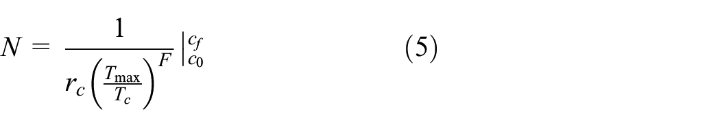
Where: cf is the critical crack size, c0 is the initial crack size.
The energy release rate and J-integral are equivalent in computational mechanics, that is, T = J. Therefore, the J-integral of a crack tip can be obtained by numerical calculation, and then the fatigue life of rubber material can be obtained by equation (5).
J-integral theory
J-integral solves the influence of plastic deformation at crack tip on energy release rate of elastic-plastic materials. It can characterize the stress-strain field strength at the crack tip, and is an important parameter in the fatigue life analysis of elastic-plastic materials.
J-integral describes the integral value of a loop around the crack tip, and its path is shown in Figure 2. Γ is an arbitrary loop around the crack tip, and its J-integral calculation equation is as follows:

Where

J-integral circuit and equivalent integral region.
Based on equation (6) to solve the J-integral, it is difficult to solve the stress and strain in the integral loop, although the integration path will not affect the results. Therefore, the method of equivalent region is used to solve the J-integral, and the equivalent region A is shown in Figure 2. When solving J-integral based on ABAQUS, the grid elements around the crack tip can be used to form the equivalent area, in which the equivalent area formed by the first circle of grid elements outside the crack tip is called the crack tip, the equivalent area formed by the second cycle of grid element is the first contour integral, and so on. The contour integral diagram is shown in Figure 3.

Contour integral diagram.
Tire fatigue life prediction
Based on ABAQUS, the J-integral of tire preset crack model was calculated. Due to the large difference between the crack size and the thickness of the lateral spoke, in order to analyze the fatigue life of the mesh flexible spoke non-pneumatic tire lateral spoke more accurately, in this work, the J-integral of crack tip is calculated based on the global-local model, that is, the key local position is selected for analysis based on the global model. The flow chart of fatigue life prediction is shown in Figure 4.

Flow chart of fatigue life prediction.
Construction of crack model
Determine the location of the crack
According to the equation (2), the energy release rate has a linear relationship with the strain energy density. Therefore, the maximum strain energy density is selected as the fatigue failure location of the mesh flexible spoke non-pneumatic tire. In the finite element model of mesh flexible spoke non-pneumatic tire, there are two butt contact surfaces: one is the contact surface between ground and tread; The second is the contact surface between flexible spoke and tread. The contact type between the tread and the ground is tread contact. The normal behavior defaults to hard contact. The penalty function is selected to define the tangential behavior, and the friction coefficient is set to 0.7. The contact surface between the flexible spoke and the tread is set as binding contact. During the analysis, the ground is completely fixed and the tire retains only the radial displacement component. By querying relevant data, the rated load of 195/50R16 tire is 5000 N. Therefore, in the analysis of bearing characteristics, 5000 N vertical load is applied to the mesh flexible spoke non-pneumatic tire.
Through the analysis of the load-bearing characteristics of the mesh flexible spoke non-pneumatic tire, it can be concluded that, the maximum strain energy density is located at the maximum bending point of the middle cavity lateral spoke. Therefore, this work proposes that the maximum bending position of the middle cavity lateral spoke is the fatigue failure position. The crack location is shown in Figure 5.

Schematic diagram of crack location.
Determine to crack size
Because of the complexity of the tire in the actual driving process, 0.2 mm is selected as the initial crack size c0 and 0.2 mm is selected as the conservative estimation of fatigue life. The thickness of lateral spoke is 4 mm, and the critical crack size cf is defined as 2 mm.
Determine crack type
The growth direction of the edge crack and the center crack is along the length direction, and the surface crack can propagate in the surface and depth directions. Based on the location and characteristics of the cracks in the structure, the fatigue life of the lateral spoke of the meshed flexible spoke non-pneumatic tire was predicted based on the edge crack.
J-integral calculation
In order to avoid the instability of integral value in the analysis process, the contour is added to improve the precision of the J-integral. Ignoring the first and second contour integral values, the average value of the third contour integral value is taken as the J-integral of the crack tip, that is, the energy release rate at the crack tip. The J-integral value corresponding to 0.2 mm initial crack is 0.3546 N/mm.
Fatigue life prediction of tire
The relevant data of rubber materials used for the flexible spoke of the mesh flexible spoke non-pneumatic tire are shown in Table 1.
Rubber material parameters. 27

The results of J-integral calculation and material parameters of support body are brought into the fatigue life calculation equation (5):

Through calculation, the actual rolling of the tire is 12,665,127 cycles.
The diameter of the mesh flexible non-pneumatic tire is 602 mm. According to the equation of circumference, the distance of tire rolling in one cycle is 1.89 m. Therefore, the actual driving distance of the meshed flexible spoke non-pneumatic tire rolling 12,665,127 cycles is about 23,900 km.
Analysis of influencing factors on tire fatigue life
Combined with equations (2) and (5), the relationship between the number of fatigue cycles and strain energy density can be deduced as follows:

Where K is the intrinsic constant of the material, a is the crack size, rc is the critical crack growth rate of the material, F is the power exponent, Wc is the strain energy density, Tc is the critical energy release rate of material fracture. It can be seen from the above relationship that the number of fatigue cycle is inversely proportional to the strain energy density under certain parameters. The higher the strain energy density is, the less the fatigue cycles are. Therefore, the strain energy density was used to characterize the fatigue life of the mesh flexible spoke non-pneumatic tire in this work. The influence of structural parameters on the variable energy density was analyzed, and the specific influence of structural parameters on the fatigue life of the tire was analyzed by the change law of the strain energy density. The structural parameters used are shown in Figure 6. Where k is the curvature of the lateral spoke, a is the unit angle of the lateral spoke, l is the lateral spoke thickness, and d is the tread thickness.

Tire structure parameters.
Influence of the lateral spoke curvature on fatigue life
In order to improve the cushioning performance of the mesh flexible spoke non-pneumatic tire, the bending radian of the lateral spoke in each layer of cavity is added in the design of the lateral spoke, and the curvature (k) is used to characterize the bending degree of the lateral spoke. The greater the curvature is, the greater the bending degree of the lateral spoke is. The design scheme of lateral spoke curvature is k = 0, k = 1/72, k = 1/37, k = 1/25. The influence of different lateral spoke curvature on the fatigue performance of mesh flexible spoke non-pneumatic tire is analyzed. The analysis results are shown in Figures 7 and 8.

Distribution of strain energy density under different curvature of lateral spoke.

Variation curve of strain energy density of tire with different lateral spoke curvature at the same deformation position.
Figure 7 shows the distribution of strain energy density of tire models with different lateral spoke curvature under 5000 N radial load. The strain energy density still exists the concentration phenomenon after changing the curvature of the lateral spoke. The maximum value is located at the maximum bending point of the middle cavity lateral spoke, which is the position where the tire is most prone to fatigue failure. At this time, the axial distribution of the strain energy density in the region is high in the middle and low at the two ends.
According to the change curve of strain energy density in Figure 8, the difference of strain energy between curvature 0 and curvature 1/25 is the largest. With the increase of the curvature of lateral spoke, the strain energy density increases, and the fatigue life of tire decreases gradually.
Influence of the lateral spoke unit angle on fatigue life
Based on the change of the unit angle of the mesh flexible spoke non-pneumatic tire, the change rule of its fatigue performance was analyzed. The change schemes of the unit angle of the lateral spoke are 15°, 12°, 10°, and 8.5° respectively. The analysis results are shown in Figures 9 and 10.

Distribution of strain energy density under different unit angle of lateral spoke.
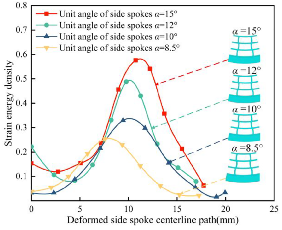
Strain energy density curve of tire with different unit angles of lateral spoke at the same deformation position.
Figure 9 shows the distribution of strain energy density of tire model with different unit angles of lateral spoke under 5000 N radial load. It can be seen from the figure that the main concentrated distribution position of strain energy density remains unchanged, and the maximum value is still at the maximum bending point of lateral spoke, which is prone to fatigue failure. Figure 10 shows the change curve of strain energy under a different unit angle of lateral spoke. With the decrease of the unit angle of lateral spoke, the strain energy density gradually decreases and the fatigue life increases gradually.
Influence of the lateral spoke thickness on fatigue life
By changing the thickness of the lateral spoke of the mesh flexible spoke non-pneumatic tire, the variation law of the fatigue performance was analyzed. The thickness variation schemes of the lateral spoke are 3.5, 4.0, 4.5, and 5.0 mm respectively. The analysis results are shown in Figures 10 and 11.

Distribution of strain energy density under different thickness of lateral spoke.
Figure 11 shows the distribution of strain energy density of tire model with different thickness of lateral spoke under 5000 N radial load. When the thickness of the lateral spoke is 5.0 mm, due to the high stiffness, the chamfering between the circumferential spoke and the lateral spoke remains unchanged, the maximum strain energy density is concentrated in the upper root of the lower cavity lateral spoke. When the thickness of the lateral spoke is 3.5, 4.0, and 4.5 mm, the maximum value of strain energy density is located at the maximum bending point of the lateral spoke in the middle cavity.
Figure 12 shows the variation curve of tire strain energy under different thickness of lateral spoke. According to the change trend of curve, the thicker the thickness of lateral spoke is, the smaller the strain energy density of tire is, that is, the longer fatigue life is.

Variation curves of strain energy density of tire with different lateral spoke thickness at the same deformation position.
Influence of the tread thickness on fatigue life
The change rule of tire fatigue performance is analyzed from the change of tread thickness. The variation schemes of tread thickness are 16, 19, 22, and 25 mm respectively. The analysis results are shown in Figures 13 and 14.

Distribution of strain energy density under different tread thickness.

Variation curve of strain energy density of tire with different tread thickness at the same deformation position.
Figure 13 shows the distribution of strain energy density of tire models with different tread thickness under 5000 N radial load. The concentration position of strain energy density remains unchanged. The strain energy density of the four models is obviously concentrated in the lower root of the lateral spoke of the lower cavity. The maximum strain energy density of the other three models is located at the lower root of the lateral spoke of the lower cavity, except that the maximum strain energy density of the 22 mm tread is at the maximum bending position of the middle cavity lateral spoke. From the change of data, it can be concluded that with the increase of tread thickness, the maximum strain energy density gradually decreases, the fatigue performance, and the fatigue life are improved.
Figure 14 shows the variation curve of strain energy of tire with different tread thickness. The thicker the tread is, the smaller the lateral spoke cavity of each layer cavity is. With the increase of tread thickness, the strain energy density of tire gradually decreases, that is, the fatigue life of tire is gradually improved.
Conclusions
According to the structural stress characteristics of mesh flexible spoke non-pneumatic tire, a theoretical method suitable for predicting the fatigue life of mesh flexible spoke non-pneumatic tire is proposed. The J-integral at the crack tip is analyzed by using the global local model. Based on Thomas crack model, the fatigue life of mesh flexible spoke non-pneumatic tire is estimated with strain energy density as the fatigue life characterization parameter.
By quantitatively analyzing the effects of structural parameters such as side spoke curvature, unit angle, thickness, and tread thickness on the fatigue life of mesh flexible spoke non-pneumatic tire, the following laws are obtained: when the side spoke curvature increases, the strain energy density of mesh flexible spoke non-pneumatic tire under rated load will increase, and reduce its fatigue life. At the same time, properly reducing the unit angle of the side spoke and increasing the thickness of the side spoke and tread will reduce the strain energy density of the mesh flexible spoke non-pneumatic tire under the rated load and help to improve its fatigue life.
Footnotes
Handling Editor: Chenhui Liang
Declaration of conflicting interests
The author(s) declared no potential conflicts of interest with respect to the research, authorship, and/or publication of this article.
Funding
The author(s) disclosed receipt of the following financial support for the research, authorship, and/or publication of this article: This work was supported by project 52002231 supported by the National Natural Science Foundation of China, project 2020M672029 funded by the China Postdoctoral Science Foundation, and project ZR2018PEE008 supported by the Shandong Provincial Natural Science Foundation.