
Abstract
The ball hinge is a key component of the vehicle chassis that connects the steering knuckle and the control arm. The study analyzed the multiple failure behaviors of the chassis ball hinge. Firstly, according to the macroscopic failure characteristics of the ball hinge, the fault tree analysis method was adopted to identify the possible cause of the failure. Then, the axial load and radial load on the ball joint were obtained by simulating the force of the vehicle under the typical extreme conditions. The stress distribution of the ball pin was obtained by finite element analysis of the ball joint. The calculation results are consistent with the fatigue crack position of the ball hinge. Finally, the macro morphology and microstructure of the ball joint seat, ball bowl, dust cover and other parts matched with the ball hinge were analyzed to further verify the failure mode of the ball hinge. The results showed that the dust cover of the ball hinge was firstly aged and cracked, and the external dust and particles enter into the friction contact area of the ball hinge, which caused the ball pin and ball bowl to be stuck. During the operating of the vehicle, the ball pin undergoes unidirectional bending fatigue fracture in the stress concentration area at the root of the conical surface.
Introduction
The ball hinge is an important safety part on the vehicle chassis, which is connected with the steering knuckle and control arm. Through the rotation and swing of the ball hinge, the steering and wheel runout of the vehicle are realized, and its performance affects the safety and handling stability of the vehicle.1–3 The working environment of the ball hinge located in the chassis is relatively harsh, and the dust cover is needed to isolate the external dirt and moisture to ensure its performance and service life. Although the parts of the ball hinge are small, they are small functional assemblies composed of eight or nine small parts. Therefore, the machining accuracy of parts is very high, especially in the spherical part. In addition, the ball hinge consists of metal parts and non-metal parts. The process of rotation and swing includes complex processes such as sealing, lubrication, wear and bending force.4–7 Once the ball hinge assembly is damaged, it is often caused by the interaction of various failure modes.
The specific methods of failure analysis are various, including finite element simulation analysis of structural strength, microstructure and morphology analysis of materials, confirmation analysis of external load boundary borne by the structure and so on.8–10 If analyzed macroscopically, fault tree analysis is a very useful failure analysis method. Fault tree analysis, referred to as FTA, is a method to analyze the hardware, software, environment, human and other factors causing product failure, and draw a fault tree diagram, so as to determine various combination modes of product failure causes and their occurrence probability. Using this method, after a major fault or accident, the cause of the accident can be analyzed systematically and comprehensively, especially for some cases with many failure influencing factors and complex failure causes.
The present study presents a case of fracture failure of the ball hinge between the lower arm and the steering knuckle of a multi axle vehicle. The fracture failure is accompanied by wear and seal failure. The fault tree method is used to judge the possible failure factors, and then analyze these factors one by one. Finally, the mode and sequence of the failure of the ball hinge was confirmed.
Failure description of the ball hinge
When driving a multi-axle heavy vehicle, an abnormal noise was heard on the right side. It was found that the ball joint of one steering knuckle was faulty and the ball pin of the ball hinge connecting the lower cross arm of the right suspension of the one axle to the steering knuckle was broken. The multi-axle heavy vehicle has a total weight of 55 tons. The annual average temperature in the service area is 6.1°C, the annual average rainfall is 343.3 mm/m2, and the annual frost-free period is short. There are eight large-scale sand and dust areas in the entire region.
The macroscopic appearance of the physical position of the fracture of the suspension and the steering knuckle is shown in Figure 1(a). The rubber dust cover was broken at the ball joint. The internal ball pin was broken into two parts at the root of the cone surface of the ball joint. The ball joint part and the cylinder part were seriously corroded, as shown in Figure 1(b) and (c). Figure 1(d) shows the relative positions of the ball hinge and the fracture location of the ball pin on the three-dimensional cross-section of the chassis.

The ball hinge analyzed in the study: (a) the macroscopic view of the fracture locations of the ball hinge, (b) the fractured ball pin, (c and d) the fractured rubber dust cover and the cracking surface, and (e and f) the fracture surface and the machining lines near the crack initiation area.
The macroscopic morphology of the ball pin fracture is shown in Figure 1(e). The ball pin fractures at the root of the tapered surface, the fracture is relatively flat, and there are slight rust and black attachments on the surface. The initiation area of the crack is located on the outer surface, and the ball bowl in the corresponding area has high-temperature melting, which is a multi-source cracking. There is no obvious corrosion and macro-material defects in the crack initiation area. Several crack arrest arcs can be seen in the expansion zone, the termination zone is located at a 180° symmetrical position in the initiation zone, and the area of the termination zone occupies about 1/8 of the entire section as 0.86 cm2. Observed under a stereo microscope, there are no parallel micro-cracks under the source area, and the machining lines near the crack initiation area are rough, as shown in Figure 1(f).
Failure analysis of the ball hinge
In order to find out the failure mode of the ball hinge, the fault tree analysis method is utilized to analyze and locate the failure of the ball hinge. The possible failure causes are listed, and then the analysis are carried out one by one.
Failure mode analysis procedure
Fault tree analysis (FTA) is a top-down deductive failure analysis method that uses Boolean logic to combine low-level events to analyze undesired states in the system. Fault tree analysis is mainly used in the fields of safety engineering and reliability engineering to understand the causes of system failures and find the best way to reduce risks, or to confirm the occurrence of a safety accident or a specific system failure.
In the fault tree analysis, the top event is the fracture failure of the ball joint. According to the top event, combined with logic gate and low-level event, the failure cause is logically analyzed. A fault tree model often contains multiple low-level events. The importance of each low-level event in the fault tree must be different due to the different position (or function) of the equipment they represent in the system. Therefore, the contribution to the occurrence of the low-level event and the occurrence of the top event can be called the importance of the low-level event. This study combs the four low-level events corresponding to the top event. These low-level events cover the installation process, material characteristics and external load boundary related to the ball joint structure. These factors act independently of each other, so there is no interaction between factors in the fault tree.
In the study, fault tree analysis is carried out based on the top event of the suspension lower wishbone ball hinge fracture. The fault tree is shown in Figure 2.

Fault tree of the broken hinge of the lower cross arm of the suspension.
According to the fault tree analysis, there are five possible fault factors, as shown below.
X1—Unreasonable load selection of ball hinge;
X2—Unreasonable selection of ball hinge angle;
X3—The quality of ball hinge is unqualified;
X4—The installation of the ball hinge is not in accordance with the technical requirements;
X5—Abnormal load caused by abnormal wear of ball hinge.
Unreasonable load selection of ball hinge
The vehicle dynamics model is established to recalculate the forces on the ball hinge of the right lower cross arm of the first bridge under three typical limit conditions, that is, 2.5 times full load, emergency braking and extreme steering. For the 2.5 times full load case, the axial load was set as 2.5 times of normal load. The braking deceleration of the whole vehicle was set as 0.6g. Furthermore, the lateral deceleration of the load case of extreme steering was set as 0.3g.
The vehicle dynamics model is shown in Figure 3(a). The forces of the ball hinge of the right lower cross arm of the first bridge under three extreme conditions are shown in Table 1.

(a) The multibody dynamic simulation model of the whole vehicle and (b) the multibody dynamics simulation model of suspension system.
Forces on the ball hinge of the right lower cross arm of the first bridge under different loading conditions.

To sum up, the abnormal service load of the ball hinge is lower than the allowable load of this type of ball hinge, and the safety margin is enough, so it is ruled out that the load selection of the ball hinge is unreasonable.
Unreasonable selection of ball hinge angle
According to the design requirements of the suspension system, the up and down stroke distances of wheels are 150 mm and 160 mm respectively. The upper limit is achieved by limiting the jumping angle of the upper cross arm through the stop block, and the swing angle of the lower cross arm is limited by the limit of the stretching stroke of the hydro pneumatic spring, so as to realize the limit of the wheel jumping down.11,12
The kinematic relationship of the suspension system was rechecked and recalculated, and the swing 2.5 times angle of the upper and lower cross arm ball hinges during the wheel beating process was obtained. The results are shown in Table 2.
The rotation angle of the ball hinge during the wheel beating.
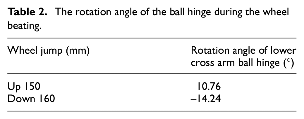
According to the calculation results, the use angle of the suspension ball hinge does not exceed the ±20° angle range specified by the ball hinge product, and the selection of the ball hinge angle meets the design requirements. Therefore, the unreasonable selection of suspension ball hinge angle is ruled out.
The quality of ball hinge is unqualified
The fracture surface of the ball pin was observed under the scanning electron microscope, as shown in Figure 4. The crack initiation area of the cross section mainly showed a worn morphology, with partial fatigue bands, and obvious crack arrest arcs and a large number of fatigue bands in the expansion area. The energy spectrum analysis of the section shows that the material used for the ball pin is low alloy steel containing Cr. The above fracture morphology characteristics indicate that the fracture mode of the ball pin is unidirectional bending fatigue fracture, which originates from the tapered surface of the ball pin.

(a and b) Wear morphology in the source region, (c and d) fatigue band morphology in the extension region, (e) the dimple morphology in the final fracture region, and (f) the energy dispersive spectroscopy on the fracture surface.
Samples were taken at the location of the fracture source area to prepare metallographic specimens for microstructure observation and microhardness testing. The results show that the ball pin matrix structure is tempered sorbite with a hardened layer on the surface, and the depth of the hardened layer is about 0.3 mm, as shown in Figure 5. The microhardness test was carried out on the center of the ball head and the surface hardened layer. The test results are shown in Table 3. The results show that no obvious casting defects are found in the material by SEM analysis, and the microstructure and mechanical properties meet the material standard.

(a) Microstructure of crack initiation region, (b) the morphology of the hardened layer with a total depth of 0.3 mm, and (c) the microstructure in the core area of the ball pin.
Microhardness test results.

Through the observation and analysis of the microstructure of the ball pin, it is considered that: (1) the fracture mode of the ball pin is unidirectional bending fatigue fracture; (2) the surface of the ball pin is corroded; (3) the material of the ball pin is low alloy steel containing Cr, the core is quenched and tempered, and there is a hardened layer about 0.3 mm deep on the surface.
There is no macroscopic material defect on the fracture surface of ball pin. The results of metallographic analysis show that the base structure of the ball pin is tempered sorbite, and there is a hardened layer on the surface. The hardness is HRC56, which meets the technical requirements of suspension ball hinge. Therefore, the unqualified X3 of ball hinge is excluded.
The installation of the ball hinge is not in accordance with the technical requirements
The technical requirements of suspension system: the ball hinge connecting the cross arm and steering knuckle needs to be installed with special tooling. When installing, the thread is coated with thread locking agent LOTITE243, the tightening torque of M100 × 2 thread is 1400–1500 Nm; the tightening torque of nut M42 × 1.5 is 750–800 Nm. After reviewing the assembly process specifications of the ball hinges, it was found that the process cards were prepared in accordance with the technical conditions of the drawings. At the same time, if there is a problem in the installation that causes a crack, the crack will be plastically fractured under the action of external force when the bolt is subsequently press-fitted.
When disassembling on site, the ball hinge is fastened firmly. In summary, the installation of the ball hinge meets the technical requirements, so it is ruled out that the installation of the ball hinge does not meet the technical requirements X4.
Abnormal load caused by abnormal wear of ball hinge
The ball hinge is composed of a ball head seat, a ball pin, a ball bowl and a dust cover. If impurities enter into the ball joint or improper protection leads to grease failure, the ball joint pair will wear rapidly, the clearance will increase rapidly, the ball joint will be loose, and the dynamic load coefficient will increase greatly in the process of use; at the same time, the friction torque between the ball joint and the ball seat will increase due to wear, which will cause the ball pin to bear abnormal load, reduce fatigue life and finally fracture.
Most areas of the ball head surface are bright black, there is obvious corrosion near the conical surface, and some areas are bright gray, which should be caused by wear, as shown in Figure 6. There is a round bright yellow area on the inner surface of the ball socket, which corresponds to the bright gray area of the ball socket, and the wear in this area is more serious than that in other areas.

(a) The light gray area in the ball head caused by severe wear and (b) the corresponding light yellow area in the ball socket.
In conclusion, it can not be ruled out that the abnormal load caused by the wear of the ball hinge leads to the decrease of the fatigue life of the ball hinge and the final fracture X5.
Based on the above analysis, the problem of suspension cross arm ball hinge fracture is preliminarily positioned as: abnormal wear of the ball hinge generates abnormal load, which leads to a decrease in the fatigue life of the ball hinge and finally breaks.
Stress calculation of spherical hinge based on finite element analysis
The ball head seat of the ball hinge is connected with the threaded hole of the suspension cross arm through the thread; the ball joint forms a spherical motion pair between the ball seat and the ball bowl, which can rotate in the circumferential direction around the ball center13,14; the ball pin passes through the taper hole of the steering knuckle and is connected with it, which is fastened by nuts and split pins. The ball joint structure is shown in Figure 7(a).

(a) The assembly of the ball joint structure, (b) the axial force F1 and radial force F2 applied in the ball pin, (c) the stress distribution of the ball head, and (d) the fracture location of the ball pin.
When the vehicle is running, the ball pin bears the combined action of axial force F1 and radial force F2, as shown in Figure 7(b). Through the vehicle simulation of typical limit conditions, the axial force and radial force on the ball head are obtained, and then the finite element analysis of the ball head is carried out, and the stress distribution of the ball pin is obtained, as shown in Figure 7(c). It can be seen that due to the structural characteristics of the ball hinge, the maximum stress on the ball pin is the part of the ball neck at the root of the ball head cone, that is, the minimum section, which is consistent with the actual fracture position of the ball head, as shown in Figure 8(d).

(a and b) Surface corrosion and slight wear morphology of the ball head, (c) high temperature melting ball bowl, (d) there is abrasion and corrosion on the inner surface of the ball head seat, and (e) the macro morphology of the ball bowl after disassembly.
Theoretically, the ball head part of the ball head pin rotates in the ball head seat, and there is grease for lubrication. It should move freely during the working process, and only a small amount of normal wear will occur during use. If the ball head is abnormally worn and the friction pair is poorly lubricated, the friction of the two relatively sliding surfaces will increase, resulting in greater resistance at the top of the ball head pin, and increasing the force on the ball pin neck. At the same time, the wear of the ball head causes the ball head to become loose, the dynamic load coefficient of the ball head is greatly increased, and the force on the neck of the ball also increases. Therefore, abnormal wear of the ball head will cause the ball head to bear abnormal load, reduce the fatigue life and eventually break.
After detection and analysis, most areas of the ball head surface are bright black, and there is obvious corrosion near the conical surface. Some areas are bright gray, which should be caused by light damage. The bright gray area is below the source area, as shown in Figure 8(a) and (b).
The inner and outer surfaces of the ball socket are corroded, and the outer surface is seriously corroded; there is a round bright yellow area on the inner surface of the ball socket, which corresponds to the bright gray area of the ball socket, indicating that the wear of this area is more serious than that of other areas during use. The macroscopic appearance of ball socket is shown in Figure 8(d).
During the disassembly process, the ball bowl was seriously melted and damaged, and there was high temperature melting at the ball bowl corresponding to the fracture source of the ball hinge, as shown in Figure 8(c); the infrared spectrum analysis of the ball bowl material showed that the main component of the ball bowl material was polyvinyl acetal, and the macro morphology of the ball bowl was shown in Figure 8(e).
Analysis of dust cover
The macroscopic appearance of the dust cover is shown in Figure 9(a). The dust cover is damaged and fractured at the root of the installation, and the fracture is uneven around it. There are a large number of cracks on the outer surface near the fracture, some of which are deep and almost penetrate through the wall thickness, and the cracks on the outer surface far away from the fracture are shallow. The inner surface of dust cover is bright black, and no crack is found. The cracks on the surface of the dust cover are rubber aging cracks.

(a) The fractured dust cover with lots of cracks, (b) the crack initiations are located on the outside surface, and (c and d) the tearing morphology on the fracture surface.
The fracture surface is rough and dark gray under stereomicroscope, and the crack initiation area is located on the outer surface, which is multi-source crack initiation, as shown in Figure 9(b). Under the scanning electron microscope, most areas of the fracture surface have no obvious tearing characteristics, which should be the cracking aging crack section; the local area near the inner surface has tearing morphology, which is the aging crack propagation area, as shown in Figure 9(c) and (d).
Therefore, it can be concluded that the rubber dust cover of the ball hinge was firstly aged and cracked, which caused impurities in the ball head, lubrication failure of the ball head, and abnormal wear between the ball head and the ball seat. Then, the friction pair of the ball hinge was not well lubricated in the process of movement. Under the action of friction, the resistance on the top of the ball pin increases, resulting in the increase of the force on the ball neck. Finally, the looseness of the ball head increases the dynamic load on the ball head, reduces the fatigue life and finally breaks.
Conclusions
This paper analyzes the failure of the ball pin of one of the ball hinges after driving more than 50,000 km. The fracture position is located in the stress concentration area at the root of the conical surface of the ball pin, and there is no obvious mechanical damage and plastic deformation trace near the fracture. The rough surface processing grain near the fracture position will aggravate the stress concentration in this area. The fracture surface of the ball pin is flat with metallic luster. The crack initiation area presents wear and fatigue morphology. Several crack arrest arcs and obvious fatigue bands can be seen in the expansion area. No material defects are found on the fracture surface. The above morphologies show that the fracture mode of the ball pin is unidirectional bending fatigue fracture.
After analysis, it is found that the dust cover is aging and cracking in the process of long-term use, resulting in the damage of the dust cover. After the dust cover is damaged, the surface of ball pin, ball head and ball head seat are corroded, and the working face between ball head and ball head seat is filled with sand and other residues. The loss of lubrication in working face leads to the increase of friction and the bending moment of ball pin. Finally, bending fatigue fracture occurs under cyclic loading. The case analyzed in this paper is a typical multi failure mode, including wear, aging, fatigue and so on, which provides support for anti-fatigue design of similar structures in engineering practice.
Footnotes
Handling editor: Chenhui Liang
Declaration of conflicting interests
The author(s) declared no potential conflicts of interest with respect to the research, authorship, and/or publication of this article.
Funding
The author(s) received no financial support for the research, authorship, and/or publication of this article.