
Abstract
A sustainable environment is one of the major challenges in developing countries especially in populated regions due to the industrialization and expansion of urban areas. The industries emit particulate matter into the atmosphere that is harmful to human health. There is a need for an efficient particle separation mechanism to improve indoor air quality. This paper presents a numerical investigation of particles deposition in a square duct with variable roughness elements. The working fluid was taken as a mixture of air and inert particles. The Reynolds Stress Model (RSM) and Discrete Particle-phase Model (DPM) were used to simulate the particle-laden flow to analyze the deposition and velocity of the particles in the duct. The diameter of the particles is taken as 5 µm. The ratio of roughness height to the diameter (r/D) ranged from 0.024 and 0.101 and the spacing to the diameter ratio (s/D) varied between 9.8 and 39.23. It was found that the roughness height has a significant effect on the fluid flow as compared to the spacing between the elements. As a result, more uniform vortices are developed across the elements increasing fluid velocity from 10 to 14 m/s, while the deposition and velocity of the particles were increased by 14% and 8%, respectively. Accordingly, the particles deposition technique helps provide clean indoor air for better environmental sustainability.
Keywords
Introduction
The environmental issues are consistently increasing due to the pollution and ecosystem. The impact of human activities on the environment is also grown up because of the increase in world population, urban areas, industrial activities, and energy consumption. Energy use in different forms highly affects the world locally as well as globally. 1 The urban areas are more populated and therefore, the large energy consumption occurs in the cities. Energy is the main concern in both developed and under-developing countries due to the increase in global challenge. Environmental energy conservation is secured by making different policies to meet the requirement of energy in the world.2,3 The global energy consumption is increased in all over the world due to which the environmental issues are increased. 4
As a result of high energy utilization, particulate matter in the atmosphere has become a major source of pollution in urban areas due to the rapid increase in industrialization, the number of vehicles, and energy consumption. The outdoor dust particles enter the houses and buildings through the air conditioning and ventilation system. These particles are dangerous to human health, especially, for those with asthma and respiratory problems. Most people spend almost 20 h per day at indoor places, it becomes a serious concern and equally important to improve the indoor air quality by removing the dust particles from the air.5,6
The particles in the air are highly affected by turbulence causing dispersion or clustering depending on the size of the particles and fluid characteristics.7,8 There exist different ways to remove the inertial particles from the air by enhancing turbulence and the particles deposition using roughened surface of the duct is one of the emerging techniques. The particles deposition can be applied to the industrial applications such as, fluid flowing in the channels where the particles may cause blockage of passage.
The deposition of particles process in the ducts have been examined both by using the numerical simulation as well as experiments. 9 Direct numerical simulation was used to study the effect of the rough surfaces on the particles induced in a turbulence modulation for spatially developing the boundary layer.10,11 The immersed boundary method was used to analyze the hemispherical roughness on the wall surface and both the particles and fluid were resolved by Eulerian and Lagrangian approaches.11,12 It was found that, for small particles, the deposition rate in the horizontal channels depends on the wall roughness and water flow rate while the temperature differences and gravity become more significant factors for large-sized particles.13,14 In the current work, the effect of rough surfaces on the deposition of small particles is investigated.
The shape and size of roughness elements introduced in the duct is an important parameter controlling the deposition process. The effect of two-dimensional (2D) and three-dimensional (3D) irregular, rough surfaces inside the channel for fully turbulent was investigated using Large Eddy Simulation (LES). Three-dimensional rough surfaces have a greater impact because they showed the clear span-wise heterogeneity of the flow.15,16 The particulate flow was investigated in a developing turbulent boundary layer over the hemisphere roughened wall using DNS and Eulerian and Lagrangian approach. 9 The results obtained emphasized the significance of wall roughness near the wall which can increase the vorticity by 25%. Similarly, the coherent structures through a square elements were numerically studied using DNS and reported that the transition in phase occurs due to opposing walls.17,18 The particle deposition rate was numerically investigated to examine the effect of different types of roughness elements and the results showed the significance of roughness elements for the particles deposition and deposition velocity.19–21
The deposition rate of particles strongly depends on Reynolds number, shape of roughness element, and size of the duct.22–24 Further to this, flow characteristics and turbulence intensity also affect the deposition process. An increase in the Reynolds number increases the deposition rate of particles. 25 The particle agglomeration near the wall was observed and it was influenced by the turbulence intensity.26–28 Milici et al. investigated the particle-laden flow in a vertical duct by using the Lagrangian pointwise tracking method with DNS and their results revealed that the turbulence intensity increases and the velocity of the fluid decreases along the wall-normal direction.25,29
The deposition of ultrafine particles by inserting the twisted tap inside the duct was studied and described that the friction factor of the duct with twisted tape is greater than the empty duct by 8%. 18 The turbulent flow through a channel with rigid and flexible roughness was examined using a digital inline holographic particle tracking method and found that the effect of roughness is very significant on the particle motion. 29 The numerical investigation of spherical particles in a square duct was performed. The comparison of the velocity field was made by using particle image velocimetry and particle resolved direct numerical simulation.30,31 The results obtained were the particle interaction with minimum near the flow field because the particle made a cluster and not provide the space for penetration.
The particulate flow in a duct with roughness elements have been studied by applying different turbulence models and particle tracking methods. The particles deposition process was used with different types of roughness elements. It was observed that the deposition of particles across the sharp edges of rectangular and triangular shape of rough elements was not uniform and therefore, the pressure drop across the duct is relatively high. In this study, a modified shape of two-dimensional roughness elements of flattened triangular shape is chosen in a square duct to study the particles deposition. The Reynolds Stress Model (RSM) and Discrete Particles-phase Model (DPM) are employed to simulate the particle deposition process. The height of roughness elements and the spacing between elements are considered to analyze the effect of roughness on the fluid flow as well as on particles deposition. As the results of local turbulence effect around the roughness elements, the particles are deposited on the roughness elements, and hence improving the air quality for indoor applications.
Methodology
Physical model
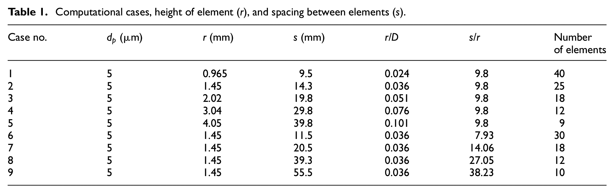
The schematic of two-dimensional roughened square duct and the geometrical shape of the rough elements inside the duct are shown in Figure 1(a) and (b) respectively. The length of the duct is 800 mm with internal diameter of 40 mm. For the development of fully turbulent flow, the first half of the duct remains smooth and the rest of the length is introduced with roughness elements. These elements are uniformly arranged with constant spacing. The ratio of spacing to height of roughness s/r is ranged from 9.8 to 39.23 and height of element to the duct diameter r/D lies between 0.024 and 0.101. Table 1 presents the detailed parameters of different test cases.

(a) Two-dimensional model of a square duct and (b) dimensions of roughness element.
Computational cases, height of element (r), and spacing between elements (s).
Fluid flow continuous phase modeling
The turbulent flow can be considered as an incompressible gas flow due to very low velocity of air stream. The mass and momentum equations are given in equations (1) and (2),

where
The turbulence effect was incorporated into numerical model using a Reynolds stress turbulence model which is given by equation (3),

Particle motion discrete phase modeling
The discrete particle phase model was used to model the particles inside the duct. The volume of the particle is less as compared to the air volume so the effect of particles on the turbulence of airflow and collusion between particles is neglected.21,32 The particles to gas density ratios are very large therefore the force of the pressure gradient and virtual mass cannot be considered. The rotation and collision of the particles are ignored. All the particles are considered as solid spheres. The Brownian effect is neglected.
The phase equation of the particles is given in equation (4)

Here,
Particles deposition ratio and deposition velocity
For the computation of deposition velocity mostly non-dimensional velocity is considered for the calculation. In this study, the deposition velocity is defined as,

Where the

Here

Where,
The non-dimensional particles relaxation time is given as
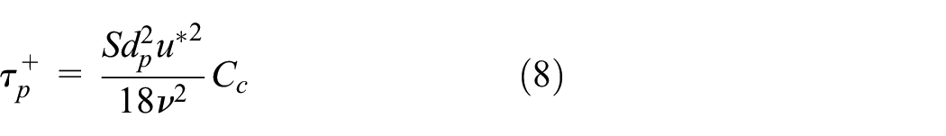
Where S is the particle to fluid density ratio, and give as; S =
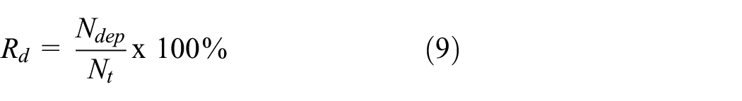
The deposition ratio of the particles can be calculated by the formula given as,
Where,
Boundary condition and solution methods
The velocity and pressure at the inlet and outlet were chosen to set the boundary conditions for the analysis. The no-slip boundary was set for the wall surface and enhanced wall treatment was used to simulate the near-wall characteristics of the fluid. For this purpose, the scalable wall function was used in the Reynolds stress model. If the flow field region was in the range of Re ≥ 400 then the traditional turbulence model like k-epsilon and k-omega is used for the simulation and if the flow field region is in the range of less than Re ≤ 400 then the viscous laminar model is used to simulate
The Reynolds number is given in equation (10),

The enhanced wall treatment can also be used for that purpose but in the case of enhanced wall treatment, the roughness height will be constant. The turbulent diffusion rate is given in equation (11),

For the discrete particle model, 40,000 inert particles released from the inlet of the square duct having 700

Where n is the size distribution parameter, d̄ is the size constant, and d is the diameter of the particles.
The Discrete Random Walk Model can also be used to calculate the effect of the instantaneous velocity of the trajectories of the particles.35–37 For the time scale, the equation is given as,

Mesh independence
The meshing of the physical model is done by changing the size of elements and the whole structure is meshed with a grid resolution. A meshed model is presented in Figure 2. In the fully turbulent flow, the mesh refinement technique is used near the 2D roughness elements and the boundary layer obtained in the turbulent flow is very consistent. A maximum value of roughness height and different sizing parameters are applied for the mesh validation of case 5 as mentioned in Table 1.

Meshed model with discretized structure.
Five different mesh numbers are tested against the average velocity of the flow. It was observed that, after the mesh number 5 ×
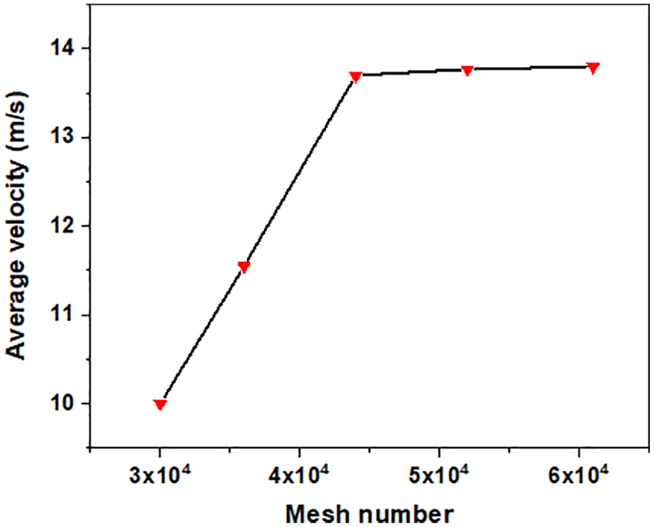
Mesh independence analysis based on average air velocity.
Model validation
The validation of the model is done by simulating the fluid flow near the wall and rough elements. It is found that two large eddies produced across the roughness elements as presented in Figure 4. One is produced before the roughness element while the second vortex is formed after the roughness element. The later eddy is larger in eddy length (L2) as compared to one formed before roughness element (L1).

Eddies produced in the duct around the rough elements.
The eddy length to the diameter ratio is compared with previous studies. Lohaz et al. perform simulation analysis of particulate flow by applying Large Eddy Simulation method and found the results for eddy length to diameter ratio are 4.12 and 1.06 for both eddies, respectively. 38 Similarly, Hong et al. 5 investigated the eddy formation process in the ductwork system by using Reynolds stresses model and the results obtained are 4.1 and 1 eddy length to diameter ratio for the eddies produced, respectively. The results obtained in present work are very much comparable as shown in Table 2 and the model used is applicable for further use with various flow conditions. Moreover, the ratio of eddy length to diameter is of greater value as compared to previous studies; therefore, the particles have enough space to be deposited on the surface of the duct due to larger eddy region.
Comparison of eddy length to roughness height ratio with previous studies.

Results and discussion
A mixture of air and particles with a constant diameter (dp) of 5 µm are allowed to enter into a square duct. The fluid flow in the duct is fully turbulent and the velocity profiles in the smooth and rough sections are plotted in Figure 5. It can be seen that the rough elements have an effect on the original boundary layer produced in the duct. At the length L = 400 mm, the boundary layer is changed and the boundary layer thickness increases as the increase in roughness. The particles in the air tend to deposit on the wall of the duct and this effect of deposition is enhanced by introducing the roughness elements. The number of particles deposit on the roughness element depends on height of roughness elements as well as the spacing between two consecutive elements. In the following sections, the effects of these variables on the fluid velocity and deposition ratio have been explained in details.

Velocity streamline in square duct with half roughened surface.
Effect of roughness element on fluid velocity in the duct
The two-dimensional roughness elements increase the air velocity in the duct due to the low-pressure regions just behind the elements. The boundary layer produced in roughened part of the duct becomes thicker as compared to the smooth section. The change in flow velocity was observed with varying roughness element height and spacing between the elements. When the r/D value is increased keeping constant value of s/r, the flow velocity through duct increases, and reaches an optimum value as shown in Figure 6(a). On the other hand, the maximum fluid velocity is decreased with the increasing value of s/r keeping the value of r/D constant and shown in Figure 6(b).

Maximum flow velocities with different values of (a) r/D and (b) s/r.
Figures 7 and 8 show the velocity distributions in the duct for different height to diameter and spacing to the height ratios, respectively. It is clearly observed that high velocity can be achieved around the roughness elements by increasing the height to diameter ratio.

Velocity streamlines with increasing value of “r/D” with a constant s/r = 9.8: (a). r/D = 0.036 and (b) r/D = 0.051.

Velocity streamlines with increasing value of “s/r” with a constant r/D = 0.036: (a). s/r = 7.93 and (b) s/r = 14.06.
Similarly, the velocity distribution becomes relatively irregular and a weak boundary layer is developed with increasing values of spacing to height ratio of the elements. The extended vortices across the element allow the particles to sweep through the duct and tendency of deposition of the particles is reduced.
Effect of roughness element on the particle deposition ratio
The effect of height and spacing of roughness elements has been analyzed based on the fluid flow and deposition of the particles. The mixture of air and inert particles is considered as a two-phase flow and the case 5 from Table 1 is chosen for the detailed analysis of particle deposition. It is found that a more number of particles are deposited on the first roughness element as compared to any other element. The deposition of the particles increases as the value of roughness height increases as shown in Figure 9(a). The enhancement in particles deposition is due to increase in the surface area. When the surface area of roughness element increases, the particles find more space to deposit. The deposition ratio becomes a maximum of almost 14% when the value of roughness r/D is 0.101 with the constant value of s/r.

Deposition ratio of the particles with different values of (a) r/D and (b) s/r.
On the other hand, Figure 9(b) shows an inverse relation between the spacing between the elements and the deposition of particles on the rough surface. It is due to the fact that the spacing between elements decreases the strength of vortices across roughness element and as the result, less number of particles deposited in the duct. When spacing is increased the particles are also deposited on other surfaces and escape through the outflow of the duct, but as compared to the rough surface the deposition of particles is almost five times less.
Effect of roughness on the particle deposition velocity
The deposition velocity of the particles is another important parameter which is considered as the non-dimensional velocity. It is used to find the accurate value of particle deposition velocity and particle deposition relaxation time. The particles relaxation time is plotted with non-dimensional velocity to verify the results with previous research 5 as shown in Figure 10. The model was applied to predict the particle deposition velocity in this work.

Non-dimensional deposition velocity comparison.
The particle’s non-dimensional velocity increases as the value of roughness height increases. The non-dimensional velocity is represented by

Non-dimensional velocity with different values of (a) r/D and (b) s/r.
Conclusions
The roughness elements with flattened triangular shapes were introduced in a square duct to study the particles deposition for improving the indoor air quality. The particle-laden flow was simulated and the deposition of particles in a square duct with different values of roughness height and spacing was investigated. The fluid velocity increased and was more streamlined as compared to conventional triangular and square roughness elements used in Hong et al., 5 causing an increase in boundary layer thickness. Overall, a 30% increase in maximum velocity of fluid was observed with an optimized element height to diameter of the duct ratio of 0.101.
It was found that the roughness height has a significant effect on the particles deposition ratio. With the increase in height of roughness elements, the enhanced turbulence effect forced the particles to deposit on the rough surface. Using the optimum height of the roughness element, a 14% increase in deposition ratio is achieved. Similarly, the particle deposition velocity also increases up to 10% with the increase of relative roughness height. On the other hand, the increase in spacing between two consecutive roughness elements reduces the particles deposition.
In the current work, the variation in height of roughness elements shows a strong correlation with the deposition of particles in a ducting system having a number of roughness elements along the wall. It is recommended to continue this study for a range of air velocity at the inlet of the duct as well as with an enhanced number of particles to air volume. Further, it would be interesting to compare the simulation results with the state of the experimental results in the future.
Footnotes
Appendix
Handling Editor: James Baldwin
Declaration of conflicting interests
The author(s) declared no potential conflicts of interest with respect to the research, authorship, and/or publication of this article.
Funding
The author(s) received no financial support for the research, authorship, and/or publication of this article.