
Abstract
Regular safety inspections are an important guarantee to ensure the high-quality operation of concrete structures of tunnels. The Chinese West-east Gas Pipeline Project is large in scale and complex in construction environment. These tunnels are equipped with gas pipelines, and the concrete structural defects of the tunnels are continuously exacerbated during the long-term operation. There are few studies on the safety evaluation methods of concrete structures of gas tunnels. Based on the characteristics of the operation of the gas tunnels, this paper proposes the establishment of a structural safety comprehensive inspection system from the following seven aspects, that is, the void between the concrete lining and surrounding rock, the strength of the concrete lining, the thickness of the protective layer of the reinforced concrete lining, the carbonization depth of the concrete lining, the deformation of the tunnel section, the cracks in the concrete lining, and the auxiliary concrete structure of the tunnel. In addition, a corresponding quantitative determination method and safety level classification standard are established. Based on the fuzzy mathematics theory and a structural safety comprehensive inspection system, a five-level safety evaluation method for tunnel concrete structures is proposed. Finally, a comprehensive inspection and evaluation were carried out for a tunnel running across the mountain.
Introduction
Regular safety inspections are an important guarantee to ensure the high-quality operation of concrete structures of tunnels. The Chinese West-east Gas Pipeline Project is large in scale and complex in construction environment, which involving many tunnels built across mountains or rivers. The defects in the concrete structures of these tunnels are constantly exposed during a long-term operation. Particularly for some of the tunnels that have not been regularly inspected since their completion, the safety hazards of their concrete structures cannot be detected in time. These safety hazards include concrete lining cracks, void between the concrete lining and surrounding rocks, water seepage, and damage to the pipe buttress, which seriously affect the quality and safety of the tunnel operation.
Safety inspections and evaluations during the operation period are mostly conducted for railway, highway, and subway tunnels,1–5 whereas for gas pipeline tunnels, the focus of the inspections and evaluation of their concrete structures are different. For example, the void behind the concrete lining of the tunnel and the damage to the auxiliary structures that are likely to cause damage to the gas pipelines are more important than other factors. A number of studies have been carried out on the determination and evaluation of different defects in the concrete structures of gas pipeline tunnels. For example, Luo et al. 6 conducted a study on an assessment method of the vulnerability of gas pipeline tunnels, while Yang et al. 7 established a model to assess the tunnel collapse risk based on the factors that caused the tunnel collapse. However, the above studies either detect or evaluate certain conditions of the concrete tunnel structures (such as concrete cracks and the strength) or evaluate tunnel disasters or potential dangers. The measurement of defects in concrete tunnel structures is a complex process, which needs to take into consideration multiple indicators for a comprehensive judgment. A single method will compromise the comprehensiveness of the measurement results. At the same time, it is necessary to solve the difficulties of relying on not merely a qualitative evaluation but also a quantitative evaluation. A comprehensive evaluation refers to the systematic and holistic evaluation of an object related to multiple indicators. Commonly used evaluation methods include the analytic hierarchy process (AHP) and a fuzzy comprehensive evaluation method. 8 The AHP is a quantitative method for a comprehensive evaluation involving multiple indicators. Its basic principle is to compare the relative importance of the factors to be evaluated and determine the weight for each factor. 9 A fuzzy comprehensive evaluation is an evaluation method based on fuzzy mathematics theory. It evaluates the research object based on the known evaluation standards and actual measurement data of the related indicators, which have undergone a fuzzy transformation. 10 The researchers have applied the above two methods to carry out extensive studies on the evaluation of the operating conditions of highways and railway tunnels.8,11–13 The concrete structures of a gas pipeline tunnel usually include concrete lining and auxiliary structures such as anchor piers and pipe buttresses. The structure is relatively dispersed, and the results of a pairwise comparison with the AHP are usually inconsistent. By contrast, the fuzzy comprehensive evaluation method can be used to quantitatively evaluate a complex multi-level multi-objective indicator system, which includes many quantitative and non-quantitative factors.
Regarding the comprehensive inspection of the concrete structures and the overall operation status of the gas pipeline tunnels, there is still a lack of a complete set of inspection system and evaluation methods, with deficiencies in the selection of evaluation indicators and the reasonable quantification of these indicators. Based on an extensive analysis of the multiple tunnels of the Chinese West-East Gas Pipeline, this paper uses the criteria for determining the safety status of concrete structures such as highway tunnels and railways to develop a safety inspection system and comprehensive safety evaluation methods for concrete structures of gas pipeline tunnels. (1) A safety inspection system, including inspection items and corresponding inspection methods, has been established based on the possible defects in the concrete structure. (2) The quantitative determination method and safety level classification standard of each inspection item are established. (3) The indicators are extracted based on the safety inspection system, and a comprehensive safety evaluation method of tunnel concrete structures based on fuzzy mathematics is proposed to allow an understanding of the quality of the tunnel concrete structure from the parts to the whole. Finally, a comprehensive inspection and safety evaluation method is applied to a tunnel section of the Nanchang-Shanghai Branch of the Chinese West-East Gas Pipeline to inspect and evaluate its concrete structures and provide suggestions for future maintenance and repair of the concrete structures of the tunnel.
Comprehensive inspection system and classification standards for tunnel concrete structures
The construction of the inspection system is based on the in-situ inspection experience and related research.14–21 Firstly, the structures that affect the safe operation of the gas pipeline tunnel are found, including the concrete lining and auxiliary structures like pipeline anchor buttress and pipeline buttress. Secondly, the possible defects of the concrete lining and auxiliary structures are analyzed. Finally, the severity of these defects based on the test results is summarized. The next seven indicators are selected as the safety comprehensive inspection system, including the separation between the concrete lining and surrounding rock, the strength of the concrete lining, the thickness of the protective layer of the reinforced concrete lining, the carbonization depth of the concrete lining, the deformation of the tunnel section, the cracks in the concrete lining, and the auxiliary civil structure of the tunnel. Then the criteria of these indicators are calculated by both considering their impact on gas pipeline and referring to the different tunnel inspection standards.22–33 The overall inspection items and inspection methods of the tunnel concrete structures are shown in Figure 1.
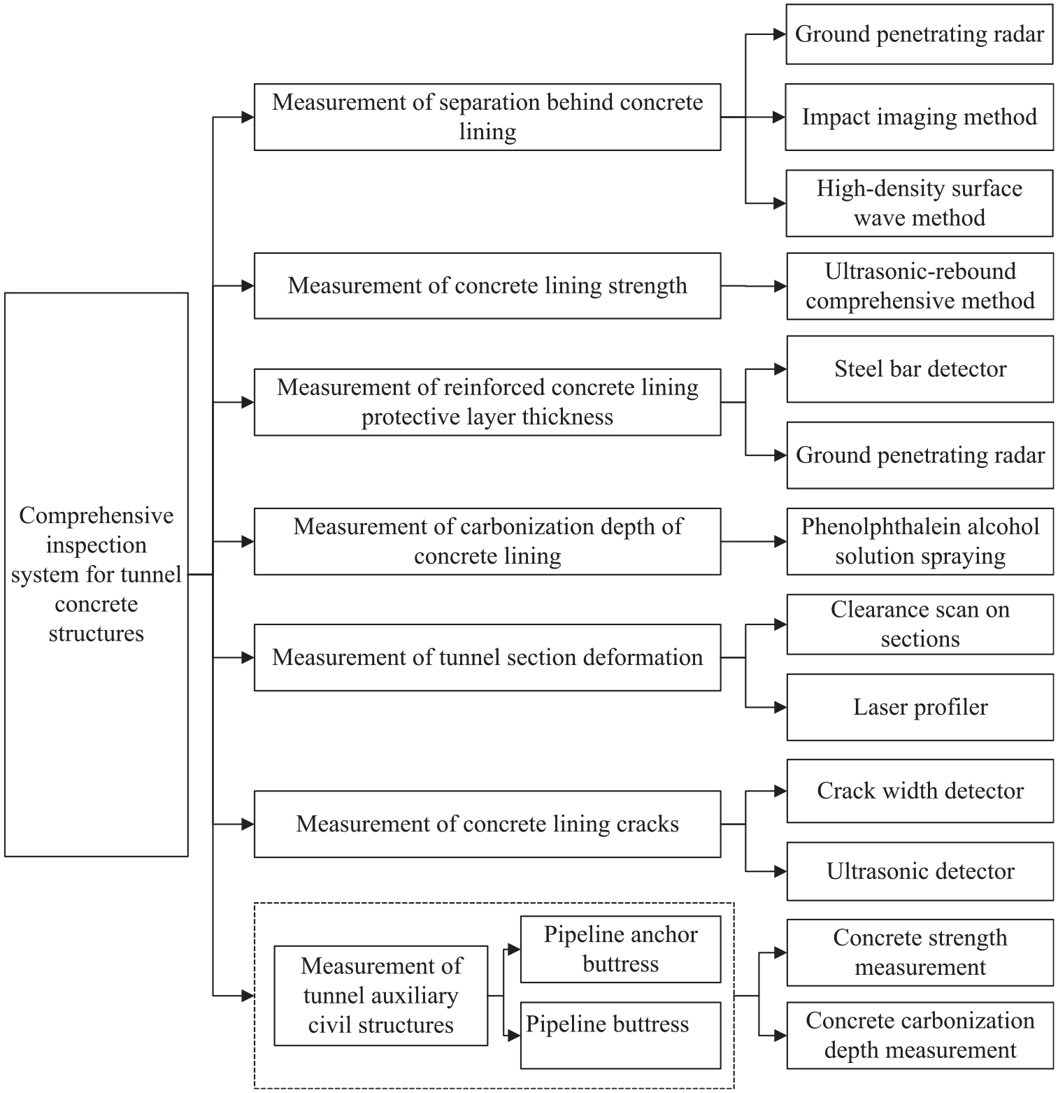
Comprehensive inspection system for concrete tunnel structures.
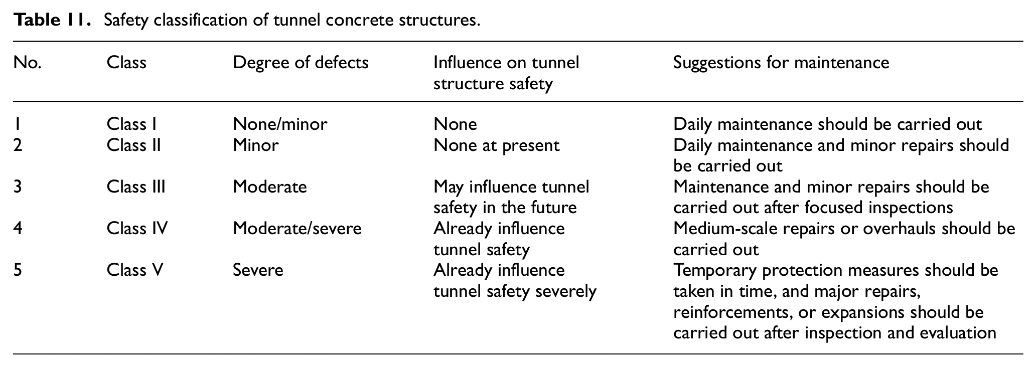
The evaluation criteria are classified into five grades, because first of all, every grade should corresponding to a suggestions for maintenance, the suggestions are generally divided into five level according to severity, namely daily maintenance, daily maintenance and minor repairs, maintenance and minor repairs should be carried out after focused inspections, medium-scale repairs or overhauls, and temporary protection measures should be taken in time, and major repairs, reinforcements, or expansions should be carried out after inspection and evaluation.. Secondly, the evaluation method we proposed should be able to be used in the in-situ inspection, so it should be consistent with the evaluation criteria of most the inspection standards.
Measurement of separation behind concrete lining
The gas pipeline tunnel has gas pipelines arranged in it. The hazard owing to the separation behind the concrete lining is much higher than that of other inspection items because the falling rock caused by the separation can lead to pipeline damage. A common method to detect the separation in concrete structures in engineering uses ground penetrating radar (GPR), which creates a judgment based on the difference in the reflected signals caused by the difference in the dielectric constants of the media. 34 Although the efficiency is high, this method cannot meet the on-site inspection requirements when the tunnel structure contains metal or reinforced concrete, or the site contains water. As non-destructive testing methods based on an elastic wave reflection and a Rayleigh wave detection, the impact imaging method 35 and high-density surface wave method 36 have the advantages of a fast data collection and adaptability to a wide range of working environments. Therefore, the following classifications of inspection methods are determined. (1) For the measurement of separation behind the concrete lining of tunnels in dry regions of waters and mountains, GPR, an impact imaging method, and a high-density surface wave method can be used. (2) For tunnels under a water sealing operation, the measurement for a concrete lining separation after the tunnels are drained can use the impact imaging method or the high-density surface wave method. (3) For cross-sections containing steel bars, the impact imaging method or the high-density surface wave method can be used for a separation measurement. The ratio t1 of the area of the separation area behind the concrete lining to the area of the total inspection area, and the ratio t2 of the average separation height to the total height of the lining are used as the control indicators. Taking into consideration the hazard of the separation behind the lining to the gas pipeline tunnel, the evaluation criteria should be stricter than other types of tunnels, which should meet the requirements listed in Table 1.
Separation evaluation criteria.

Measurement of concrete lining strength
In the safety inspection of concrete lining, the strength is a basic requirement. 37 This paper proposes adopting the relative change C in strength of the concrete measurement area with respect to the design strength as a quality evaluation indicator of the concrete lining strength. For tunnels under a water sealing operation, a measurement of the strength of the lining concrete is carried out after the tunnel is drained. During the inspection, the measurement area needs to be relatively flat and clean, without honeycombs, pockmarked surfaces, cracks, peeling, or spalling. For areas with local unevenness and water, measures such as sanding and drying should be taken. Table 2 lists the quality evaluation criteria for the strength of concrete lining developed in this paper.
Quantitative evaluation criteria of change in concrete strength.

Measurement of protective layer thickness of reinforced concrete lining
The thickness of the protective layer of a reinforced concrete lining can not only be used as one of the factors along with the carbonization depth to evaluate the corrosion status of the steel bars, it can also reflect the construction quality. In engineering practice, if the thickness of the reinforced concrete protective layer is not designed and constructed in accord with the requirements of the relevant specifications, quality problems in concrete components or structures can easily occur, which will affect the performance and safety of the structures. For tunnels under a water sealing operation, the thickness measurement of the protective layer of the reinforced concrete lining should be carried out after the tunnels are drained. The corresponding measurement of the concrete thickness is carried out on the selected measurement area, and the ratio of the designed protective layer thickness to the measured protective layer thickness is calculated, which is defined as the ratio of the insufficient thickness of the protective layer d. The protective layer thickness should meet the requirements listed in Table 3.
Evaluation criteria of insufficient concrete protective layer thickness.

Measurement of concrete lining carbonization depth
The carbonization of concrete refers to the neutralization reaction in which the acid gas, CO2, in the air reacts with the liquid-phase alkaline substances in the concrete, which reduces the alkalinity and changes the chemical composition of the concrete. For reinforced concrete, when the carbonization depth is greater than the thickness of the protective layer of the concrete, the steel bars will lose the protection of the alkaline concrete environment and become prone to corrosion. The quantitative evaluation criteria of the concrete carbonization depth indicator are shown in Table 4.
Quantitative evaluation criteria for concrete carbonization depth indicator.

Measurement of tunnel section deformation
Tunnel section deformation includes a deformation of the tunnel cross section and longitudinal section. A cross-sectional deformation is measured by the ratio of the change in the radial direction of the tunnel cross section in the measurement area to its designed inner diameter, which is calculated through the following formula:

where μ[D] is the change in the cross-sectional diameter; ΔD is the change in the radial direction of the measurement area; and D is the designed inner diameter of the tunnel.
For non-circular tunnels, the changes in the vertical and horizontal directions are calculated separately, and the more unfavorable value is taken. The evaluation criteria for the tunnel cross-sectional deformation control are shown in Table 5.
Evaluation criteria for tunnel cross-sectional deformation control.

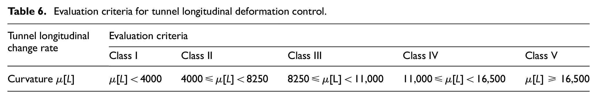
The longitudinal section of the tunnel refers to the projection on the vertical plane extending along the centerline of the tunnel. The deformation of the longitudinal section is determined by calculating the radius of curvature of the longitudinal deformation curve. The evaluation criteria of longitudinal deformation indicator are shown in Table 6.
Evaluation criteria for tunnel longitudinal deformation control.
Measurement of concrete lining cracks
The existence of cracks will reduce the integrity, impermeability, and durability of the concrete tunnel. The inspection items for cracks should include the distribution, length, width, and depth of the cracks, and the depth should be measured where the crack is the widest. The crack depth evaluation of the tunnel concrete lining should meet the requirements of Table 7.
Evaluation criteria of lining cracks.

Measurement of tunnel auxiliary civil structures
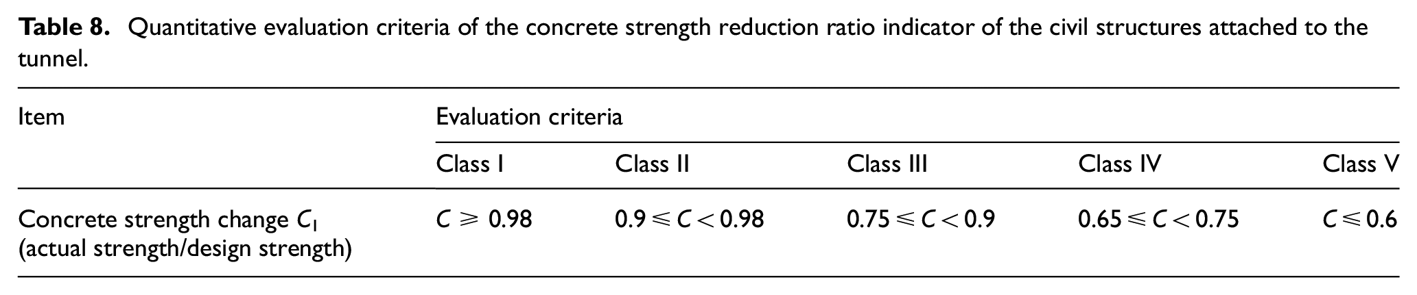
In addition to the concrete lining of the gas pipeline tunnel, there are some concrete structures that require regular safety inspections, including pipeline anchor buttresses and pipe buttresses. These structures are as important as the separation behind the concrete lining because serious damage to the auxiliary structures can cause deformation or even damage to the gas pipeline. The inspection items include the concrete component strength and concrete carbonization depth, and the methods are as described in Sections 3.2 and 3.4. Considering the importance of the auxiliary civil structures to a gas pipeline tunnel, the evaluation criteria should be stricter than for other types of tunnels. The concrete strength evaluation of the auxiliary civil structures of the tunnel should meet the requirements in Table 8, and the evaluation criteria of the carbonization depth should meet the requirements in Table 9.
Quantitative evaluation criteria of the concrete strength reduction ratio indicator of the civil structures attached to the tunnel.
Quantitative evaluation criteria of the concrete carbonization depth indicator of the civil structures attached to the tunnel.

Fuzzy comprehensive safety evaluation method for concrete tunnel structure
Fundamental theory
The fuzzy comprehensive evaluation method uses the theory of fuzzy mathematics to evaluate the research object through fuzzy transformation of the known evaluation standards and relevant measured data. This method considers the contribution of different indicators to the final judgment result, assigns larger weights to more influential evaluation indicators, and reduces the impact of non-important indicators on the results. Hence, it is suitable for a multi-factor, multi-level, and multi-objective safety evaluation of gas tunnel concrete structures during operation. In the fuzzy comprehensive evaluation, the maximum degree of membership is generally used to process the evaluation indicators. 38 Determining the degree of membership (with the membership function) has a vital influence on the rationality of the fuzzy comprehensive evaluation results.
Procedure of fuzzy comprehensive evaluation method
Establish evaluation object factor set and evaluation set
The factor set is a general set U composed of various factors that affect the evaluation object, that is, U = {u1, u2,…, un}, where um represents a single typical factor. The evaluation set is a set V composed of evaluation levels, that is, V = {v1, v2, …, vn}, where each element vn represents each evaluation level.
Establish factor weight set
The weight set reflects the importance of each factor. The set A = {a1, a2,…, am} composed of each weight can be seen as the degree of membership of each factor um to the evaluation set. In this paper, weighting is carried out according to how much each evaluation factor exceeds its standard value. The greater the excess, the larger the weight value. The weight of any general factor is calculated according to the following formula:
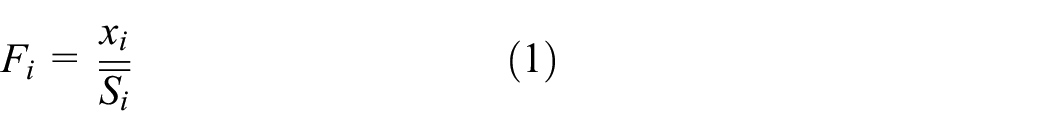

where Fi represents the factor weight, xi represents the actual measured values of the i-th evaluation factor from the bottom,
To conduct fuzzy calculations, each individual weight must also be normalized. The calculation formula is as follows:

where
Establish membership function
There are many commonly used membership functions. When every evaluation level corresponding to an indicator can be represented by a closed interval of real numbers, a certain typical fuzzy distribution function can be selected according to the actual problem to determine its degree of membership. Common fuzzy distribution functions include a half-rectangular distribution and rectangular distribution, half-trapezoidal and trapezoidal distribution, K-th parabolic distribution, T-shaped distribution, and normal distribution. Because the factors selected in this paper increase in their standard values along with the level, the descending half-trapezoidal distribution function is used.
The i-th element in the factor set is denoted as ui, and its degree of membership to the j-th element vj in the evaluation set is denoted as rij. In this paper, the descending half-trapezoidal membership function is used to establish the membership function rij of each evaluation factor to each standard level, thereby establishing the fuzzy relationship matrix R = (rij). The formula for calculating the membership is as follows:
At the first level, that is, when j = 1,

At the second, third, and fourth levels, that is, when j = 2, 3, 4,
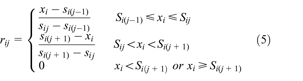
At the fifth level, that is, when j = 5,

where rij represents the fuzzy relationship matrix, xi represents the measured value of the
Selection of evaluation factors
The establishment of reasonable evaluation factors is the basis for a quantitative evaluation of the safety of tunnel concrete structures. During the selection of the indicators, problems such as an excessive or insufficient number of indicators and an overlap of information between indicators should be avoided. The selection of evaluation factors should be based on the principles of completeness, simplicity, independence, and operability. 13
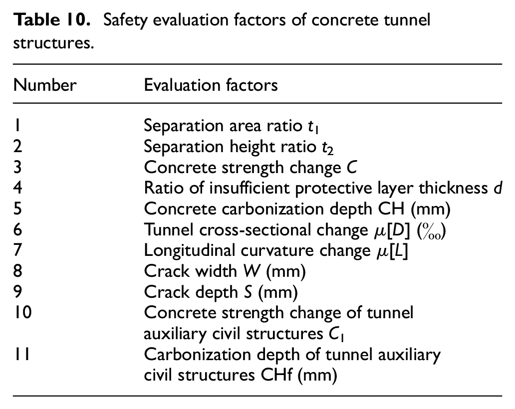
It can be seen from the fuzzy comprehensive evaluation method that the importance of each evaluation factor in the fuzzy comprehensive safety evaluation is mainly reflected by the factor weight. When the evaluation criteria of each factor are more stringent, the factor will be more important in the fuzzy comprehensive safety evaluation. Therefore, according to the classification standards of the comprehensive inspection system for tunnel concrete structures, factors such as the separation rate behind the concrete lining, concrete strength of auxiliary civil structures, and carbonization depth of the tunnel have a relatively stronger influence on the evaluation results. According to the selection principle of the evaluation indicators, in view of the 7 aspects considered in the comprehensive inspection system of the concrete tunnel structures, 11 evaluation factors are selected as shown in Table 10.
Safety evaluation factors of concrete tunnel structures.
Classification of evaluation
The proposed quality and safety classification standards are the same as the evaluation criteria of each indicator. The details are shown in Table 11.
Safety classification of tunnel concrete structures.
Application
Project overview
The case study is conducted with a certain tunnel section of the Nanchang-Shanghai Branch of the Chinese West-East Gas Pipeline, located in Xiaoshan District of Zhejiang Province. The designed starting and ending points of the tunnel section are at 638.9984 and 639.6002 km of the entire branch, respectively, with a horizontal length of 602 m and a measured length of 608.9 m. The longitudinal slope of the tunnel follows a straight-line design, with a slope of approximately 1.58%. The cross section of the tunnel has dimensions of 3.0 m × 3.0 m (width × height). The relative difference in height of the tunnel is approximately 127 m with poor visibility. The slope of the mountain is between 25° and 35°, with well-developed vegetation and no large gullies. According to preliminary survey results, there are many leaks in the tunnel, showing water seepage, sand leakage, mud leakage, and white crystal precipitation. There are also multiple leaks at the joints of the concrete lining, as shown in Figure 2.
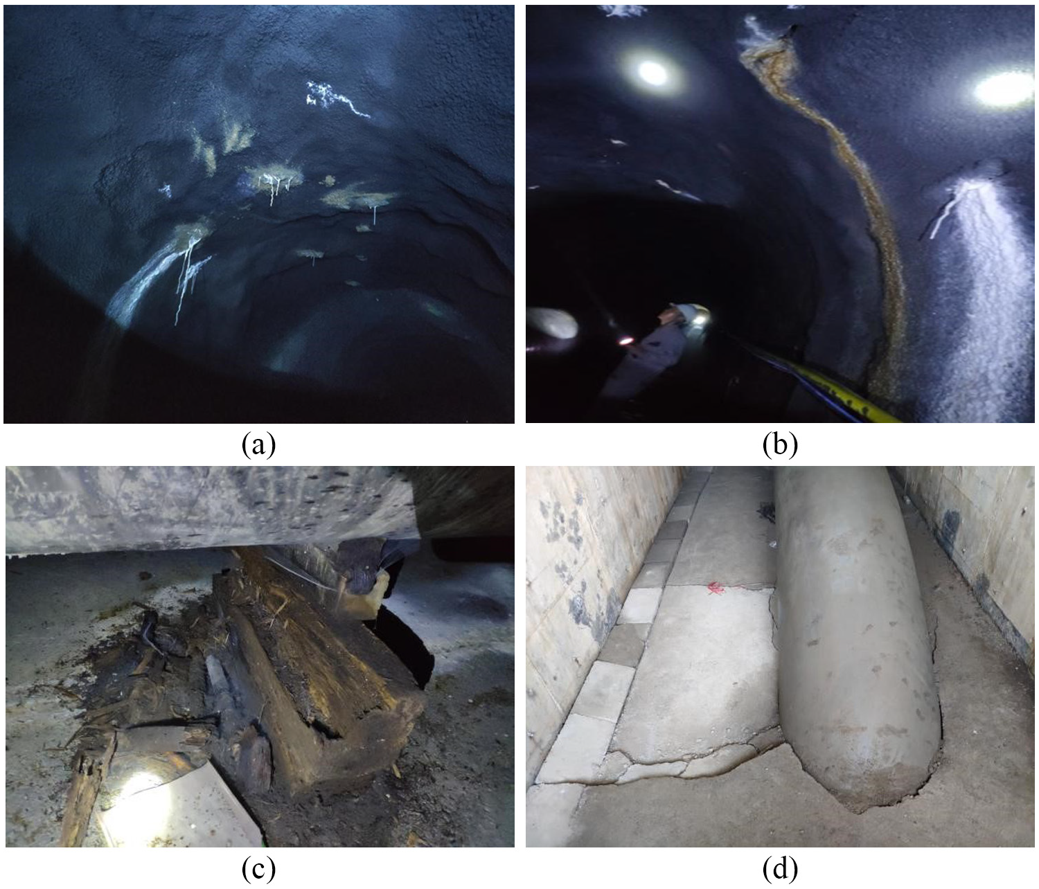
Current status of tunnel: (a) water leakage and white crystal precipitation in the arch, (b) water leakage and yellow substance precipitation in the arch, (c) corroded buttress, and (d) damaged/sunk bottom plate.
Tunnel inspection results
Measurement of separation behind concrete lining
The separation behind the concrete lining of the tunnel is detected comprehensively using GPR, an impact imaging method, and a high-density surface wave method. According to the onsite conditions for the measurement, the layout of the measurement lines of each method is shown in Figure 3. There are seven measurement lines for the GPR (denoted by the numbers in red), five measurement lines for the impact imagining method (denoted by numbers in magenta or blue), and one measurement line for a high-density surface wave method (denoted by the number in blue).

Schematic of measurement lines for separation behind concrete lining.
Figure 4 shows the measurement results of a typical tunnel section obtained using an impact imaging method, a high-density surface wave method, and a GPR method. With the impact mapping method and high-density surface wave method, images express the degree of compactness of the lining structure through the cold and warm colors, such that the colder the color, the more compact the lining structure and vice versa. Based on the measurement results of the impact imaging method, high-density surface wave method, and GPR method, separation exists in the tunnel. In particular, a severe separation is detected between K0 + 190 and K0 + 204 and between K0 + 508 and K0 + 535 of the right vertical wall, between K0 + 187 and K0 + 200 and between K0 + 504 and K0 + 528 of the left vertical wall, and between K0 + 000 and K0 + 010, between K0 + 400 and K0 + 450, and between K0 + 530 and K0 + 560 of the bottom plate. The ratio of the separation area behind the lining to the total measurement area is 5.52%, which is classified as Class III according to the classification standard. The ratio of the separation height of the lining to the total height of the lining is 2.45%, which is classified as Class II according to the classification standard.

Measurement results of separation behind concrete lining of typical section: (a) impact imaging measurement results between K0 + 000 and K0 + 100 of the right vertical wall, (b) high-density surface wave measurement results between K0 + 000 and K0 + 100 m of the bottom plate, and (c) GPR measurement results along measurement line 1 between K0 + 000 and K0 + 050 on the right of bottom plate.
Measurement of concrete lining strength
The layout of the measurement area for the concrete lining strength is decided on site by the inspection team. The selected measurement area ensures that the axis of the rebound tester is always perpendicular to the surface of the measurement points. A total of 14 sections were used for the rebound testing, with 5 measurement areas on each section. A medium-sized rebound tester is used for each measurement area with dimensions of 0.2 m × 0.2 m, which is divided into 16 measurement points, each with an area of 0.05 m × 0.05 m. The measurement points are arranged in the measurement area, as shown in Figure 5.

Layout of measurement points in measurement area.
The first 13 sections among the 14 sections are made of shortcrete, with a strength of more than 14 MPa. The last section is made with concrete pumping, with a minimum strength of 27 MPa and a maximum strength of 38.7 MPa after conversion. The equivalent concrete strengths are all larger than the design strength of C25; hence, the concrete strength is classified as Class I.
Measurement of protective layer thickness of reinforced concrete
A total of 14 sections are used for the measurement of the protective layer thickness of the reinforced concrete of the tunnel, with each section being a complete measurement line on the cross section. The measurement starts at the bottom corner of the right wall and proceeds along the perimeter toward the bottom corner of the left wall, with the measurement section as shown in Figure 6. Based on the measurement, the maximum thickness of the protective layer is 68 mm, and the minimum thickness is 12 mm. In addition, a peeling of the protective layer of the reinforced concrete, structural corrosion, or obvious deteriorations were not observed. The protective layer thickness of the reinforced concrete is hence classified as Class I.

Schematic of measurement section.
Measurement of carbonization depth of concrete lining
Appropriate tools are used to drill holes with a diameter of 15 mm on the surface of the measurement area to measure the carbonization depth. The depth of these holes is larger than the concrete carbonization depth. After removing the powdered concrete and debris from the holes, a 1% phenolphthalein alcohol solution was dropped onto the edge of the inner wall of the holes. The color of the carbonized concrete did not change whereas the uncarbonized concrete became magenta. When the border between the carbonized and uncarbonized regions became clear, a measuring instrument was used to measure the carbonization depth at least three times. A total of 14 representative sections were used for the measurement, each of which has 5 measurement areas respectively at the left wall, left arch, top arch, right arch, and right wall. For each measurement area, measurements were conducted at three locations and the average value was taken as the carbonization depth on the section.
The measurement results show that the maximum value occurs at the K0 + 000 section with a carbonization depth of 5.6 mm, and the minimum value occurs at the K0 + 360 section with a carbonization depth of 0.2 mm. Concrete carbonation mainly occurs at both ends of the tunnel, whereas no obvious carbonization or only a slight carbonization is observed in other parts of the tunnel. The carbonization depth does not exceed the thickness of the protective layer of the reinforced concrete. The average carbonization depth of 14 sections is 2.01 mm, which is classified as Class II according to the evaluation standard.
Measurement of tunnel section deformation
A laser-based measurement system is used to measure the clearance of the tunnel concrete lining sections. Owing to the lack of a design document, only the outlines of the typical sections were drawn, and a detailed evaluation of the degree of the tunnel deformation was not carried out. The clearance measurement was carried out for seven sections along the centerline of the tunnel, with a typical section shown in Figure 7.

Measured tunnel section at K0 + 010.
Measurement of concrete lining cracks
Although there are no obvious cracks distributed in the tunnel overall, many serious water leakage points appear in the tunnel, and many sections have been repaired through grouting. The classification is determined as Class III.
Measurement of civil structures of tunnel auxiliary
There are 10 anchor buttresses in the tunnel, and the concrete strength measurement results show that the maximum rebound value of an anchor buttress is 28.0 MPa and the minimum is 12.7 MPa. The average change in concrete strength C is 0.87, which belongs to Class III.
Concrete carbonization mainly occurs in the anchor buttresses at both ends of the tunnel, whereas the anchor buttresses in other parts are slightly carbonized. The carbonization depth does not exceed the thickness of the reinforced concrete protection layer and no obvious cracks are seen. It is classified as Class I according to the standard.
It is worth noting that the concrete peeling is observed for certain anchor buttresses such that the steel bars are exposed. It is assumed that the quality has deteriorated, and thus the comprehensive evaluation is Class III.
Comprehensive safety evaluation of concrete structure
Evaluation factors
Each evaluation factor takes the average of all measurement data and is as shown in Table 12.
Average measurement data of evaluation factors.

The weight of each indicator is calculated based on equations (1) and (2), such that Ft1 = 1.3463, Ft2 = 0.5976, FC = 1.5077, Fd = 0.0360, FCH = 0.1672, Fμ[D] = 0.0083, Fμ[L] = 0.0126, FW = 0.6579, FS = 0.8667, FC1 = 1.1211, and FCHf = 0.0042.
According to equation (3), the weight set A is calculated as follows:
A = (0.2128, 0.0945, 0.2384, 0.0057, 0.0264, 0.0013, 0.0020, 0.1040, 0.1370, 0.1772, 0.0007)
Calculation results of fuzzy matrix
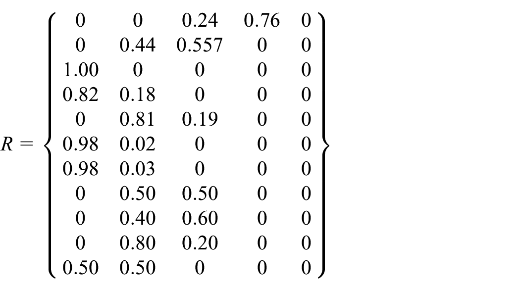
The fuzzy relationship matrix R is established based on the degree of membership calculated using equations (4) to (6) for each evaluation factor with respect to each class.
Fuzzy comprehensive evaluation
The weight set A and the fuzzy relationship matrix R undergo a matrix operation with the weighted average algorithm to obtain the fuzzy comprehensive classification B as follows:
B = (0.2466, 0.3133, 0.2784, 0.16170)
According to the principle of the maximum degree of membership, the maximum value of 0.3133 is taken, the corresponding classification of which is Class II. The comprehensive evaluation results of safety tunnel concrete structure are shown in Table 13.
Comprehensive safety evaluation of tunnel concrete structures.

Results and discussion
The defects in the concrete structures are continuously exposed during the long-term operation of the tunnel, such as concrete lining cracks, separation, and water leakage, which severely affects the operation quality and safety of the tunnel. However, the measurement of these defects is a complicated process, which requires a comprehensive evaluation based on multiple indicators, because relying on any single measurement method will affect the comprehensiveness of the measurement results. In this paper, based on an extensive analysis that takes into consideration the criteria for determining the safety status of concrete structures in highway tunnels and railways, a structural safety comprehensive inspection system and corresponding safety evaluation methods based on fuzzy mathematics for the gas pipeline tunnel concrete structures is proposed. The main conclusions are as follows:
A safety inspection system is established according to the possible defects in concrete structures, which includes the inspection items and corresponding measurement methods. Detect and evaluating the quality of tunnel concrete structures from seven aspects, including the separation behind the concrete lining, the concrete lining strength, the thickness of the protective layer of the reinforced concrete lining, the carbonization depth of the concrete lining, the deformation of the tunnel section, the cracks in the concrete lining, and the auxiliary civil structure of the tunnel. In addition, the quantitative evaluation method and safety classification standard of each inspection item have been determined.
A comprehensive safety evaluation method of concrete tunnel structures is studied based on fuzzy mathematics. A total of 11 indicators, that is, the separation ratio, change in concrete strength, ratio of insufficient protective layer thickness, concrete carbonization depth, tunnel cross-sectional change, longitudinal curvature change, crack width, crack depth, concrete strength, and carbonization depth of tunnel auxiliary civil structures are selected as the main influencing factors to achieve a comprehensive understanding of the quality of the concrete structure of the tunnel from part to whole. In addition, the evaluation results take into account both each indicator and the contribution of each indicator to the overall safety of the structure, and the evaluation results are correlate with the maintenance recommendations.
Based on measurement data from a tunnel of the Nanchang-Shanghai Branch of the Chinese West-East Gas Pipeline, the fuzzy comprehensive evaluation set B is calculated. According to the principle of the maximum degree of membership, the maximum degree of membership at 0.3133 is taken, whose corresponding classification is Class II, indicating that maintenance and minor repair should be carried out after an item-specific inspection.
The comprehensive inspection system, safety evaluation indicators, and quantitative classification standards for concrete structures need to be continuously improved in future engineering practice during the operation of a gas pipeline tunnel for greater reasonableness and feasibility.
Footnotes
Handling Editor: James Baldwin
Declaration of conflicting interests
The author(s) declared no potential conflicts of interest with respect to the research, authorship, and/or publication of this article.
Funding
The author(s) disclosed receipt of the following financial support for the research, authorship, and/or publication of this article: This work was supported by the R&D Projects in Key Areas of Guangdong Province (Grant no. 20191105), the Five Talents Program of IWHR (Grant no. SD0145 B042021), the State Key Laboratory of Simulation and Regulation of Water Cycle in River Basin (Grant no. SKL2020ZY10).
Data availability
The data that support the findings of this study are available from the corresponding author upon reasonable request.