
Abstract
Droplet splitting as a significant feature of droplet-based microfluidic systems has been widely employed in biotechnology, biomedical engineering, tissue engineering, and it has been preferred over continuous flow systems. In the present paper, two-dimensional numerical simulations have been done to examine the asymmetrical droplet splitting process. The two-phase level set method (LSM) has been predicted to analyze the mechanism of droplet formation and droplet splitting in immiscible liquid/liquid two-phase flow in the branched T-junction microchannel. Governing equations on flow field have been discretized and solved using finite element-based COMSOL Multiphysics software (version 5.3a). Obtained numerical results were validated by experimental data reported in the literature which show acceptable agreement. The model was developed to simulate the mechanism of droplet splitting at the branched T-junction microchannel. This study provides a passive technique to asymmetrically split up microdroplets at the downstream T-junctions. The results show that outlet branches’ pressure gradient affects the droplet splitting. Specifically, it has been shown that the splitting ratio increases by increasing the length ratio, and equal droplet splitting can be achieved where the ratio is LL/Lu = 1. We have used two outlet branches having the same width but different lengths to create the required pressure gradient. As the length ratio of the outlet branches increases, the diameter ratio increases as well.
Keywords
Introduction
During the last three decades, rapidly developed micro-total analysis systems (μTAS) have been facilitated a broad range of microfluidic applications in the fields of lab–on–a–chip (LOC), nanomaterials synthesis, biology, chemistry, drug delivery, emulsions, and associated industries. The manipulation of droplets in confined microfluidic devices has been interested in highlighted scientific fields because of the having advantage in the mixing process and transporting. 1 In droplet-based microfluidic (DBMF), a great number of researches can be found which focused on droplet formation and splitting. T-junction microchannels are one of the most typical devices to control droplet formation. In these microchannels, there are usually two immiscible fluids such as water and oil, in which the dispersed phase flows into the main channel from the lateral channel and meets the continuous phase at the perpendicular junction. 2
Droplet splitting is a crucial operation in DBMF, in which droplets broke up into desired sizes for increasing the droplet production efficiency, possibilities of parallel experiments, and enhancing the capacity of up-scaling. 3 The ability to split an original droplet into new droplets is a critical process in microfluidic devices. The new droplets can be used to analyze the samples and as smaller volumes for sample replicates which can scale up the experimental capacity as each droplet behaves as a vessel for reagents. Droplet splitting can be generally classified into two different categories. In the active methods, droplet splitting can be achieved by subjecting a droplet through an additional source, such as electrode, 4 heater, 5 the magnetic field, 6 and pneumatic valve. 7 To break the droplet into multiple smaller droplets, these methods usually require additional components which may increase the complexity of the overall design. Also, the use of thermal and electrical fields may discourage the applications in chemical/bio objects owing to the sustainability of thermal or electrical damage. In contrast, passive droplet splitting is based on a geometry-mediated fission mechanism. The passive method typically relies on some sort of physical microstructures inside a microfluidic channel that obstructs the droplet flow to split the droplet purely based on the force created by the hydrodynamics of the droplet flow. It has been demonstrated that droplet splitting can be obtained steadily at precise locations such as T-shape junction, 8 three-dimensional (3D) crossing microstructure, 9 artificial obstacle inside the channel, 10 and branching channels. 11 Interest in the numerical modeling of flow and transport phenomena has enhanced in recent years along with the rapid increase in computational power. However, efficient numerical algorithms, new mathematical formulations, and advanced computational techniques are needed if researchers are to take full advantage of this progress and address new and existing challenges in transport modeling and simulation.12–14 Several studies have been experimentally and numerically investigated to find the effects of various factors on the droplet formation process.
Thorsen et al. 15 firstly considered the droplet formation within a T-junction microchannel. They demonstrated a novel microfluidic system that can generate complex, ordered patterns of microdroplets. The flow regime in this microfluidic device is commonly simple – viscous effects dominate and laminar flow due to the low Reynolds number. Self-assembly of the vesicles into a template depends on several parameters such as type of geometry and pressures. Sivasamy et al. 16 found that the pressure profile of the dispersed phase and the continuous phase in the squeezing regime change as the droplet breakup process proceeds. In the droplet splitting process, new approaches are taken on the pressure difference between the dispersed phase and the continuous phase and illustrated that lower pressure difference occurs at the last time of the droplet splitting. Nisisako et al. 17 provided a novel approach for generating water-in-oil droplets, with oil as the continuous phase and water as the dispersed phase, in a microchannel network. Hence, the droplet size can be controlled in this microfabricated device, the minimum diameter of the droplets was about 100 µm, and the maximum 380 µm, as the flow velocity of oil was changed from 0.01 to 0.15 m/s2. Garstecki et al. 18 established a simple scaling law for the length of the droplet that is independent of the capillary number and merely related with the flow rate ratio of the two immiscible fluids.
Chen et al. 19 proposed a 3D simulation using the Volume-Of-Fluid (VOF) method to disclose the mechanism of microdroplets breakup in a T-junction bifurcation. They numerically and experimentally observed four different microdroplet flow regimes (break up with permanent obstruction, break up with discontinuous obstruction, break up with the tunnel, and non-breakup). They showed that the breakup and non-breakup of droplets can be controlled by the parent droplet length and the Capillary number. Chen and Deng 20 developed a phase-field multiphase lattice Boltzmann model to investigate the dynamic behavior of a microdroplet passing through a microfluidic T-junction. They found that the tunnel’s appearance (the lubricating film between channel walls and droplet) slows down the droplet deformation rate and provides a precondition for the non-breakup of droplets. Additionally, they showed that when the strength of vortex flow formed inside droplets exceeds a critical value, the droplet does not break up. Their results also reveal that a large droplet viscosity restricts vortex generation. Consequently, the breakup of a droplet with larger viscosity is easier. Cheng et al. 21 numerically examined the droplet splitting process in an asymmetric T-junction bifurcation with different pressure gradient ratios. They observed four modes of droplet breakup (transition-, bubble-, primary-, and non-breakups). They showed that the asymmetric breakup splitting ratio depends on the dwell time of the droplet at the junction before breakup and flow conditions. Fu et al. 22 numerically and theoretically investigated asymmetric droplet breakup under a pressure difference at two outlets of a T-junction using the lattice Boltzmann method based on the color gradient model. Their results show that asymmetric breakup follows two steps, namely, the filling stage and the breakup stage. Also, they proposed a universal parameter to describe the asymmetric breakup condition in the T-junction. They showed that this parameter has the main role in characterizing the droplet length of formed smaller droplets and the temporal evolution of volume ratio. He et al. 23 studied the transient breakup behavior of slug flow units at a T-junction microchannel using the VOF method. They studied the effects of the characteristics of slug flow units including the surface tension, the capillary number, and the length/length ratio of the gas bubble to the liquid slug on the split of gas bubbles and liquid slugs. Samie et al. 24 proposed asymmetricT-junctions with branches of identical lengths and different cross-sections for generating unequal-sized microdroplets. They developed an equation for determining the breakup point of droplets and one for the critical droplet breakup at asymmetric T-junctions. Shen et al. 25 designed two different microstructures to achieve droplet merging and splitting respectively. They quantitatively compared different flow dynamics in different microstructures for droplet merging and splitting via micro-particle image velocimetry (micro-PIV) experiments. They observed some new droplet flow phenomena different from previous researches. They also found that the Y-junction bifurcation can split droplets more effectively than a cylinder obstacle. Moreover, they showed that the velocity vector fields of droplets have a significant influence on the droplets merging and splitting. Wang et al. 26 experimentally and theoretically studied droplet breakup in an asymmetric bifurcation with two angled branches. They examined the effects of the parameters such as the droplet velocity and initial droplet length on breakup characteristics. The results of their research show that these parameters have a large influence on the splitting ratio, which proves that the breakup process is an interdependent process between the splitting junction and droplets themselves.
According to the above discussions, considerable research has been devoted to investigating the droplet splitting process in T-shape bifurcations. Only a little attention has been paid to the numerical study on droplet splitting in a junction having different pressure gradients. Asymmetrically droplet splitting has attracted increasing interest in the last decades, due to its crucial applications in LOC. Current research provides a passive technique for asymmetrically microdroplet splitting at a T-junction microchannel. This can be passively adjusted through the pressure gradient using the unequal branch outlet lengths. Governing equations on flow field have been discretized and solved using finite element-based COMSOL Multiphysics (version 5.3a) software. Obtained numerical results were validated with the experimental data reported in the literature. The two-phase flow in the T-shape bifurcation and splitting mechanism were analyzed and governing dynamics of the unequal-size microdroplet production were investigated. This paper will be of high value in designing microchannels to examine different droplet splitting ratios, as different biological applications require wide ranges of different original droplet sizes, splitting ratios, and new droplet sizes.
Calculation model
Geometry
A branched T-junction microchannel was created to generate and split micro-sized droplets (see Figure 1). Figure 1 demonstrates the studied channel geometry in this paper which contains a horizontal main channel, aside perpendicular channel, and two outlet branches. The continuous phase flows along the main channel whereas the dispersed phase flows through the narrow side channel as shown in Figure 2. After a droplet is generated, it moves toward the outlets and breaks up into two smaller droplets at the outlet bifurcation.

The geometry used in the current simulation for droplet splitting at a branched T-junction.
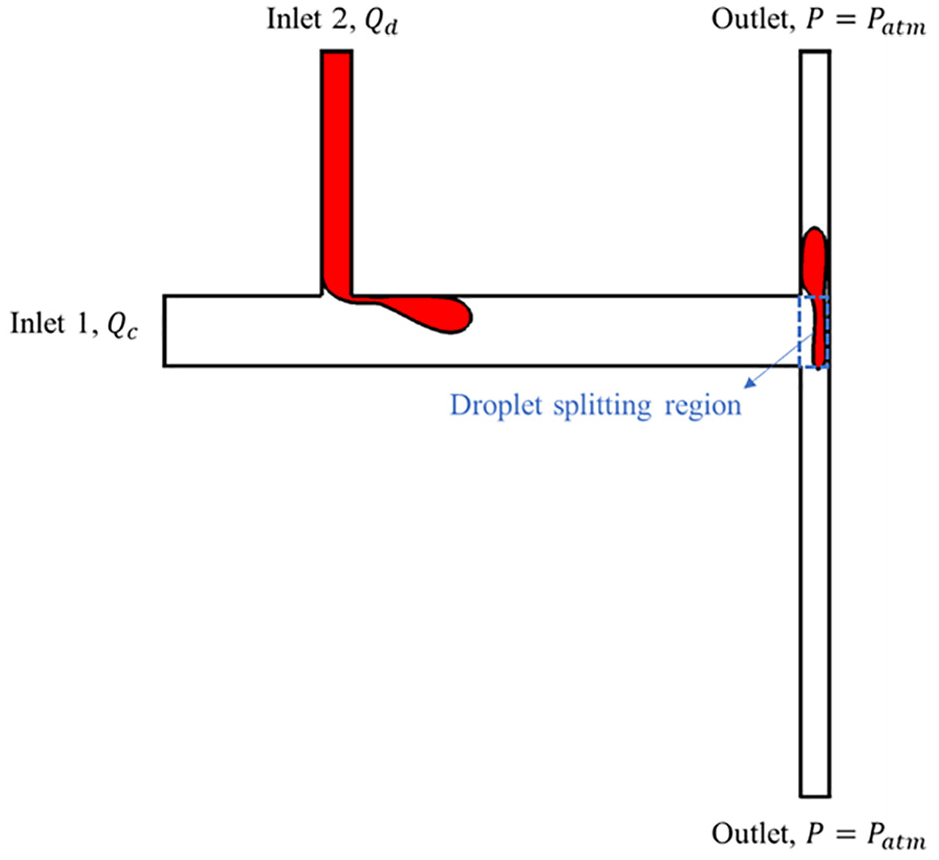
A schematic view of the inlet and outlet conditions and droplet splitting region.
Governing equations
Fluid flows in microchannels are usually laminar due to the low Reynolds number. Thus, the continuity equation, incompressible Navier–Stokes equations, and Level Set equation can be used to describe such fluid flows.
The Level Set Method (LSM) is a technique to represent moving interfaces or boundaries using a fixed mesh. The LSM is useful for problems where the computational domain can be divided into two domains separated by an interface. The interface between two immiscible fluids is defined by the 0.5 contours of the level set (phase) function (
Continuity equation:

Incompressible Navier-Stokes equation:

Level-Set equation:

Where

where
The interfacial curvature:

The delta function:

The density and the viscosity of the two phases can be calculated using equations (7) and (8) at any point of the domain.


In this work, the droplet effective diameter (d) is the main output parameter. To obtain the droplet effective diameter an area integration of the volume fraction of the dispersed phase (where ϕ > 0.5) is performed, and it can be calculated using equation (9). 29

The flow rate ratio is given as

Boundary conditions
At the inlets, the “laminar inflow” boundary conditions with prescribed volume flow rates are defined. The “no viscous stress” boundary condition is applied at the channel outlet. All other boundaries are considered as the “wetted wall” with the contact angle of 180° and a slip length being equal to the mesh element size. The contact angle (wetting angle) is the angle between the surface of the liquid and the solid surface at the points where the liquid attaches to the solid surface. The slip length defines as an extrapolated distance relative to the position outside the solid surface where the tangential velocity component becomes zero.
Fluids properties
Water and olive oil have been chosen as working fluids in this study. Water is the dispersed phase and olive oil is the continuous phase. Physical properties of water and olive oil are gathered in Table 1. 1
Physical properties. 1

Mesh independence study
A structured two-dimensional mapped mesh has been generated to discretize the planar geometry of the microchannel in this work. In Figure 3, the grid profile of the T-junction microchannel is illustrated. Before the numerical study, the mesh independence study was performed to quantify the dependency of simulation results on mesh size. In the regions near the dispersed phase where flow gradients exist and therefore mesh elements sizes are refined to capture the most detailed information. Table 2 summarized the mesh convergence test for the dependence of droplet effective diameter on the number of mesh elements when the flow rate ratio (

Geometrical discretization of the microchannel.
Effect of number of mesh elements on the droplet effective diameter.


The velocity profile at the cross-section after the original droplet for three elements numbers.
Numerical model validation
To validate the model, a two-dimensional numerical model is calculated against a matching laboratory experiment which was done by Wong et al. 1 To compare our results to literature data, geometry and the properties of the fluids are set up the same as theirs. The droplet effective diameter is compared to the results which were obtained by Wong et al. 1 Figure 5 illustrates the comparison of the droplet effective diameter as a function of the applied flow rate ratio, Q, between the numerical simulation results of current work and experimental results. 1 The difference between the simulation data and the experimental data is roughly 7% at the flow rates ratio of 0.125 and for other flow rates, there is a reasonably good agreement (see Table 3). The error values lower than 9% were a good agreement while comparing the experimental results with the values obtained numerically for similar clearance values. 30 Results in Figure 3 show that the droplet effective diameter gradually increases with the rising flow rate ratio.
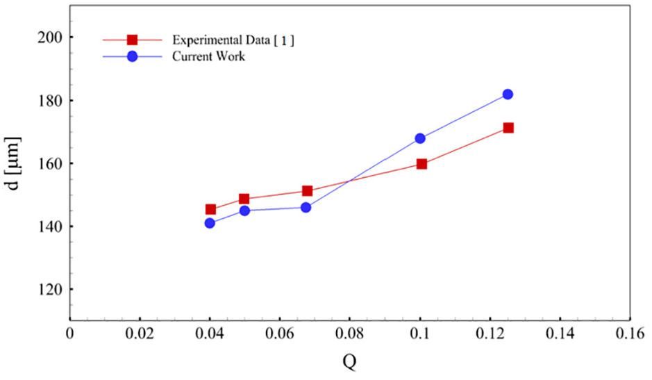
Comparison of droplet effective diameter as a function of the applied flow rate ratio.
Numerical simulation error versus experimental data for various flow rate ratio values.

Results and discussions
This section aims to examine the droplet splitting process inside a branched T-junction using a passive method. In this process, an original droplet breaks up into two smaller droplets (namely new droplets) due to the flow conditions and geometry of the channel. Figure 6 shows the schematic of this process. Outlet branches with different lengths have been used in current work to asymmetrically split the original droplet. The droplet splitting process commences by arriving at the original droplet to the bifurcation. If the original droplet diameter is bigger than the branch width, pressure buildup will appear at the flow upstream. This pressure buildup acts like a required droplet splitting initial force which overcomes the surface tension. The built-up pressure pulls the original droplet into the outlet branches and a dumbbell-shaped droplet forms. This mechanism continues until the original droplet length inside the branches (
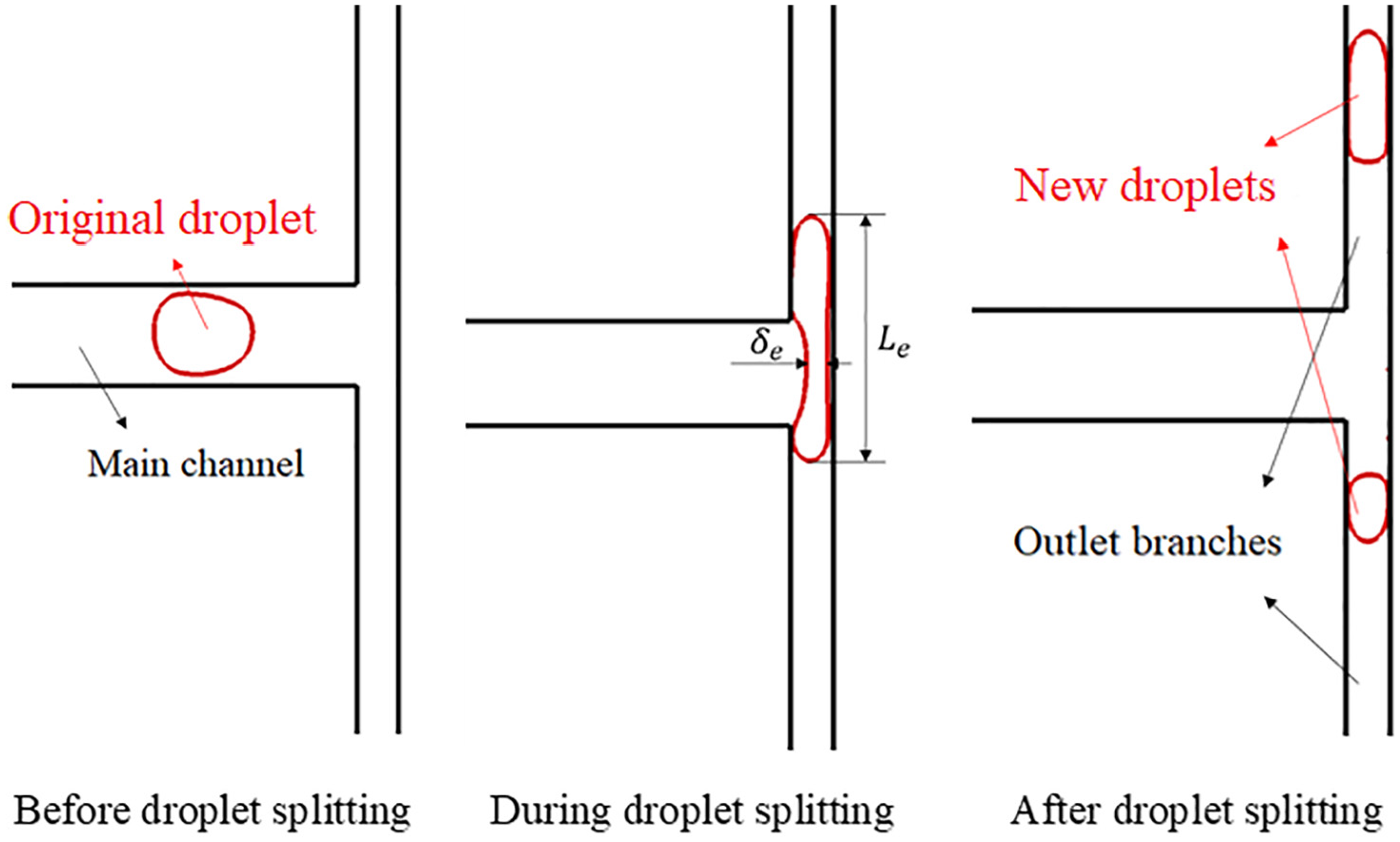
Schematic of droplet splitting process.
Droplet splitting dynamic
Generally, the surface tension of the droplet and the upstream pressure buildup are correspondingly regarded as the main resistance force and the driving in a droplet splitting through a T-shape microchannel.31,32 Figure 7 demonstrates the pressure contours during the splitting process. As shown in Figure 5 when the original droplet completely occupies the splitting region, upstream flow pressure effectively increases (t = 0.08 s). For better understanding, quantitative graphs of pressure distribution along the main channel centerline (where the droplet splitting process starts) are illustrated in Figure 8. By moving the droplet through the main channel, upstream flow pressure along the centerline remains constant (Figure 8(a) and (b)). When the original droplet arrives in the branching region, it blocks the flow of the continuous phase flow. This causes the upstream pressure build-up, thus, the pressure of the upstream flow increases (Figure 8(c) and (d)). In Figure 6 slope of the pressure graphs are almost the same but in Figure 8(c) and (d) pressure of the starting point on the centerline is higher in value in comparison to the one in Figure 8(a) and (b) because of what discussed above.

Evolution of pressure contour for symmetric droplet splitting.

Pressure profile together with
Finally, it should be mentioned that if the droplet diameter is being smaller than the channel width, the small original droplet fails in creating the needed pressure build-up for splitting and the original droplet flows into only one of the branches depending on the flow conditions.
Pressure gradient effects on droplet splitting
The size of the broken-up droplets depends on the pressure gradient of the two outlet branches. Considering the length of one of the outlet branches larger than the other one leads to a pressure gradient in the two outlets. This pressure gradient is the required force to asymmetrically break the original droplet into two droplets of varying sizes. Enlarging the lower branch length to the upper branch increases the velocity in the upper branch and causes stronger vortex generation at the entrance area. This can be justified by the Darcy-Weisbach equation. Equation (11) gives the relation of the pressure gradient created in each outlet by changing the length of the lower outlet. 33

Where

According to equation (12), it is clear that as the length ratio increases, more fluid flow directs to the upper branch than to the lower branch. Figures 9 and 10 show the streamlines and schematic of the vortex formation for the two different cases (length ratio equal to one and greater than one). Figure 9 shows the parallel velocity streamlines due to the original droplet has not been reached the splitting junction. According to Figures 9 and 10, in symmetrical droplet splitting (

Streamlines in a symmetric and asymmetric droplet splitting.

Generated vortices in a symmetric and asymmetric droplet splitting.
Capillary force effects on droplet splitting
The physical mechanism of the capillary forces has an effect on the dynamic of drop spreading was investigated by Lugscheider et al. 34 Fedorchenko and Wang 35 proposed the mathematical model for the drop spreading, accounting for the blob generation on the edge of spreading drop. During the droplet splitting process a pointed end forms behind each new droplet. The droplets edge involves a moving contact line, which is the intersection of a liquid phase and a solid surface. In the vicinity of the droplet edge, the capillary forces have significant effects. Since the shape of the droplets is far from that in equilibrium, capillary forces try to deform the leading edge of the drop forming the blob. Under the action of capillary force Fσ = σ(1−cosθ), where θ is the dynamic contact angle, the blob moves toward the spreading drop, absorbing the mass and momentum of the wall sheet. When the speed of the blob relative to the liquid becomes equal to the velocity of the liquid in the sheet, the blob comes to a stop. Rapid formation of the pointed interface cause in generating strong capillary force. This force pulls the pointed interface toward the droplet center and the droplet gradually moves into the shape of a circle-like and pointed end disappears after a little time passing. This has been shown in Figure 11.

Capillary forces acting on the new droplets.
Length ratio
As mentioned above, the splitting mechanism could be highly affected when the channel height is modified and detached new droplets’ size depends on outlet branches’ pressure gradient. In the current work, this gradient has been provided by considering the lower branch length longer than the upper one. Length ratio is defined as,

Variation of splitting ratio with length ratio.
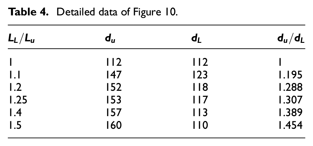
Detailed data of Figure 10.

Symmetric droplet splitting evolution

Asymmetric droplet splitting evolution
Velocity distribution
To better understand the splitting process in the T-junction microchannel, velocity is the main parameter that must be studied. In Figure 15, velocity distribution for length ratio of 1.5 are shown at three various times, t = 0.085, 0.090, and 0.095s. Three different times are selected, before the droplet splitting, at the moment of the droplet breaking up and after the splitting the original droplet which is obvious in Figure 15. The highest velocity is observed in an upper branch which has a high volume ratio. It can be concluded from the above-mentioned results as the length ratio of the outlet branches increases; a larger portion of the original droplet is pulled through the upper branch. Figure 16 illustrates the vorticity contours in the asymmetrical droplet splitting process in the length ratio of 1.5. The strength of the circulating flow formed within the droplet changes after it is split up. The size of the circulating flow inside the larger new droplet is greater in comparison to the smaller new droplet. This may be because of the presence of the larger vortex at the point of entry into the shorter branch. The vortices created within the original droplet are enlarged by combining the vortices formed at the inlet of the outlet branch, and the stronger circulating flow occurs inside the larger new droplet. For better understanding, velocity profiles for various length ratios (
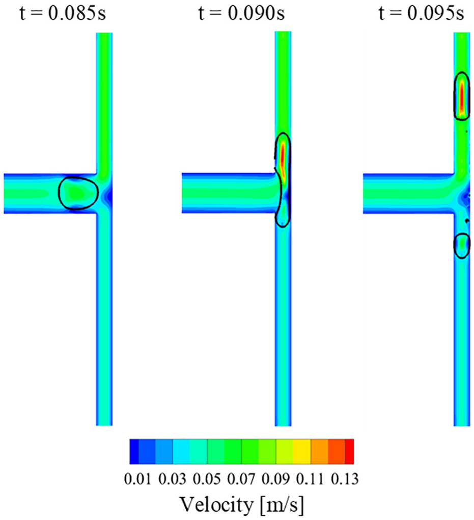
Velocity contours.
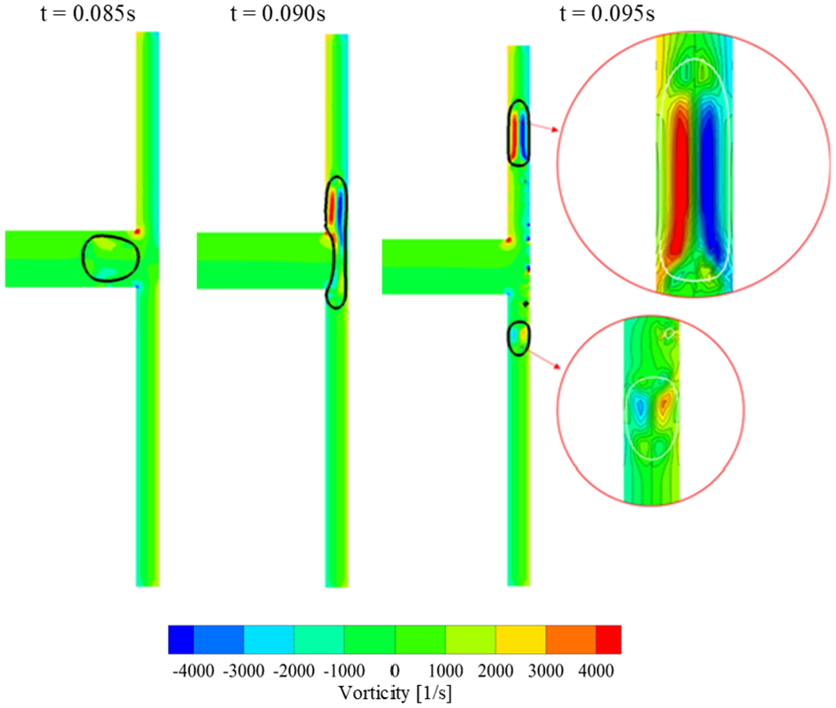
Vorticity contours.
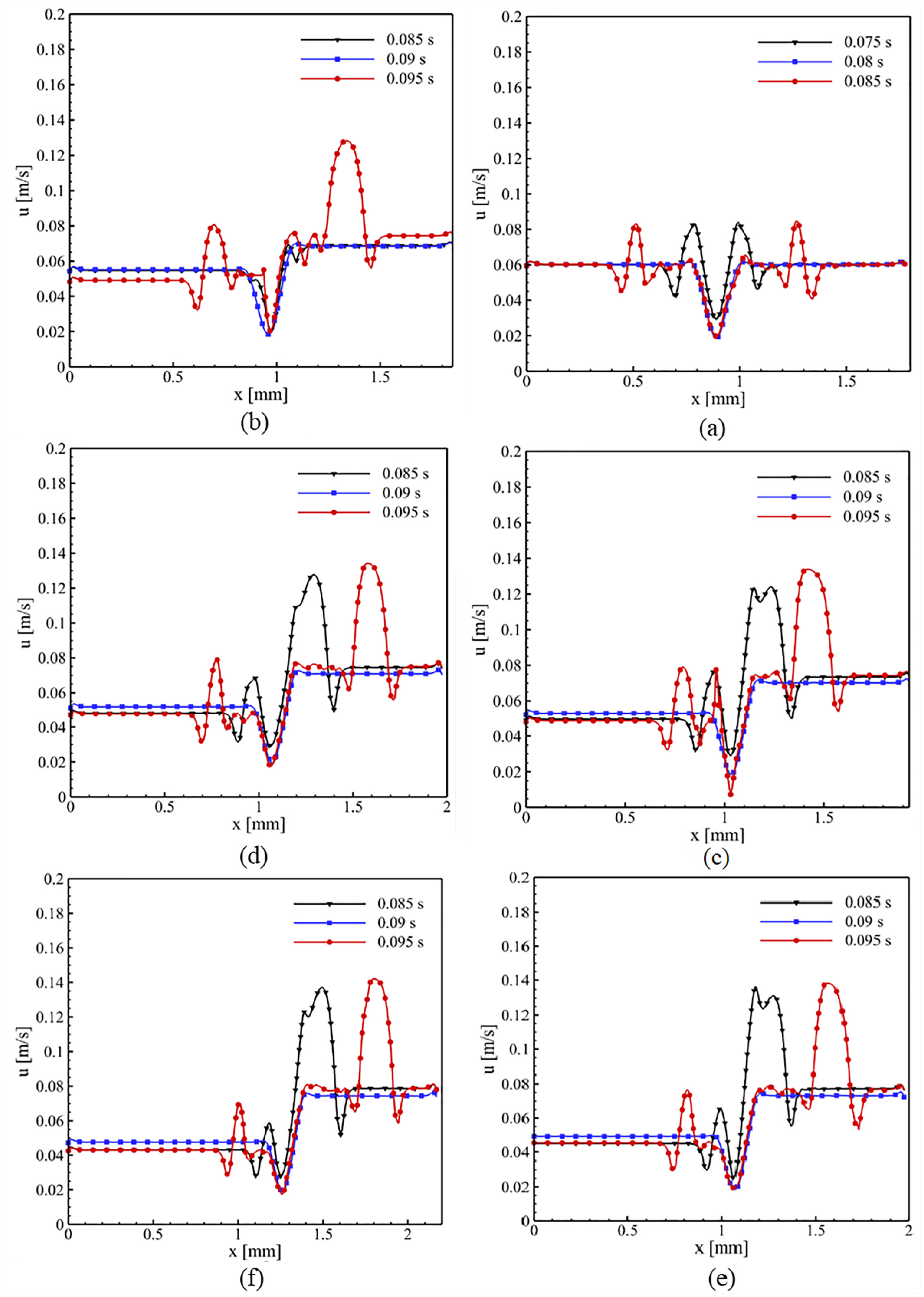
Velocity profile at the outlet branches for various length ratios (
Conclusions
The numerical simulation of the liquid-liquid two-phase droplet flow in branched T-junction microchannel was investigated using Level Set Method (LSM) with COMSOL Multiphysics software (version 5.3a). The droplet splitting was studied in the continuous oil phase and splitting of the droplets at T-junction having various length branches. The model used in this simulation was validated by comparing the investigated data from the simulation with the experimental results reported in the literature. Then, the model was developed to simulate the dynamics of the asymmetric droplet splitting process at T-shaped bifurcation as an innovation of current work. Further simulations were performed to study the flow conditions and pressure force for the asymmetric breaking of droplets. Some obtained key results in the present study can be listed as follows:
At the moment the original droplet arrives at the branching region, it blocks the main channel consequently the upstream pressure build-up and pressure of the upstream flow increases.
The droplet becomes thicker as the length of the lower branch increases, the diameter of the droplet is enhanced in the upper branch. The maximum splitting ratio (
It is observed that the velocity increases in the upper branch as the length ratio (
It is observed that using two outlet branches having the same width and different lengths causes asymmetric droplet splitting.
Footnotes
Appendix
Handling Editor: Andreas Rosenkranz
Declaration of conflicting interests
The author(s) declared no potential conflicts of interest with respect to the research, authorship, and/or publication of this article.
Funding
The author(s) received no financial support for the research, authorship, and/or publication of this article.