
Abstract
In this work, we designed a particle damper which can be conveniently clamped on to a pipeline without affecting the existing structure, showing a promising application in vibration reduction of real aircraft. Based on the designed particle damper, the impact of particle filling rate on the vibration reduction effect, the effect of EDEM simulation on the energy consumption of particles in the vibration process of the damper, and the result of actual vibration reduction test of particle damper installed on hydraulic pipeline were investigated. It is found that the vibration of the pipeline decreases first and then increases with the increase of particle filling rate. The particle filling rate corresponding to the maximum particle energy consumption rate is consistent with that of the minimum pipeline vibration acceleration during the test, that is, from 94.9% to 97.9%. The simulation results are in good agreement with the test results. Moreover, the vibration of the hydraulic pipeline and actual aircraft pipeline are both obviously suppressed after the installation of the particle damper. These results fully demonstrate the effectiveness and practicability of the aircraft pipeline particle damper.
Introduction
The pipeline structure plays an important role in the aircraft hydraulic system, which undertakes the critical tasks of the transportation of fuel, lubricant, air, and hydraulic fluid to all parts of the aircraft. According to the working conditions of the pipeline, the main forms of failure include fatigue damage, wear, and burst leakage caused by vibration. To our best knowledge, the vibration mainly comes from the vibration of the engine, the pressure pulsation of the fluid, and the impact pressure of the pipeline. As per the research findings, 1 pressure pulsations account for more than 90% of vibration failures in the actual work conditions of aircraft hydraulic pipeline, and the exciting force is found to increase with the increase of the unevenness of the pressure pulsation. The normal operation of the aircraft hydraulic pipeline is directly related to the flight safety, therefore, it is urgent to develop an effective method to control the pipeline vibration, thereby preventing the flight accidents caused by the pipeline failure.
Passive control methods are widely used and accepted in pipeline vibration control, such as clamps, improvement of the rigidity of pipeline system, change of the natural frequency, and elimination of low-frequency resonance.2–9
However, in many cases, the structure limitations prevent the application of the pipe clamps. It is worth noting that the pipeline damper has little dependence on the surrounding environment, which is available for vibration reduction by being installed on the pipeline only. In this case, there is great demand to investigate the pipeline damper. Chiba and Kobayashi 10 summarized the dampers commonly used in piping systems, including electro rheological dampers, viscoelastic dampers (VED), and elastoplastic dampers (EPD). All these dampers are able to lower the fluid pulsating pressure and suppress pipeline vibration effectively. Yang et al. 11 invented a liquid pipeline damper, and Chen et al. 12 proposed a dynamic vibration absorber applicable for vibration reduction of pipe system. Based on Chen’s research, Zhou et al. 13 designed a frequency-adjustable dynamic vibration absorber which could reduce the vibration of the pipeline at different resonance frequencies effectively.
In the past years, a series of methods for the reduction of system vibration by using dissipating system energy were proposed, including particle impact damper technique, 14 metal-rubber composite absorber technique, 15 friction damper technique, 16 fluid viscous damper technique, 17 etc. Among them, the particle damping technique is characterized by the advantages of low cost and easy implementation, especially suitable for the utilization in harsh environments. With the continuous relevant research, particle damping technique has been successfully applied in aerospace and mechanical fields. For example, Panossion 18 greatly reduced the high-frequency vibration (4000 Hz) of the liquid oxygen inlet blade by using particle damping technique. Xu et al.19,20 applied particle damper to beam structure and plate structure, and found that the technique exhibits good effect under the vibration above 1500 Hz, but with poor effect for low-frequency vibration. In theoretical research, Cundall 21 proposed the discrete element method which simulates the interaction force between particles by establishing different contact models, following by the simulation of the motion characteristics of particles. The particle flow calculation software EDEM (event-driven discrete element method) was developed by DEM – Solutions Inc. based on discrete element method, which is widely used to simulate and analyze particle movement operations. Lu22–26 established a mechanical calculation model for inter-particle collisions. Though the above studies have developed the particle damping technology to some extent, in the previous research work, particle damping techniques were mainly used for the vibration reduction of blade structure, beam structure, and plate structure. The objective of this research lies in the perforated design of honeycomb structure, and the particles were loaded into small holes or honeycomb cavities to form a composite structure, thus achieving the effect of vibration reduction. There are no reports on vibration reduction of pipeline structure and practical engineering application, especially the research of the control of the vibration of pipeline system via externally attached particle dampers.
This paper proposed an aircraft pipeline damper based on particle damping technique of which the effectiveness and practicability have been proved by simulation and experiment. The novelty of the work mainly lies in the application of this technology to aircraft pipeline vibration reduction. We discussed the design of the damper and its vibration damping mechanism. Besides, we considered the influencing factors of vibration reduction and the optimization of design parameters, etc., which are different from the previous efforts.
Design of particle damper
The particle damper designed in this paper uses lightweight aluminum alloy to avoid the problem of large stress due to the excessive mass of shock absorber. At the same time, considering the assembly space and energy consumption efficiency, a container with curved inner wall was selected. Firstly, the circular section needs less space than the square section, which endows the former more convenience for installation. Secondly, in contrast with the regular movement of particles in a container with flat inner wall (Figure 1(a)), the movement of particles in the containers with curved inner walls are chaotic and irregular (Figure 1(b)). The irregular movements of particles are usually accompanied by (a) frequent collisions with the flat inner wall and higher friction between particles and the inner wall of the container, leading to higher energy consumption.
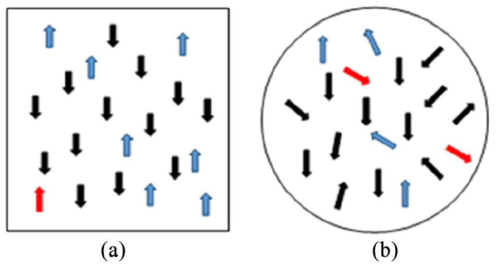
Particles movement state in closed structure: (a) flat inner wall and (b) curved inner wall.
The instrument employed in this work is obtained by the addition of a particle damper with the diameter of 50 mm and the thickness of 3 mm to a pipe with the diameter of 21 mm. To ensure a good sealing effect of the damper, both sides of the cavity are sealed with cover plates in the thickness of 1 mm, and a bolt with the diameter of 1.4 mm is used to fasten the cover plates of the cavity through six pre-manufactured bolt holes on both sides. In addition, the grooves in the width of 10 mm and the depth of 6 mm are prepared on the half and lower semicircular cavities, and through-holes with the diameter of 4 mm were opened in the aluminum alloy plane inside the groove. The two cavities can be tightly clamped onto the pipe by installing bolts with the diameter of 4 mm in the through-holes. The schematic and physical particle dampers are shown in Figure 2(a) and (b), respectively. Considering the influence of the cavity structure on the damping effect of the damper, thin iron sheets are used to divide the inside of the each semicircular cavity into three small chambers, as shown in Figure 2(c). The maximum outer diameter of the cavity is 50 mm, and the thickness of the wall between the three small chambers basically evenly distributed is 3 mm, as shown in Figure 2(c). The holes are divided into six holes in the inner ring, which are of Size M4 and used to install the damper onto the pipe. In addition, there are six holes in the outer ring, which are of Size M1.4, and utilized to cover the plate so that the particles are enclosed in the damper.

Particle dampers: (a) model, (b) single unit, and (c) multi unit.
Simulation of particle collision energy consumption
Energy consumption mechanism of particle collision
Particle collision damping technology is developed to consume the vibration energy of the system through the impact and friction among particles, thus achieving the purpose of vibration reduction. For multi-particle systems, the discrete element method (DEM) is usually needed, which calculates the interaction among particles, judges the real-time position of the particles, and iterates the contact force and displacement of the particles to analyze the collision energy consumption mechanism of the entire system. The cycle calculation process of the DEM is shown in Figure 3.

Cycle calculation process.
Based on the force-displacement relationship, the force of the particle can be understood through the displacement. And according to Newton’s second law, the motion equation of particle i can be obtained by using equation (1):
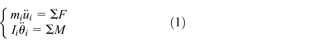
where
Then use the central difference method to solve equation (1), as shown in equation (2):

where
Integrating equation (2), the equation (3) can be obtained:

Then use Euler’s method to solve equation (3), the update speed of the next time step is shown in equation (4):

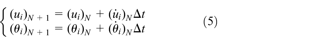
Finally, integrating both sides of equation (4) to obtain equation (5):
The discrete element method to describe the process of particle collision is actually used to describe the process of contact generation and effect. In the process of particle collision analysis, different contact models should be established for different simulation objects, therefore, it is very important to select the appropriate contact model. In this paper, the Hertz-Mindlin (no slip) contact model is mainly used for the simulation and analysis of the motion state between particles.
Suppose the radii of the two particles are R1 and R2, respectively, and the velocities before the collision are v1 and v2. The normal force Fn and the normal damping force

where

In addition, the coefficient


where r1 and r2 refer to the center position vectors of the sphere particles, n represents the normal unit vector, and e denotes the coefficient of restitution.
Furthermore, the tangential force

where

In addition, the rolling friction of the spherical particles during the simulation can be explained by the moment M on the contact surface, as shown in equation (12):

To analyze the particle system, it is basically assumed by the discrete element method that the force and acceleration experienced by the particle are constant within a time step. If the time step selected is too large, it may lead to the numerical calculation to diverge, therefore, the description of the inter-particle contact is not accurate, and even the collision detection may be missed. On the contrary, in the case of too small time step, it may greatly increase the amount of calculation. Therefore, it is important to choose an appropriate time step for the simulation calculation and analysis of the particle collision system.
The single degree of freedom system can be utilized to calculate the iterative time step Δt of the discrete element method with its motion equation shown in equation (13):

The acceleration can be obtained based on the principle of central difference, as shown in equation (14):

Substituting equation (14) into equation (13), equation (15) can be obtain as follows:

Then we can get equation (16):

Because u(t) shows the vibration characteristics of reciprocating motion, the solution is a complex number. Therefore, it should be satisfied with equation (17):

So we can get equation (18):
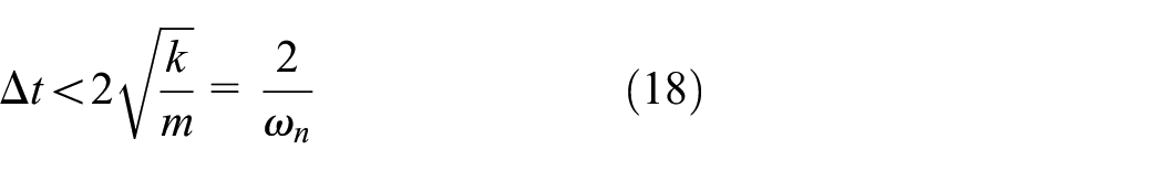
Due to the natural frequency of the system

In the system, the minimum natural vibration period of each unit is less than that of the system itself. Therefore, the calculation condition of Δt should be equation (20):
Among them,

In the case that the system is an under-damped system, Δt should be calculated by using the central difference method, as shown in equation (22):

When the maximum value
Particle collision damping technology is mainly based on the energy consumption of elastic collision and frictions of particles. Therefore, taking two-particle system for example, the energy consumption during elastic collision can be calculated according to equation (23):

where
The friction energy consumption is calculated by using equation (24):

where
EDEM modeling and simulation parameter settings
The particle flow calculation software EDEM is employed for the simulation and analysis of the particle energy consumption of the designed particle damper. The simulation process is mainly divided into three parts, that is, modeling, dynamic simulation, analysis and post-processing.
Firstly, the finite element is utilized for the modeling of the particle damper with the model shown in Figure 4. Table 1 27 lists the parameter setting of the finite element simulation which mainly includes the contact parameters, the properties of structure, and the materials of particles. Among them, the materials of damper and particles are aluminum alloy and cast iron, respectively. The contact parameters mainly refer to the relevant parameters of aluminum alloy-cast iron and cast iron-cast iron. The Hertz-Mindl in (no slip) the model is selected as the contact model due to that fact that its energy consumption mainly consists of elastic collision and rolling friction. Subsequently, the dynamic simulation is performed. The excitation type is single-direction sinusoidal excitation with the vibration displacement amplitude of 1 mm, the vibration frequency of 400 Hz, the time step of 40% of the Rayleigh time step, and the grid size of three times of the minimum radius of the particles.
The model of particle damper.
Simulation parameters.

Effect of filling rate in cavity on particle energy consumption
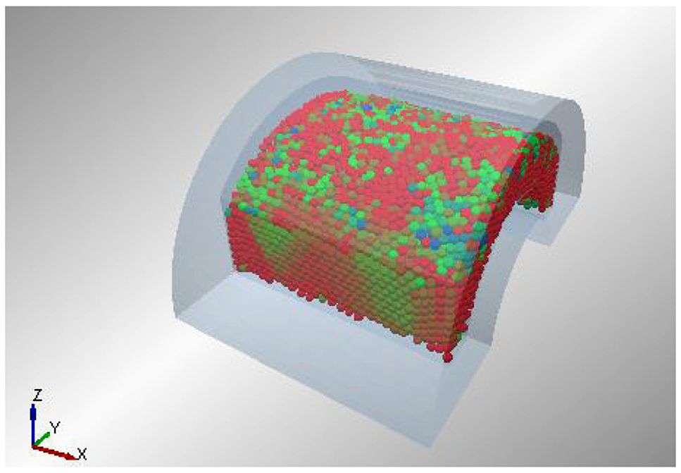
For the finite element model established by EDEM, during the simulation process, particles are continuously put into the container until no more particles can be added. In this state, the number of particles in the container corresponds to a filling rate of 100%. In addition, the vibration of particles at different filling rates can be calculated by changing the number of particles filled into the container. To investigate the effect of filling rate inside the cavity on energy consumption, the excitation type is set as single-direction sinusoidal excitation with the vibration displacement amplitude of 1 mm, the vibration frequency of 400 Hz, and the total calculation time of each segment for particles with a diameter of 1, 2, and 3 mm are set to 0.1, 1, and 1 s, respectively.
The results of simulation calculation are shown in Figure 5(a) to (c) of which the left side shows the change in the particle number with different sizes ((a) 1, (b) 2, (c) 3 mm) over time, and the right side shows the change in the total energy consumption in the corresponding container over time.

The simulation calculation results: (a) 1 mm, (b) 2 mm, and (c) 3 mm.
The optimal filling rate is determined by the calculation of the energy consumption rate at different particle filling rates. As shown in Figure 6, when the filling rate is lower than 50%, the energy consumption rate varies less. While when the filling rate falls into the range of 50%–70%, the energy consumption rate displays an obvious upward trend. After the filling rate reaches to 70%, the energy consumption rate shows a steady increase until reaching the optimal value, and then decreases. In fact, when the filling rate reaches a certain critical value, the gap between the particles is extremely small, and the collision and friction between particles become limited, which leads to the reduced energy consumption efficiency. It is worth noting that in the simulation process, due to the non-negligible effect of the manually set vibration displacement on the judgment of the optimal energy-consuming filling rate, the particles with different sizes display different optimal energy consumption filling rate. When the vibration displacement amplitude reaches 1 mm, the optimal filling rate corresponding to the particles size of 1, 2, and 3 mm is 85%–100%, 75%–97%, and 90%–100%, respectively.
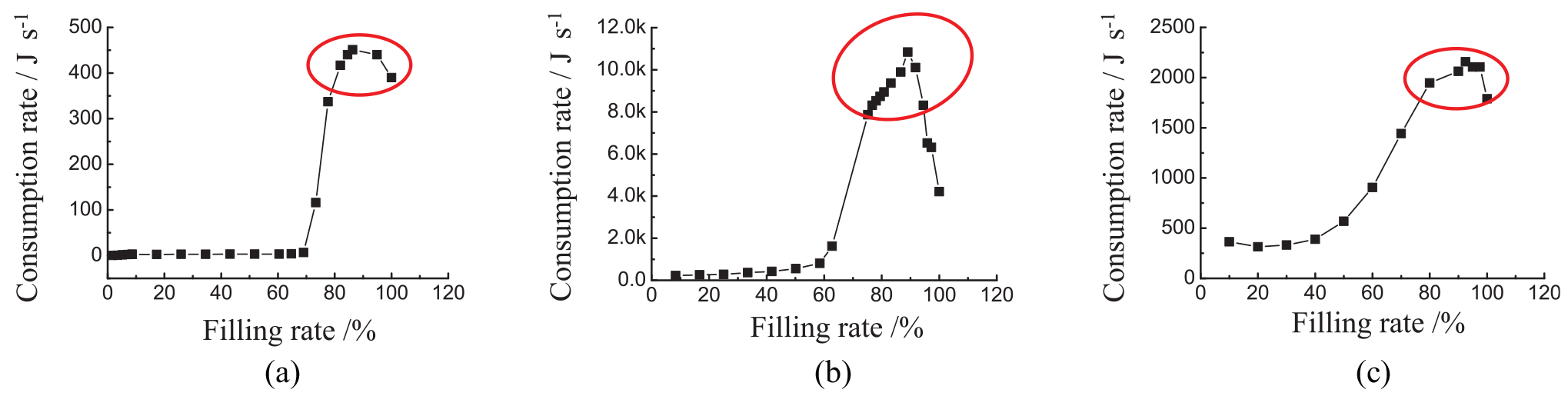
The energy consumption rate at different particle filling rates: (a) 1 mm, (b) 2 mm, and (c) 3 mm.
Effect of vibration displacement on particle energy consumption
Taking the particles with the diameter of 3 mm for example, the main structure of the damper is used as the moving space of the particles. And the effects of vibration displacement on energy consumption are compared by changing the displacement amplitude which is set as 1, 2–10 mm (interval of 2 mm), and the filling rate is set as 30%, 50%–100% (interval of 5%), respectively. EDEM software is selected as the simulation tool with the simulation time for each group of 0.1 s.
The influence of the vibration displacement on the optimal filling rate can be obtained according to the simulation data with the results shown in Figure 7. Figure 7(a) reveals the relation between the energy consumption rate and the filling rate. It can be seen from Figure 7(a) that, (i) Under different vibration displacements, the energy consumption rate of particles increases first and then decreases with the increase of particle filling rate. (ii) At the same filling rate, the larger the vibration displacement, the higher the energy consumption rate. (iii) The particles with smaller vibration displacement need much higher filling rate to reach the maximum energy consumption rate. The red line in Figure 7(a) exhibits this rule. Figure 7(b) illustrates the optimal fill rate, and the energy consumption rate change with vibration displacement. As shown in Figure 7(b), with the increase of the vibration displacement, the optimal filling rate of particles decreases, while the maximum energy consumption rate increases.
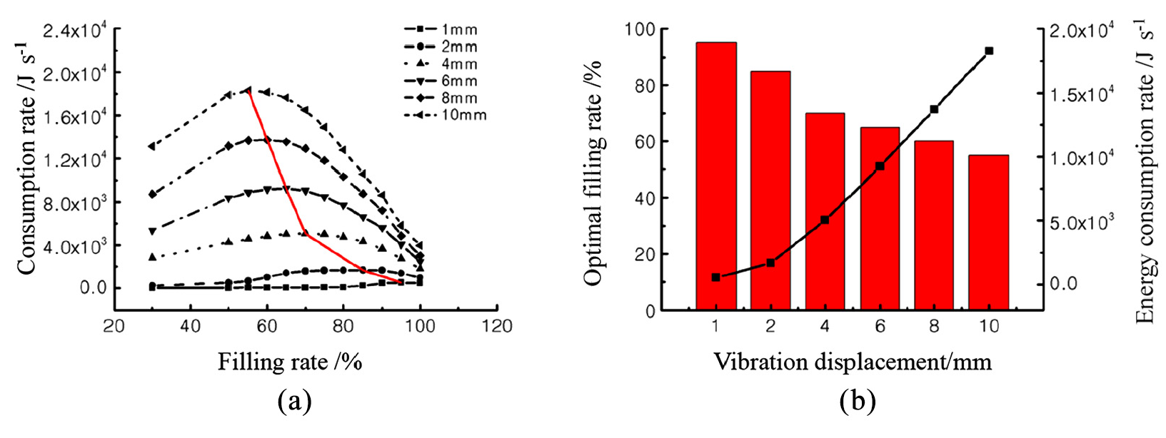
The influence of the vibration displacement on the optimal filling rate: (a) change of energy consumption rate with filling rate and (b) the optimal filling rate and the energy consumption rate change with vibration displacement.
Pipeline vibration reduction test
To investigate the vibration damping effect of the particle damper, a vibration table is used for the pipeline vibration reduction test, as shown in Figure 8. It is found that the particle damper shows a significant vibration reduction effect when clamping it at the largest vibration displacement place. Moreover, it can be seen from the frequency sweep tests that the pipeline has only a single formant within the frequency range from 300 to 440 Hz. Therefore, the frequency sweep test method is selected in this work to study the vibration damping effect at different mass filling rates, particle sizes, and structural particle dampers when the measurement point are controlled and the position of the damper remains unchanged. The sweep frequency range from 300 to 440 Hz, and the acceleration excitation is 1g.
The vibration table.
Comparison of different structural unit tests
Figure 9 depicts the filling rates of different structure unit as a function of the vibration acceleration. It can be seen that at the filling rate of 0, the vibration acceleration is slightly reduced compared with the unloaded pipeline, but this effect is lower than that of vibration reduction at the optimal filling rate. It can be seen from these results that the clamping damper has changed the mass distribution of the pipeline to certain but with limited influence on the vibration acceleration. The reduction of vibration acceleration mainly depends on the particle collision energy consumption.

Vibration damping effect of different structures: (a) 1 mm, (b) 2 mm, and (c) 3 mm.
The comparison of multi-unite and single-unite systems shows that the particles with the size of 1 and 2 mm exhibit better vibration reduction effect than those with the size of 3 mm. Besides, the vibration reduction effects of the multi-unite and single-unite systems are almost equivalent at the optimal filling rate, except that the multi-unite system shows better vibration reduction effect at other filling rates.
Comparative analysis of experimental and simulation
Figure 10 shows a comparison between the test and simulation data of the damper and those of the single unit structure. The left ordinate (hollow curve) represents the energy dissipation rate during the simulation process, while the right ordinate (solid curve) refers to the vibration acceleration of the pipeline in the test. It can be seen from Figure 10 that the filling rates of particles with the size of 1, 2, and 3 mm and good energy consumption effect are 85%–100%, 75%–97%, and 90%–100%, respectively, while the corresponding optimal filling rate under test conditions are 94.9%, 94.9%, and 97.9%. These results suggest that the filling rate is located within the range of filling rate showing better simulation energy consumption effect when the minimum vibration acceleration is obtained from the test.

The comparison between test and simulation: (a) 1 mm, (b) 2 mm, and (c) 3 mm.
Experimental study on vibration reduction of actual hydraulic pipeline
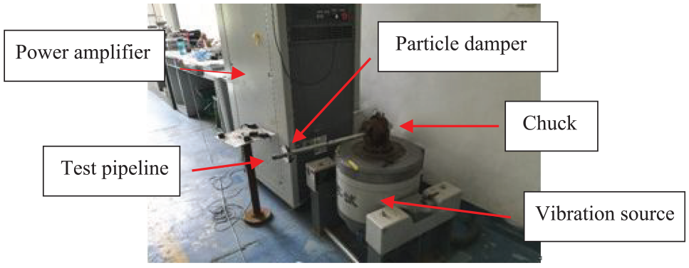
To test the vibration reduction effect of the particle damper designed in this paper on actual pipeline, the particle damper is installed on a hydraulic power source pipeline with the equipment structure shown in Figure 11. The speed frequency of the hydraulic pump and the pressure pulsation frequency are 25 and 175 Hz, respectively.

Hydraulic power source pipeline: (a) behind and (b) front.
For the comparison of the damping effects in different directions, the particle dampers are installed in horizontal direction, vertical direction, and both directions, respectively, as shown in Figure 12. According to Figure 13, there are three vibration acceleration measuring points, namely, X direction, Y direction, and Z direction in the tested pipeline. The effectiveness of the particle damper is proved by comparing the vibration acceleration at the three measurement points.

Installation methods of particle dampers: (a) horizontal direction, (b) vertical direction, and (c) both the two directions.

Vibration damping test site.
At the working pressure of 15 MPa, the vibration acceleration signals measured from the three directions (X–Z) before and after the installation of the particle damper on the pipeline are shown in Figures 14 to 16, respectively.

Comparison of vibration reduction results in X direction: (a) without damper, (b) the dampers installed in horizontal direction, (c) the damper is installed in vertical direction, and (d) the dampers are installed in both directions.

Comparison of vibration reduction results in Y direction: (a) without damper, (b) the damper is installed in horizontal direction, (c) the damper is installed in vertical direction, and (d) the dampers are installed in both directions.

Comparison of vibration reduction results in Z direction: (a) without damper, (b) the damper is installed in horizontal direction, (c) the damper is installed in vertical direction, and (d) the dampers are installed in both directions.
The comparison of Figures 14 to 16 indicates that the particle dampers clamped in both horizontal and vertical directions can achieve the best damping effect. However, it is worth noting that the results of the installation of the damper in both directions are similar with that of horizontal installation. The reason may lie in the fact that when the vibration acceleration is reduced to 10g, the amplitude is not enough to cause the particles in the damper to collide violently, resulting in the deterioration of vibration reduction effect. Another possible reason may be the setup of the damper, that is, the setup tightness of damper and pipeline has a great influence on the vibration reduction effect. Seen from the results of this study, the test effect of the damper is relatively stable.
Figure 17 illustrates the frequency spectrum of the vibration acceleration. It is worth noting that according to the test results in the X and Y directions, at the frequency of about 175 Hz, the vibration damping effect is better when the particle dampers are installed in both horizontal and vertical directions simultaneously. Moreover, the vibration acceleration in Z direction is lower than that of the pipeline without damper, but higher than the vibration acceleration in X direction and Y direction. This may be due to the fact that the vibration in the Z direction is smaller, resulting weak energy consumption effect.

Spectrum comparison of vibration acceleration: (a) X direction, (b) Y direction, and (c) Z direction.
Vibration reduction of aircraft hydraulic pipeline
In this research, the vibration reduction test is conducted on the real aircraft hydraulic pipeline when the engine is under ground running state, thereby investigating the vibration damping effect of the designed particle damper.
The particle dampers are installed at Positions 1 and 2, and the test positions are selected at the points of 3, 4, and 5, as shown in Figure 18. The vibration reduction effects at the points of 3, 4, and 5 at different engine powers are plotted in Figures 19 to 21. The vibration acceleration points in the Figures 19 to 21 are collected by the acceleration collector, which show the maximum vibration acceleration. It is clearly found that the vibration acceleration at the three measuring points are significantly suppressed when the vibration damper is installed. The larger the vibration acceleration, the more obvious the damping effect of the vibration damper.

The real aircraft hydraulic pipe system.
The point 3 at different engine powers.

The point 4 at different engine powers.

The point 5 at different engine powers.
It is verified by the above results that the particle damper has actual engineering vibration reduction effect.
Conclusions
In this paper, the particle damping technique was used in the hydraulic field. During the research, firstly, the mechanism of particle collision damping technology was explained. Secondly, the paper explained how to use the discrete element method to solve the problem of energy consumption between particles, and the analyses of the factors that affect the energy consumption. Moreover, the particle damper based on particle collision damping technology was designed and manufactured. In addition, the research work, such as the particle collision simulation analysis was also implemented. The specific conclusions of the whole paper are detailed as follows:
Aiming at the problem of pipeline vibration reduction, a particle damper applicable to pipeline vibration reduction based on the energy consumption principle of particle collision was designed in this work. The EDEM simulation was in perfect agreement with the vibration test results, and when the filling rate of particles in the particle damper is located within the range from 93.9% to 97.9%, the damper shows the best vibration reduction effect.
The vibration reduction test results of the particle damper on the hydraulic power source pipeline show that the vibration of the measuring points in the X-direction, Y-direction, and Z-direction were obviously suppressed, which verifies the effectiveness and practicability of the particle damper.
The vibration reduction test results of aircraft hydraulic pipelines at different engine powers by using particle dampers show that the vibration acceleration at different measuring points are all significantly reduced, and the damping effect becomes better with the increase of the vibration acceleration.
In conclusion, the particle damper designed in this paper shows practical engineering damping significance in the aspect of real aircraft pipeline damping.
However, there are still many contents which deserve in-depth study for particle dampers. For example, the material of the damper can be improved for mass reduction. In addition, the temperature effect of the particle damper may not be obvious due to the short experimental time. However, when the damper operates for a long time, the temperature will increase significantly, thereby affecting the characteristics of the material. All of the above aspects will be used as the direction of the future research.
Footnotes
Handling Editor: James Baldwin
Declaration of conflicting interests
The author(s) declared no potential conflicts of interest with respect to the research, authorship, and/or publication of this article.
Funding
The author(s) disclosed receipt of the following financial support for the research, authorship, and/or publication of this article: This work is supported by the National Natural Science Foundation of China (Grant No. 51675263) and Chengdu Aircraft Industrial (Group) Co., Ltd. which are highly appreciated by the authors.