
Abstract
The butterfly-shaped concrete-filled steel tube (CFST) arch bridge is an irregular bridge with unique esthetics. In this paper, this new shape of CFST arch bridge is introduced, and a refined three-dimensional finite element model (FEM) is established to evaluate static and dynamic behavior of the bridge. In order to reduce model errors, the FEM is calibrated according to numerical analysis and field tests. Static calculation results show that the butterfly-shaped bridge has good structural performance. The bending moment and axial force of the arch ribs increase when the camber angle of suspender changing from 15° to 50°. Dynamic test is carried out by ambient vibration testing under traffic and wind-induced excitations. The modal parameters of the bridge were calculated by the stochastic subspace identification method in the time domain. In terms of natural frequencies and mode shapes, the FEM analysis was validated by experimental modal analysis. The updated model thus obtained can be treated as a baseline finite element model, which is suitable for long term monitoring and safety evaluation of the structure in different severe circumstances such as earthquakes and wind loading in future.
Introduction
Concrete-filled steel tube arch bridge is the most commonly used bridge type in bridge construction in China due to the characteristics of lightweight, strong spanning ability, beautiful shape, round curves, and dynamic sense.1,2 Nowadays, with the rapid development of materials, computer-based analytical power and construction technology, the types, spans, and structural forms of concrete-filled steel tube arch bridge change with each passing day. A number of beautifully shaped arch bridges have emerged in the world.3–5 The butterfly-shaped concrete-filled steel tube arch bridge is one of them with unique esthetics. However, such arch bridges have complex stress forms, due to statically indeterminate, irregular shape, material and geometrical nonlinearity. 6 Therefore, it is necessary to fully understand both the static and dynamic behavior of such a kind of bridge.
Many researchers have investigated the static and dynamic behavior of arch bridges. Based on ambient vibration testing, Ren et al. 7 and Zong et al. 8 conducted the experimental and analytical modal analysis of a steel arch bridge with the method of the frequency domain-based peak picking and the time domain-based stochastic subspace identification technique. Yoshimura et al. 9 studied the natural vibrations properties and dynamic responses of a concrete-filled steel tubular pedestrian arch bridges under a moving vehicle. The research results clarified the response characteristics and response level of this arch bridge. Lu et al. 10 taken the Zhongshan irregular-shaped arch bridge as the research object to carry out both static and dynamic analysis. It is demonstrated that this esthetic type of bridge has reasonable structure, safety, and good dynamic performance. Huo and Han 11 investigated the nonlinear behavior and carried out corresponding parametric studies of the main girder of the butterfly-shaped arch bridge. Their result showed that the deflection and bending moment in the middle span of each girder increased with the increase in the camber angle of the main arch rib. Gou et al. 12 proposed a dynamic response analysis procedure, which applied to investigate the dynamic responses of a straddle-type concrete-filled steel tube tied arch bridge. Based on this method, the riding comfort of the trains was evaluated. The investigation results show that the impact factor of vehicle loads reaches the maximum value when the resonance of the bridge is induced by the moving vehicles. Yang et al. 13 analyzed the stressing state characteristics of a concrete-filled steel tubular arch model under spatial loads and the working behavior characteristics of arch structures are revealed in a particular view. Garcia-Guerrero and Jorquera-Lucerga 14 studied the effect of different pinned and stiffened hanger arrangements on the structural behavior of the tied-arch bridges. Thus, a low-cost and easy to install suspender connection mode is proposed. Based on experiment and finite element analysis of the Shizhi River Bridge, a three-dimensional finite element model (FEM) was developed by Lu et al. 15 Then an analytical modal analysis using different techniques was performed to determine the static behavior, natural frequencies, and mode shapes of the bridge.
However, few scholars have conducted in-depth analysis on the static and dynamic behavior of a butterfly-shaped arch bridge. In this paper, a special-shaped arch bridge of oblique arch ribs and without a cross brace at top of arch ribs is investigated intensively as a target bridge in terms of finite element calculation and field tests. This new special-shaped bridge, which is like a butterfly structure arch bridge, changes the structural form of the traditional arch bridge. A three-dimensional finite element model is established to carry out the static and dynamic analysis of such a bridge. Field tests were performed on the butterfly-shaped concrete-filled steel tube arch bridge. Suspender tensions of the finite element model are calibrated with those of field measured results. Combined with the measured values of the arch rib and main beam deflection, the static calculated results are compared with measurements. Dynamic test is carried out by ambient vibration testing under traffic and wind-induced excitations. The modal parameters were calculated by the stochastic subspace identification method in the time domain. In this paper, the flowchart of the numerical analysis and field tests is shown as Figure 1. In terms of natural frequencies and mode shapes, the FEM analysis was validated by experimental modal analysis. The updated model thus obtained can be treated as a baseline finite element model, which is suitable for long term monitoring and safety evaluation of the structure in different severe circumstances such as earthquakes and wind loading in future.

Flowchart of the numerical analysis and field tests.
Bridge description
The bridge as shown in Figure 2 is located in Xinmin Village, Xiaomiao Town, Feixi County, Hefei City, Anhui Province, which spans the Hefei Xinqiao international airport expressway. The configuration of this bridge is a half-through concrete-filled steel tube arch bridge, in which the single span is 58 m and the bridge deck width is 7 m. There are eleven pairs of suspenders on both sides with a spacing of 4 m. The main structure consists of welded steel pipes and steel boxes. The arch ribs are formed by ϕ500 × 20 mm circular steel pipes. The arch rib axis with a rise-span ratio of 1/2.8284 is a quadratic parabola in the same horizontal plane
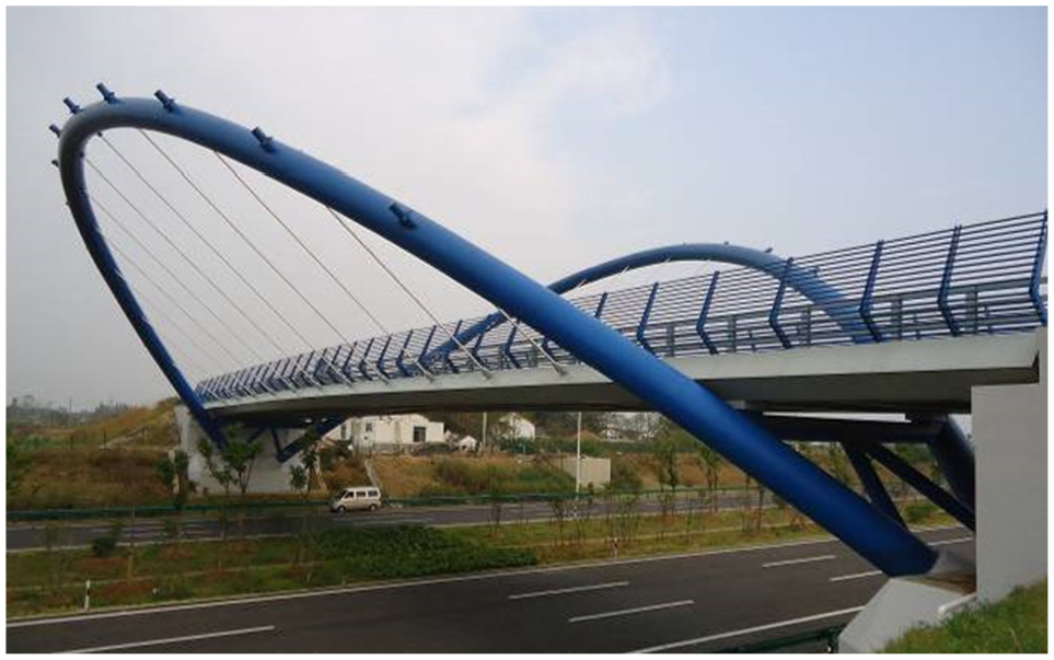
Arch bridge of butterfly shape.
The elevation and side views of the arch bridge are as shown in Figures 3 and 4 respectively. The bridge deck system is a steel-concrete composite structure formed by a box-shaped main longitudinal beam and a cross-beam which is arranged every 4 m along the bridge. I-shaped small longitudinal beam is installed every 2.5 m toward the transverse bridge and a cast-in-situ concrete bridge deck. The two ends of the bridge deck are supported on the arch rib cross brace by the plate rubber bearings that are evenly acted on the two arch ribs through the suspender rod. The material of beam is Q345D, while the material of the bridge deck is C40. The design safety level of this bridge is Grade I and the vehicle load is Highway-II. The designed speed is 30 km/h. The peak acceleration of ground motion is 0.10g and the corresponding seismic fortification intensity is 7°. The site category is comprehensively determined as Category II.

Elevation view of butterfly shaped arch bridge (mm).

Side view of butterfly shaped arch bridge (mm).
Field static load tests
The bridge was tested under traffic loading before the bridge was opened to traffic. Considering the field loading conditions, 300 kN loaded vehicles were used in this loading test. The conventional wheel distance, axle distance and axle weight of this vehicle are shown in Figure 5. According to structural configuration and experimental requirements, two heavy vehicles were selected for the test as shown in Figure 6.

The axle weight and dimensions of loaded vehicle.

View on vehicle positions during the static load tests.
The equipment required for the field test is shown in Table 1 below:
Test equipment.

For the long-term monitoring, some permanent measuring points are selected and used as the origin to establish a three-dimensional coordinate system, forming the relative relationship between each test point on the bridge and the subsequent viewpoint, as shown in Figure 7. For checking each other, two permanent measuring points are selected on the left and right sides of the bridge respectively, and one of the points is taken as the origin. Then a three-dimensional coordinate system is established, which takes the transverse direction as the X axis, the longitudinal direction as the Y axis, and the vertical bridge direction as the Z axis. Afterward the three-dimensional coordinates of the displacement measuring points of the bridge under the loading condition are measured.
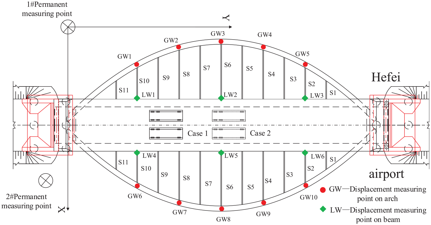
Vehicle loading cases, suspenders, and measuring points in the field static loading tests.
According to the most unfavorable working conditions, two loading cases were selected in the field test. As shown in Figure 8, the loading vehicle position is located at 1/4 span of the bridge in case 1 and 1/2 span in case 2.
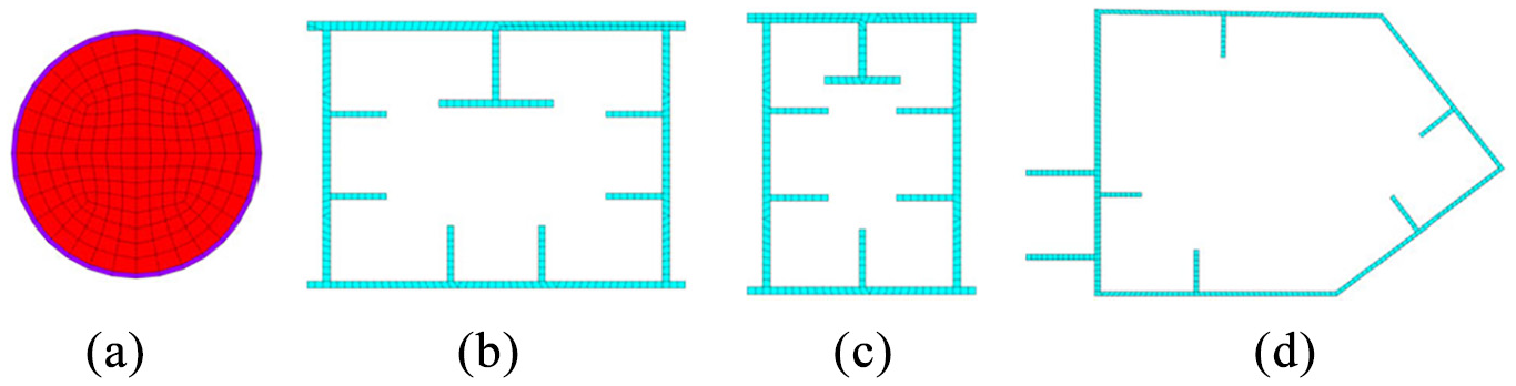
Section of the finite element model of the arch bridge: (a) section of arch rib, (b) section of end crossbeam, (c) section of middle crossbeam, and (d) section of main longitudinal beam.
The suspender numbers are S1, S2, S3… S11. GW1, GW2, GW3, GW4, and GW5 are upstream arch rib deflection measurement points, while GW6, GW7, GW8, GW9, and GW10 are downstream arch rib deflection measurement points. LW1, LW2, and LW3 are the deflection measurement points at the connection between the upstream main longitudinal beam and the flexible boom. LW4, LW5, and LW6 are the deflection measurement points at the connection between the downstream main longitudinal beam and the flexible boom. Due to the arch bridge symmetry, the upstream arch rib deflection (GW) and the downstream main longitudinal beam deflection (LW) are taken as the target measurement points. The calculation and analysis are performed by combining the finite element model with the measured data. During the simulation calculation, the load value of the front and rear axle weight of the test vehicle is applied as a node load at the position of the corresponding node of the test vehicle load.
Finite element model of butterfly shaped arch bridge
The longitudinal beam, cross-beam, arch ribs, and transverse brace of butterfly-shaped concrete-filled steel tubular arch bridges are typical space beam system structures. In order to accurately simulate the static and dynamic characteristics of the arch bridge, a refined three-dimensional finite element model of the arch bridge is established with the transverse direction of the bridge as the x-axis, the longitudinal direction as the y-axis, and the vertical direction as the z-axis. All the modeling and calculation processes are completed with the help of ANSYS Student 2020 R2.
From the loading process of the concrete-filled steel tube structure, it can be known that the steel tube and the concrete in the tube jointly participate in the structural stress, where two different materials will produce a stress superposition effect. Therefore, the full-bridge arch ribs, cross beams and other beams are simulated using the Beam188 element based on the Timoshenko beam theory which includes shear-deformation effects. The element can be a linear, quadratic, or cubic two-node beam element in 3-D setting by key option parameters and provide options for unrestrained warping and restrained warping of cross-sections. Meanwhile, Beam188 element has six degrees of freedom at each node, which includes translations in the x, y, and z directions and rotations about the x, y, and z directions. This element is well-suited for linear, large rotation, and large strain nonlinear applications and can customize the complex cross-section shape of the structure. A cross-section associated with this element type can be a built-up section referencing more than one material.
The bridge panel is simulated by element Shell181, which is suitable for analyzing thin to moderately-thick shell structures. It is a four-node element with six degrees of freedom at each node, namely translations in the x, y, and z directions, and rotations about the x, y, and z-axes. Shell181 is also well-suited for material plasticity, stress rigidity, linear, large rotation, and large strain nonlinear applications. The change in the shell thickness is accounted for the nonlinear analyses.
The suspender is simulated by the element Link10. It is a 3-D truss element that is useful in a variety of engineering applications. This element with three degrees of freedom at each node can be used to model trusses, sagging cables, links, springs, and so on. Tension-only (cable) and compression-only (gap) options are supported to simulate the slack of a cable or suspender. As in a pin-jointed structure, no bending of the element is considered. Plasticity, creep, rotation, large deflection, and large strain capabilities can be included.
According to the actual shape and section sizes, the section of longitudinal beam, cross beam, arch rib, and other components are defined by the user, and the sections of the three-dimensional finite element are shown in Figure 8. The material properties of each component are determined according to the actual measurement or relevant specifications.
The three-dimensional finite element model of the whole bridge is shown in Figure 9. This finite element calculation model of the butterfly-shaped concrete-filled steel tube arch bridge has 11,021 nodes and 8402 elements. Among them, there are 1980 beam elements, 6400 bridge deck shell elements and 22 bar units. The boundary conditions of the bridge are hinged at one end and slid at the other end.

Three-dimensional finite element model of the butterfly shape arch bridge.
Basic materials used in this bridge are steel and concrete. The material constants used are summarized in Table 2 when the finite element model of the butterfly shape arch bridge is established.
Material properties.

Static analysis of butterfly shaped arch bridge
To reduce the error between the numerical calculations and experiments, model updating is necessary.16–19 In this paper, the suspender tension is taken as a single objective response. Then, combined with measured value of the suspender forces under dead loading, the finite element model of this butterfly shaped arch bridge is calibrated. The results are presented in Table 3.
The suspender tensions before and after calibration.

It can be observed from Table 3. There is a certain difference between the calculated and measured values of each suspender force. Before the calibration of the finite element model with field measurements, the maximum error between the calculated and measured values of the suspender force reached 42%. After the calibration of the finite element model, the maximum error between the calculated and the design value of the suspender force numbered S1, S2, S10, S11 reduced below to 6.08%, while the maximum error between the calculated and the measured value of the suspender force numbered S3, S4……S9 reduced below 0.78%, and the minimum error is 0.52%. Therefore, it is demonstrated that after such a correction, the errors between the calculated values and the measured values are significantly reduced.
The calculated and measured values and their variations of the arch rib deflection under two loading cases are compared as shown in Figure 10. It can be observed that the calculated arch rib deflections match the measured deflections under two loading cases, especially for the vertical deflections of the arch rib. The experimental and calculated values of the arch rib deflection are less than specifications value L/600 = 96.67 mm indicating that the structural performance meets the code requirements.
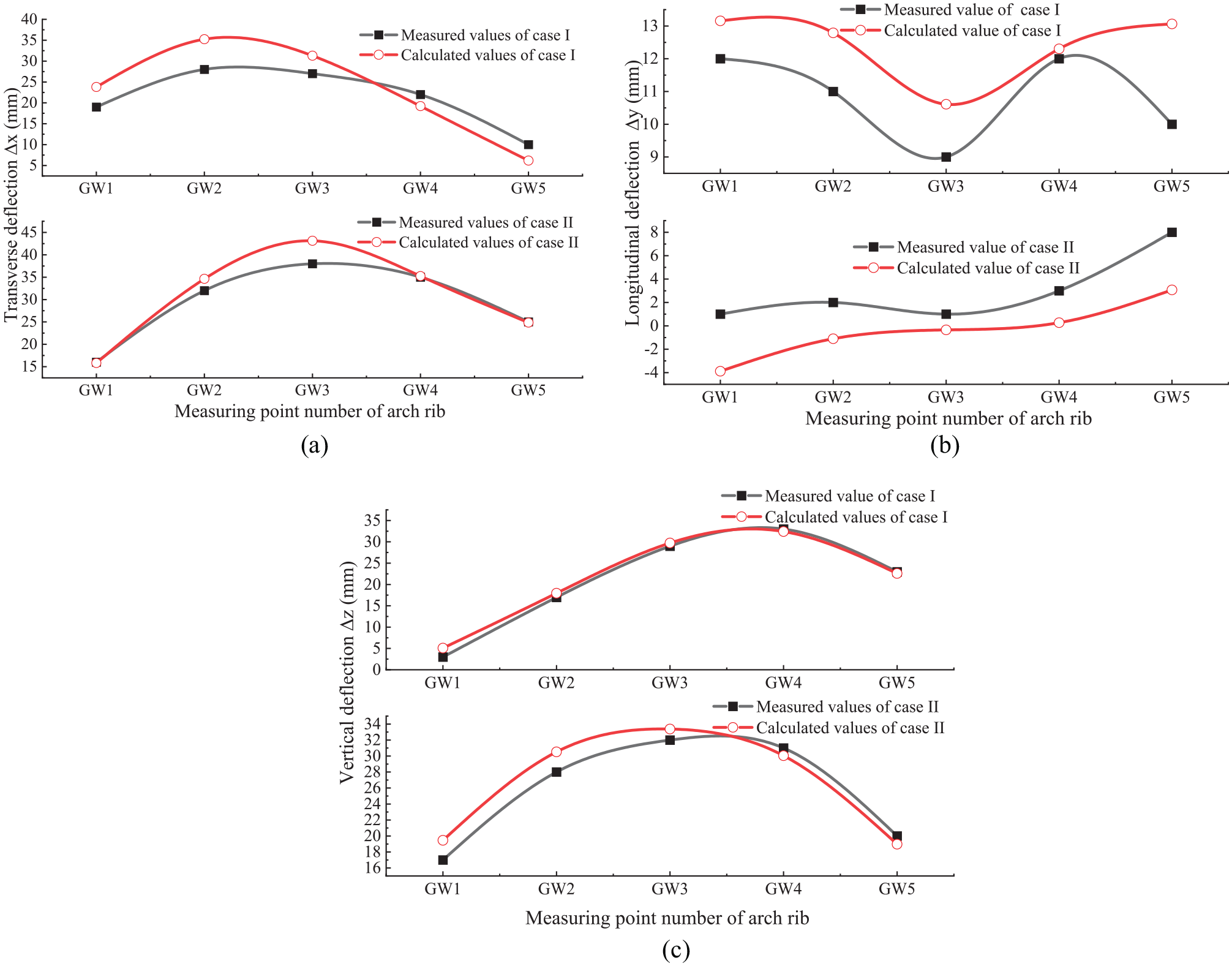
Calculated and measured value variations of the arch rib deflection under two loading cases: (a) transverse deflection curve of arch rib, (b) longitudinal deflection curve of arch rib, and (c) vertical deflection curve of arch rib.
Both calculated and measured vertical deflection of the bridge deck system are contrasted in Figure 11. It can be found that the calculated and measured vertical deflection curve of the main longitudinal beam fits well. The measured deflection is less than the calculated one, which shows that the stiffness of the frame beams system is large.

Vertical deflection of bridge deck along main longitudinal beam.
The research above suggests that the correction method of suspender cable force proposed is feasible and correct. In order to study the influence of arch rib inclination angle on the mechanical characteristics (mainly bending moment and axial force) of arch rib, several finite element model of butterfly arch bridge with different inclination angles of arch rib and suspender is established to address these issues. For suspender arch bridge, the vertical force exerted by suspender on main girder is very important.
20
Taking the vertical component of suspender force (marked

Force diagram of suspender.
It can be seen from the decomposition of force in Figure 12:


where
The iterative control equation is as follows:

where ε is the error control value. We can make ε equal to 0.1 or a smaller value.
Each model can meet the requirements of the control equation after 200 to 300 calculations. Because of the symmetry of the structure, the bending moment and axial force diagram of one side arch rib of the arch bridge are extracted after iterative calculation.
As shown in Figure 13(a), the distribution of bending moments is regular. The bending moment of arch foot and mid span is mainly positive, and the bending moment at arch foot is greater than that at mid span; The maximum negative moment of arch rib is located at 1/6 span and 5/6 span of bridge. According to the calculation results, when the inclination angle of arch rib varies between 15° and 50°, the maximum negative bending moment is changing between −407.18 and −772.08 kN m, and the bending moment increases with the increase of the inclination angle of suspender and arch rib. At the 1/3 span and 2/3 span of the bridge, there are transition sections of positive and negative bending moment, where the bending moment tends to zero.
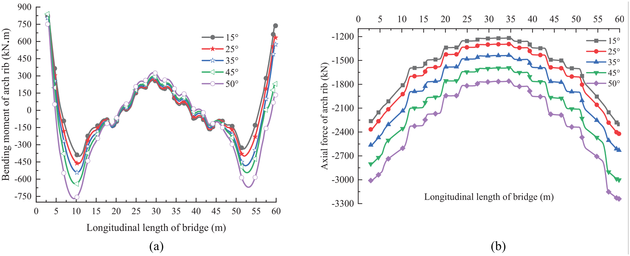
Diagram of axial force and bending moment of arch rib with different suspender inclination: (a) bending moment diagram of arch rib and (b) axial force diagram of arch rib.
Figure 13(b) shows the results obtained from the studies that the axial pressure of arch rib increases with the increase of arch rib inclination, when the inclination angle of arch rib varies from 15° to 50°. From the distribution of axial force, the closer to the arch foot, the greater the axial pressure, and the axial pressure in the middle span is the smallest, which is in line with the mechanical characteristics of arch rib.
The above diagram also illustrates a result: when the inclination angle of suspender and arch rib changes from 15° to 35°, the maximal negative bending moment and axial force increment of arch rib are relatively small; On the contrary, when the inclination angle of suspender and arch rib changes from 35° to 50°, that are relatively big.
Ambient testing and modal identification
The natural frequency and mode shape are the inherent characteristics of the structure. They are important parameters for the dynamic performance and design of bridge structures, such as wind resistance, seismic design, and vehicle-bridge coupling vibration analysis. In general, the modal parameters of structure-free vibration can be solved21,22:


where
The equation to solve the natural frequency of structure can be obtained by eigenfunction as follows:

where
Ambient vibration testing of bridge
Base on the theory, the modal parameter (frequencies, mode shapes, and damping ratio) identification can be obtained, while the measured time domain data are available from testing. There are two main kinds of modal tests that are carried out on bridge structures: forced vibration tests and ambient vibration tests. In view of the advantages and disadvantages of the two methods, the field modal testing on the butterfly arch bridge was carried out using the method of ambient vibration, which does not affect the traffic on the bridge. The equipment used to measure the response consisted of wireless velocity transducer linked to their own data acquisition system DH5907N. The system with the characteristics of small size, easy to carry, and built-in lithium battery, use wireless synchronization technology to transmit time domain data, as shown in Figure 14. Now the equipment has been widely used in the experimental data acquisition and modal analysis of bridges, large buildings, and other structures.

Connection of multiple collectors.
All measurements were taken by placing the collectors on the pavement due to the limited access to the actual floor beams and the testing time constraints involved. Measurement stations were chosen at both ends of the arch span and each joint of suspenders connected to the deck. As a result, a total of 30 locations (15 points per side) were measured. The locations of measurement stations and distribution of wireless velocity transducers are shown in Figure 15. Four test setups were conceived to cover the planned testing area of the arch span of the bridge. Two reference locations, hereinafter referred to as the base station, were selected based on the mode shapes from the preliminary finite element model. Each setup consisted of two base wireless velocity transducer stations and seven moveable wireless velocity transducer stations.

Distribution of wireless velocity transducers: (a)Signal transmitting equipment, (b)Signal receiving equipment.
Table 4 shows the distribution of the different stations per setup. S1, S2 are the two test setups for the left-hand lane, while S3, S4 are the two test setups for the right-hand lane of the bridge arch span. Data from four test setups for each of the right-hand lane and left-hand lane were measured. Once these data were collected in one setup, the moveable stations were moved to the next locations while the base stations remained stationary. This method was repeated four times to get measurements on all stations. Each setup (S1, S2, S3, S4) yields a total of two sets of data from base station and seven sets of data from moveable stations. The sampling frequency on site was chosen to be 100 Hz to capture the short-time transient signals of the ambient vibration in detail. The ambient vibration measurement was simultaneously recorded for 500 s at all velocity transducers, which resulted in total 50,000 data points per data channel. During all tests, normal traffic was allowed to flow over the bridge at normal speeds.
Different stations per setup.

Data processing and modal identification
With the help of MACEC, a MATLAB toolbox for civil engineering construction modal analysis, the data processing and modal identification for the butterfly bridge are carried out. Once the measured time domain data are available from testing, the data of each channel can be differentiated to get the acceleration data. A typical acceleration data (station L1-8) is shown in Figure 16. When all the acceleration data are obtained, the modal parameters of the bridge can be calculated by the stochastic subspace identification (SSI) method in the time domain. A window length of 1024 data points was selected to obtain a much smoother spectrum in MACEC. For obtaining a good model for modal analysis applications, it is a better idea to construct a stabilization diagram, which can help the engineers to select the true modes since the stable poles refer to the true natural frequencies. The typical stabilization diagram of SSI is shown in Figure 17 for the vertical acceleration data.

Vertical time history acceleration data of station L1-8.
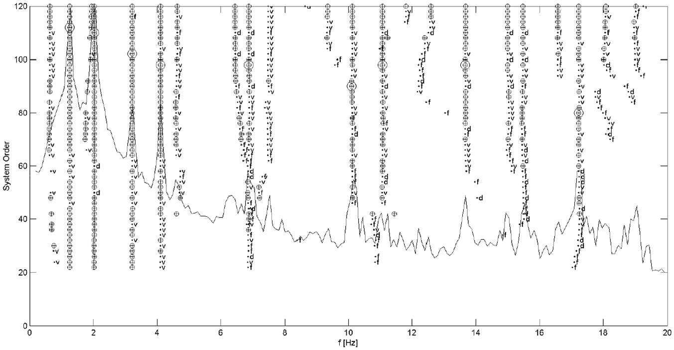
A typical stabilization diagram for vertical data.
The theoretical modal parameters can be calculated by the finite element model established and updated in the third section. From Table 5, it can be seen that the frequencies agree well between FEM and SSI methods. The good quality mode shapes have also been extracted. The first six vertical mode shapes of the bridge identified by the method of finite element and SSI are given in Table 6. It is demonstrated that the identified mode shapes agree well.
Identified and calculated frequencies.

Typical vibration modes of butterfly arch bridge.

There are many factors (boundary conditions, material properties, assumptions, etc.) that affect the accuracy of finite element models. Therefore, the FEM has to be checked or validated by field test results to verify the current conditions of the butterfly bridge. Generally, it is hard for the experimental and numerical frequencies of a bridge to match perfectly. As can be seen in Tables 5 and 6, the first and second natural frequencies of the bridge measured are slightly smaller than the theoretical calculation, while the third to sixth natural frequencies are slightly larger. But the error is acceptable. The measured vibration mode shapes of each order are consistent with theoretical calculation. On the basis of these results, the FEM analysis was validated by experimental modal analysis in terms of natural frequencies and mode shapes. The updated model thus obtained can be treated as a baseline finite element model, which is suitable for long term monitoring and safety evaluation of the structure in different severe circumstances such as earthquakes and wind loading in future.
Conclusions
The butterfly-shaped concrete-filled steel tube arch bridge is an irregular bridge with distinctive esthetics. Due to the irregular butterfly-shaped arch ribs, the structure of such an arch bridge becomes complicated. Take a real constructed butterfly-shaped concrete-filled steel tube arch bridge as a target bridge, both static and dynamic analysis are carried out to better understand the structural behavior of such a bridge under loading. Field static testing under loading vehicles was performed on the targeted bridge. The calculated deflections of the arch rib and main beam deflection are compared with those of field measurements. The outcomes are of help to the design and maintenance of the similar butterfly-shaped arch bridge. The following conclusions can be drawn.
The suspender tensions and modal parameters (frequencies and mode shapes) of the finite element model are calibrated with those of field measured results. After such correction, the errors between the calculated values and the measured values are significantly reduced. This method can provide a reference for the initial finite element model modification. The updated model thus obtained can be treated as a baseline finite element model, which is suitable for long term monitoring and safety evaluation of the structure in different severe circumstances such as earthquakes and wind loading in future.
In the two fields loading cases, it is demonstrated that the calculated values of the deflections of arch ribs and main longitudinal beams fit well with the measured values, especially for the vertical deflections. It is observed that the measured deflection values are all less than the calculated deflection values, indicating that the integral stiffness of the full-bridge arch ribs and longitudinal and transverse frame system of the bridge deck are relatively large, which meets the requirements for the bridge opening. The results of the experiment indicate that the targeted bridge has a good structural performance under two statically loading cases.
The research has revealed that the bending moment and axial force in the arch rib are related to the inclination angle of arch rib and suspender for butterfly arch bridge. When the inclination angle of arch rib varies from 15° to 50°, the axial pressure at the arch foot and in the span of arch rib increases with the increase of inclination angle; The closer to the arch foot, the greater the axial pressure, and the minimum axial pressure is in the middle span; The negative bending moment of arch rib is near 1/6 span and 5/6 span of bridge; At the 1/3 span and 2/3 span of the bridge, the positive and negative bending moment in the arch rib is the transition section, where the bending moment tends to zero.
Footnotes
Handling Editor: James Baldwin
Declaration of conflicting interests
The author(s) declared no potential conflicts of interest with respect to the research, authorship, and/or publication of this article.
Funding
The author(s) disclosed receipt of the following financial support for the research, authorship, and/or publication of this article: This work was supported by the National Natural Science Foundation of China under Grant No. 51778204.