
Abstract
Presented herein is a mathematical model employing differential equations formulation for brush seals used in gas turbine engines. These components are used to seal the bearing chamber from the environment and reduce the loss of lubricant in the atmosphere, ensuring a MTBR long enough to have required the change the seals only during the engine overhaul operation. The model assumes a single curved bristle loop in the form of a curved-bridge beam subjected to the influences of complex external loads (static and dynamic). Further, a model for clustered bristles is proposed. Specifically, the static forces acting on the curved-bridge beam include the weight of the oil capillary attached to the beam, the weight of the beam itself, the capillary force developed between the surfaces of the bristles in the brush and the temperature gradient. The dynamic forces include the leakage oil pressure and the rotation of the shaft. This complex loading induces a nonlinear large deflection on the curved-bridge beam. Also, the temperature gradient present on the bristles during the gas turbine engine operation generates a change in the geometry of the beam and in the magnitude of the forces acting on the bristles modeled as beams. In the present model, the weights are assumed as uniformly distributed forces on the surface of the beam while the capillary forces and the force generated by the rotating shaft are considered to be non-uniform. The equation expressing the curvature of the beam under general loading force is developed and one can choose the appropriate method of solving the generated differential equation after the expression of the general force is defined. Hence, the ordinary differential equation describing the nonlinear large deflection of the curved-bridge beam will be derived using general nonlinear elasticity theory.
Introduction
Machine elements concluded long time being among the top research subjects as most of the steady behavior of such machine elements was modeled and the output is quite well predictable. However, there are aspects that need to be addressed as certain such components might not be providing the expected performance. Development of a comprehensive model is useful in understanding the behavior and the performance improvement of the component. Separation of the oil-contained atmosphere in bearing boxes from the atmosphere preoccupied the design community. Recently, few now modeling protocols were proposed1,2 for the performance analysis of classical labyrinth seals. Although the interest in brush seals patented over 60 years ago, 2 their performance and means to improve those are significant within the aero engine manufactures, the subject which, however, occupies a very narrow niche in the technical literature. Hence, leaks in brush seals was modeled and compared with experimental results. 3 Given the complex interaction between the bristles in the seal, the accurate deterministic model is not feasible while modeling of such, however, simple components, may require advanced hierarchical modeling.4,5
The reduction of oil consumption in gas turbine engines is important from the reduction of both maintenance costs and the oil loss with its negative environmental impact. 6 From this perspective, the development of brush seals for gas turbine engines represents a promising method that satisfies both the aforementioned criteria.7,8 The working principle of the brush seals consists of sealing the oil by means of the multitude of curved bristles made from carbon, steel, or other materials that slide together on the rotor surface during the operation of the engine being positioned very close to each other. The analysis of the behavior of the bristles during their operation provides important information for their dimensional and material selection. Presented in Figure 1 is a front view of a brush seal.

(a) Macroscopic view of the brush seal and (b) close-up view of the bristles.
From the technical literature one can see that the deflection of beams/cantilever beams under various boundary conditions and loading conditions has extensively been studied. The differential equation that describes the nonlinear deflection of a cantilever beam under the influence of a concentrated force at its tip was solved based on complete first- and second-kind elliptic integrals. 9 The mathematical study of the large deflection of non-prismatic cantilever beams under the influence of various types of continuous and discontinuous loadings involves mostly numerical methods. 10 An exact solution for the governing differential equation was investigated in Changizi 11 and Amin Changizi and Hendrick. 12 The analytical solution of the ordinary differential equation (ODE) employs the Lie symmetry method. 12 All the exact solutions found are validated with numerical means. Depending on the coefficients in the considered ODE, either the perturbation method 13 or advanced differential quadrature method 14 is considered from the numerical point of view. Further variations of parameters can be studied after solving the governing ODE by deriving the Cauchy stress tensor.15,16
In the present work, a mathematical model is developed assuming a single curved carbon bristle loop as a curved-bridge cantilever beam subjected to the influence of several external forces and moments. The loads are considered to be both static and a dynamic in nature. The applied complex loading induces a nonlinear large deflection on the cantilever beam. Herein, general nonlinear elastic theory is employed to derive the nonlinear large deflection of the cantilever beam. Firstly, the equation expressing the curvature of the cantilever beam under general force loading is considered. The general force in this equation is related to the above-mentioned efforts. Secondly, the modeling accounts for the temperature gradient effect by means of a temperature dependent coefficient. Consequently, the ODE transforms into a nonlinear partial differential equation (PDE). Solutions of the ODE or PDE can be obtained once the general force has been defined. However, due to the disparity between the order of magnitude between the dimensions of the cantilever beam and the forces acting on it, the constitutive differential equation is stiff. The numerical analysis of a stiff differential equation might raises challenges.
Model development
The mathematical model of brush seal can be derived by considering each brush as a curved-bridge cantilever beam (CBCB). The CBCB is subjected to external static forces. The CBCB under general forces could have a nonlinear deflection. Although nonlinear deflection of beams subjected to various types of forces and boundary conditions have been extensively studied, the special case of boundary conditions where the free end of a cantilever beam during deflection contacts an adjacent beam 17 is further analyzed. Herein, six cases are considered: (i) large deflection of a beam under the influence of a general force, (ii) large deflection of a CBCB under the influence of an eccentric point force, (iii) large deflection of a CBCB under the influence of a point force at its free end, (iv) dynamical behavior of cantilever beam, (v) the equivalent moment large deflection of several CBCB due to loading and contact and the friction forces between them, and (vi) experimental results.
Large deflection of a beam under the influence of a general force
As mentioned above, a first step in solving this case consists in the derivation of the ODE used for the modeling. Presented in Figure 2 is a schematic of single bristle modeled as a cantilever beam with a general boundary condition, included fixed ends, under the action of a distributed force

A beam loaded with general force.
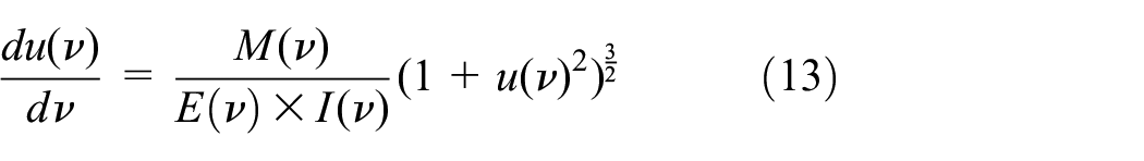
The governing equation for this case is given by equation 18 representing the general curvature of a beam under the action of a general force. 17 The general force consists of the uniform forces generated by the aforementioned weights and the non-uniform forces due to the capillary phenomena. The leakage oil pressure and the rotating shaft force are considered in this case as point forces.

Left side of the above equation is the curvature of the beam.
The general solution of equation 18 is obtained by using the, Lie symmetry method. In this method first one should define the infinitesimal transformation of the ODE as following:
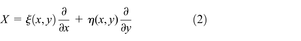
where X is an operator. This operation acts on a one parameter transformation group. The group can be defined by two functions,

Applying the operation X from equation (2) on a second order differential equation like:

will yield to the following equation:

By decomposing (5) into a system of PDEs,
For equation (1), ω is given by:

For equation (1) can be shown that:
Canonical coordinates can be calculated as 12 :

One can show that:


Any canonical coordinates must satisfy the following conditions 17 :

The reduced form of the transformation becomes:
The substitution of the transformation (10) into equation (1) gives:
Equation (13) is a first order ODE and can be solved by using the Lie symmetry method. As above, for a first order differential equation like:

The following relation should be satisfied for infinitesimal transformation

Equation (13) can be written based on (14) as following:

Substituting the expression (15) in the equation (16) gives:

It can be demonstrated that:

Therefore:

The respective canonical coordinates are calculated as:


These canonical coordinates yield the following solution:

Substituting the equation (12) in the expression (23), y(x) becomes:
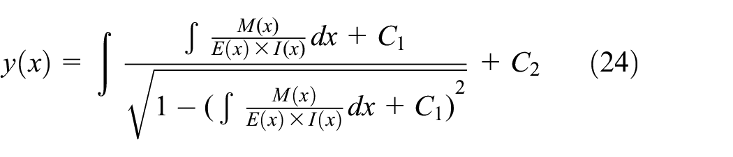
This solution is expressed as a function of the constants
Large deflection of a CBCB under the influence of an eccentric point force
Shown in Figure 3 a curved single brush seal under an eccentric force.

Large deflection of curved beam under an eccentric force.
The above picture illustrates a curved single bristle seal that is under an eccentric point force P.
The governing equation for a bristle is as the following 6 :

where:


The boundary conditions of the generated ODE are:

Using same method that as above, one can show that if:

The solution of (23) is:

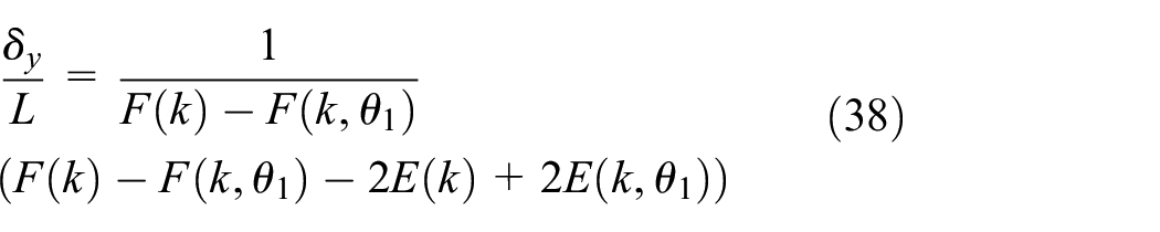
From equations (25) and (26), one can write equation (33) as:


Figures 4 to 9 show the results of the numerical analysis of equations (35) to (37) for the following data: diameter of a bristle is 5 μm, its length 11 mm, u is assumed to be zero, E = 135 GPa and density 1440 kg/m3, and the final angle

Numerical solution of the integral equation (35) for

Numerical solution of integral equation (36) for

Numerical solution of the integral equation (37) for

Variation of the deflection y versus the deflection x in the equations (36) and (37) for

Variation of the deflection ρ versus the deflection x in equations (35) and (36) for
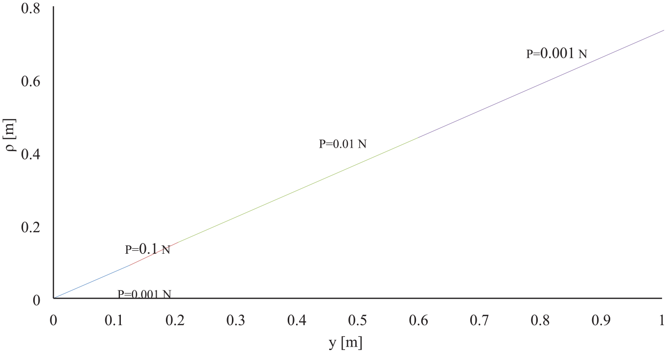
Variation of the deflection ρ versus the deflection y in equations (35) and (37) for
Large deflection of a CBCB under the influence of a point force at its free end
The dimensionless solution for the deflection is calculated from equation (1) shown below. 12 Presented in Figure 10 is the notation used in the calculation of the large deflection of a cantilever beam loaded with a point force at its tip. Presented in Figure 11 is the numerical solution of equation (1).

Large deflection of a cantilever beam – point force acting at the free end.

Dimensionless numerical solution of the equation (1).
where:

Where P is point force, E is Young modulus, and I is moment of inertia
Dynamical behavior of cantilever beam
Free vibration of a beam (Figure 4) can be calculated from the following equation 19 :

Whereas Y is the deflection of the beam, t is time, A is cross section of beam, E Young modulus, and I is moment of inertia. Natural frequency of a cantilever beam can be driven from solution of the above equation 19 :

Whereas:

m is the mass of beam and L is length of beam.
The first natural frequencies of the above beam is:

The equivalent moment large deflection of several CBCB due to loading and contact and the friction forces between them
One can replace the moment of inertia of the brushes in an arc of a brush seal at an angle of 4°–5°, with an equivalent moment of inertia that can be calculated as follows. Shown in Figure 12 a cross section of on a row of beams.
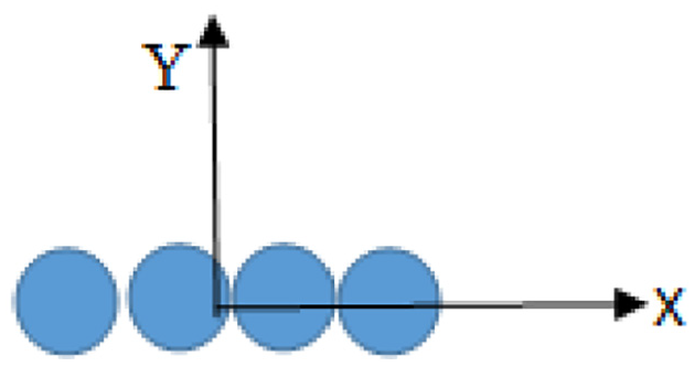
n number of beams in a line.
The moment of inertia for each circular beam is

where:
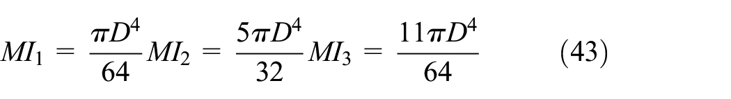
If k rows of beams are considered like in the Figure 13, one can show that total moment of inertia can be calculated as follows:
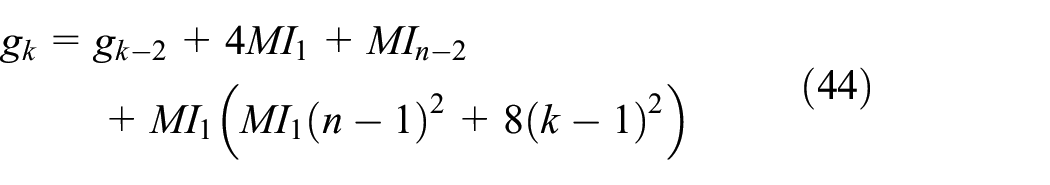

“n” Brushes in x axis and k brushes in y axis a matrix.
where g1 = MIn,
Experimental results
The computation of the large bristle deflection as a function on the load applied to its extremity, shown on section (i), will be confronted with experimental results produced with the ATM-02 test bench at the Université Libre de Bruxelles. The test bench consists in air and oil supplies, connected on a rotating unit where the brush seal is wedged between high and low pressures cavities, and mounted on a shaft assembled with disks of several diameters, thus over a large range of interference levels. A torque sensor, coupled in-line to the shaft, measures the frictional torque of the brush seal sample (Figure 14). More information on this test bench is available in the literature. 17 Two carbon fiber brush seals will be submitted to low speed runs at 200 RPM and without differential pressure, and to various interference levels. However, putting in relation the experimental results with the theoretical ones requires setting a certain number of assumptions and approximations, given the complexity of measuring such low contact loads and displacements.

Experimental setup and close up on brush seal mounting on rotor.
First, it is important to specify that these carbon bristles are assembled into windings that are rolled around an annular core as shown on Figure 15. Two metallic plates are then crimped into another to form the brush seal casing. Consequently, the bristles all converge toward the brush seal center, and have no lay angle. Also, an interference level is defined when a rotor disk is mounted with a higher diameter than the brush seal inner diameter. As the rotor disk is mounted after the brush seal, the bristles are oriented toward the downstream cavity. This configuration leads to a setup where a normal load N is applied on the bristle tip when the latter is deflected, as shown on Figure 16.

Cross section of a brush seal.
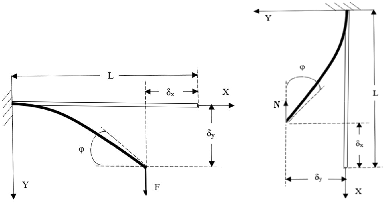
Equivalence between two force systems over one bristle.
In order to retrieve the load F that is necessary to upset the bristle tip over a δy displacement which will establish its equivalence with another force system composed of a cantilevered beam with the same predetermined deflections δx and δy. In addition, a load N along the x-axis will be defined as the required force to keep the beam with the same deformation, as illustrated on Figure 16.
The maximum bending moment at the fixed end of the cantilevered beam equals:

Where δx is imposed and equal to the interference of the brush seal. Whilst it could not be measured, δy can be estimated as a function of δx/L by using Figure 11, given that the dependency between these displacements is not influenced by the intensity of the load F. L is the bristle length, and the force N is yielded from the brush seal torque.
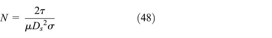
The frictional torque developed on one bristle is retrieved by dividing the brush seal torque by the total number of bristles, while assuming the circumferential density of the brush seal is homogeneous. The resultant of the frictional forces over all brush seal bristles is obtained by dividing the frictional torque by the rotor radius. Then, the frictional force applied on one bristle is retrieved by dividing the total frictional force by the number of bristles (known through the brush seal circumferential density and the seal diameter). Ultimately, the normal force N is computed in virtue of Coulomb’s law, by dividing the frictional force by the friction coefficient of carbon over steel-made rotor that is evaluated to 0.14.

So, T can be calculated as following:

N will be:
The characteristics of both samples, provided by French manufacturer Technetics, are displayed on Table 1.
Geometrical characteristics of the brush seals samples.
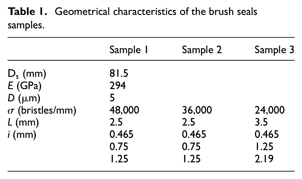
Brush seals torque measurements were performed using a Kistler 4503A torque sensor operating on the strain gauge principle. It could measure up to 2 Nm with an accuracy of 0.1%. Three carbon fiber brush seals were submitted to low speed runs at 200 RPM, without differential pressure, and to three interference levels. Interference is the (negative) distance between the brush seal inner diameter and the rotor diameter. Each run on one sample with one interference level was performed three times, leading to a total number of 27 experiments. As the brush seal torque was recorded every second, it was averaged over a time span of 6 s, then over the three runs for a combination brush seal sample/interference level.
With all the available data, the ratio of the radial displacement of the bristle tip (thus the interference δx) over the bristle length is computed as a function of the dimensionless parameter

Dimensionless contact loads on bristles versus dimensionless numerical solutions for three brush seal samples.
Conclusions
The study of the nonlinear behavior of the cantilever beam shows that the relation between large deflection and force has generally an elliptical integral analytical solution.
Also, for contact problems the analytical solution could not be obtained.
However, the present analytical analysis shows that calculating the friction force and the deflection of the bristles is possible.
Moreover, a general nonlinear relation for the forces between the bristles together with a method to calculate the equivalent moment of inertia of the brushes in an arc of a brush seal are presented.
Finally, despite the numerous hypothesis and assumptions required to retrieve the contact loads as a function of the bristle tips deflections, the estimation of contact loads for a given radial tip displacement demonstrated good agreement with the numerical solutions.
The results of this work could be used to produce seals that reduce the loss of oil during the operation of the engine.
Footnotes
Appendix
Handling Editor: James Baldwin
Declaration of conflicting interests
The author(s) declared no potential conflicts of interest with respect to the research, authorship, and/or publication of this article.
Funding
The author(s) disclosed receipt of the following financial support for the research, authorship, and/or publication of this article: This work was founded by MITAC Canada and Tecnolub within the framework of the project Research topics in oil lubrication for aircraft gas turbine engines.