
Abstract
An important step in the production cycle of pressing the expanded polystyrene is cooling of the mold and the molding. The paper describes the execution and analysis of experimental measurements in order to identify the influence of the cooling system on the quality of products produced by the technology observed. For the purpose of the experiment, a test mold with specific properties of the mold parts of the mold cavity was designed and manufactured. By means of the measuring circuit, the knowledge of the course of temperatures in the mold cavity during the pressing cycle was obtained. At the same time, the temperature distribution on the moldings and in the mold was monitored by means of a thermal imager. Two press cycles, with and without water cooling, were performed in course of the tests. Subsequently, the quality of the test pieces produced was checked. Based on the experiments conducted, the parameters influencing the water-cooling process of the mold for the production of expanded polystyrene have been identified. A significant element of the water-cooling system, which affects the quality of products and the technological process, is the application of spray nozzles – their location, orientation, and density. In order to optimize the cooling process observed, a multiple-nozzle spray head has been designed to produce water mist as a tool for more efficient distribution and application of the coolant.
Introduction
Expanded polystyrene (EPS) products are widely used in the construction and packaging industries, mainly due to their good insulating and mechanical properties. The most represented products made of expanded polystyrene include fittings for packaging and transport purposes. Expanded polystyrene is an incredibly lightweight, excellent heat, and cold insulator with superior chemical resistance. Nowadays, when we try to minimize the negative impact of plastic materials on the quality of the environment, expanded polystyrene products are still used as components for the automotive industry or in construction. Plastics are one of the worst materials to recycle and they are the most damaging to the environment, as they are present on the market in many forms. However, in terms of recycling, EPS is considered a well-recyclable material.1,2 It can be recycled both chemically and mechanically up to 20 times without significantly losing its physical properties. About 98% of EPS is made up of air and 2% of material – it’s an efficient use of materials and resources without the negative side effects. EPS production is also environmentally friendly – clean technology with low water consumption and very low emission levels is used. Any production waste is reprocessed into another product.
The technological process of EPS product production is based on steaming which, by supplying steam energy, increases the volume of the polystyrene or polypropylene beads and allows them, at a certain temperature, to assume the shape of the mold. The second, no less important activity is cooling the mold, or the finished product. According to some experts, this activity is more important than the steaming itself. The task of cooling is to cool the mold before it is refilled, to prevent premature expansion and melting of the material, and also to cool the molding to a temperature that does not allow the polymers to further expand beyond the mold. Thus, the product retains the shape it has taken on in the shape of the mold cavity.
The cooling process clearly affects the quality of the final product, not only the internal strength and structure, which is a prerequisite for the general quality of the molding, but also the surface nature of the product. 3
Overview of the papers published in the field of the issue addressed
In the production of polymer products, cooling is an important part of the technological process. This stage accounts for 50%–80% of the cycle time. The coolant flows through ducts under a given temperature and pressure. The cycle time is optimized with regard to the quality of the parts. This solution is often insufficient because the use of straight geometry on parts with complicated shapes does not ensure consistent cooling throughout the mold cavity. Uneven cooling in the individual parts of the mold leads to longer cycle times, deformation of the moldings, and production of non-conforming pieces.
Mrozek et al. published a study in which they presented the results of investigating the impact of the mold cooling system for injection molding on the cooling efficiency of moldings used in the electrical engineering industry. For the analysis, they used a 3D computer model created in PTC Creo and ran simulations in the Autodesk Moldflow environment. The result of their study was upholding of the conclusions holding true for optimal mold cooling process. In order to achieve an effective and efficient cooling of the mold, a system with a sufficient number of cooling ducts must be implemented, located in the immediate vicinity of the functional surfaces of the mold, even at the expense, if necessary, of their diameter dimensions. The trend is the application of the so-called conformal mold cooling. 4 Conformal cooling ensures better heat dissipation directly in the plastic pressing process itself. With such system, it is possible to ensure uniform cooling of the molding in the mold cavity, thereby minimizing the adverse effects and molding deformations. Conformal cooling reduces the solidification time of the molding, which shortens the entire molding cycle and thereby increases the production speed of the plastic part. 4
Tong Wu et al. have published a research paper on optimization of additive production of plastic injection molds. The said method of manufacturing the mold finds its application in conformal cooling. They implemented advanced numerical simulation to a typical matrix with conformal cooling channels to define cycle time, molding quality, and tool life. An algorithm for optimizing thermomechanical topology in multiple scales has been designed to minimize the mass of the matrix and increase its thermal performance. This technique is implemented for verification on simple shapes before it can subsequently be applied to progressive cooling matrices. 5
A similar problem was addressed in his research work by Hong-Seok Park. The results were published in the article “Development of a smart plastic injection mold with conformal cooling ducts.” The mentioned document talks about development of an intelligent plastic injection mold with conformal cooling ducts for the manufacture of complex automotive parts of varying thickness in some molding sections of the molding part of the mold. In order to cool the part of the mold with thicker walls, the authors proposed locally conformal cooling channels, with cooling lines in a spiral form. The results of their analyzes pointed out to the fact that the said progressive cooling method reduces cycle time by approximately 30%, compared to a conventional coolant distribution system. 6
In their scientific paper, Suchana Akter Jahan and Hazim El-Mounayri described the methodology of creating an optimized configuration of cooling duct design in plastic molds. The experimental design technique is used to demonstrate the effect of critical design parameters of conformal channels, as well as their cross-sectional geometries. In addition, proposals for “best” thermomechanical performance were identified. Finally, they provide guidance on the selection of optimal structural solutions with respect to the wall thickness of the plastic product. 7
The mold temperature and its thermal equilibrium in the technologies processing plastics have a significant influence on the quality of the moldings and the extension of the mold life. The cooling system must be designed and implemented in such a way as to prevent malfunctions due to incorrect temperature.
Characteristics of the technological process observed
EPS – Expanded Polystyrene is an organic material of the foam plastics group. It is made from a chemical substance – styrene, derived from crude oil. The expanded (foamed) polystyrene expands (foams) under the effect of water steam and a blowing agent.
The technological production process is carried out in three steps:
polystyrene is produced from small beads (raw material) which is, in the first step, foamed at a temperature of about 100°C. This creates partially foamed beads with approximately three times the diameter of the original ones. Small pearl beads expand – the volume of the bead increases 20–50 times,
after foaming, the pre-foamed beads are left to cure. The curing and maturing time of the beads is precisely established according to the type of polystyrene to be produced. Where necessary, there is rapid foaming which ends the gradual foaming process,
after the foaming (expansion) of the raw material, the beads are joined by steam under high pressure in a mold into a compact block. The manufactured blocks are allowed to dry or to stabilize for a few days to achieve dimensional stability. Only after the block has stabilized can it be cut into boards or more complex shapes of exact dimensions as required.
Stages of the production process
The production process, when the granulated material of the appropriate nature, namely of the particular chemical composition and grain size, reaches the final shape and dimensions, consists of the following activities, representing the cyclic sequence:
filling the mold with granular material,
steaming the mold and the product through steaming openings,
cooling – stabilization of the mold and the molding,
ejection of the molding from the mold.
The mold is placed in the pressing device, in most cases in a vertical position. The mold is opened horizontally, depending on the particular pressing device. The base position is represented by the position of the cavity part of the mold against its core when the mold is open ajar. The degree to which the mold is opened corresponds to the safe distance for movement of the mold parts, that is, the core and cavity parts and their components, such as guide pins, in an axis perpendicular to the axis of direct closing, to reach a position suitable for removal or ejection of finished moldings from the mold. In order to achieve the shortest working cycle possible, the mold is then quickly closed. It is then that the core part of the mold moves at maximum speed towards the cavity part, which is static, at a distance safe for the next step. This is followed by slow closing of the mold at safe speed, for the parts and guide pins to be positioned as accurately as possible over a distance, which allows the air to be quickly removed from the main part of the mold.
Prior to the process of filling the mold with the granulated material, any impurities, excess moisture, and material residues in the mold cavity are removed with compressed air. Subsequently, a part of the material, depending on the shape and size of the article, is fed into the main part of the mold when the latter is partially opened. The main part is represented by the outer product surfaces – with respect to the mold, it is the surfaces of the core and cavity parts of the mold copying the product. During this stage, the mold is filled with a volume of granular material established in advance. Excess air escapes through the crack in the mold that is present due the mold not being closed shut. The granulated material enters the mold during the filling process via so-called feeders, suitably distributed over the cavity side of the mold according to the shape of the product. The material is conveyed by the kinetic energy of compressed air. The actual filling can take place in several stages, depending on the product shape and size. The mold is then shut tight. The mold adheres precisely to its contact surfaces, which is ensured by guide pins. The material present on these surfaces is compressed but does not affect the adhesion itself. The closing operation further proceeds through substantially slower movements, in order to minimize the possibility of damage to the mold or to the pressing device. The time interval of this operation is about 2 s. When the mold is shut tight, the so-called steaming chamber forms inside, the emergence of which is necessary for the next steps of the EPS molding process. The steaming chamber is formed by tightly joining the back sides of the core and the cavity parts of the mold, to prevent steam leakage.8,9
In the next stage, the process of steaming the material takes place in the mold cavity. The steam is produced at a temperature of 160°C and is conveyed to the pressing device, where it is subsequently accumulated and ready to be applied to the process. During such preparatory and conveyance operations, it partially loses its energy, and reaches the pressing device at the temperature of about 140°C. The steam is fed into the steaming chamber and blown into the mold through nozzles. The steaming operation itself takes place in several steps. The steam supplies energy to particles of the granular material, which in turn increase in volume and take on the shape of the mold. In some cases, the so-called shell may occur on the molding surface. In case of insufficient steaming, that is, under a short time interval of steam action, or in case of wrong design or implementation of the nozzle action, the granulated material reaches its volume, but its particles do not fuse. A coherent structure is formed on the surface, but is discontinuous inside the product and the particles are only loosely positioned in space.10,11
Next is the cooling process. The primary task of cooling is to remove heat from the molding for it to obtain a temperature that does not allow the polymers to expand any further (stabilization process). In theory, it is necessary to cool the product to as low a temperature as possible and to cool the mold to a temperature suitable for the next filling, taking into account energy conservation. It is important to find a compromise between these temperatures. The secondary function of cooling is to reduce the temperature of the mold before the next filling, to prevent premature expansion and to prevent premature melting of the material upon its contact with the hot part of the mold. The process of cooling the mold and the molding takes place in three stages:10,12
cooling with water
cooling with air
vacuum
During water cooling, water is sprayed onto the back of the core and cavity parts of the mold. Coolant distribution system, which is an integral part of the mold, is designed for and implemented on the mold’s cavity side. The water is conveyed to the pressing device by means of a pump and, via spray nozzles located above the cavity part, it is applied to this part of the mold and partly, by the steaming nozzles, also to the surface of the molding. The interval of water contact with the molding is relatively short, compared to the duration of the entire cycle. It lasts about 0.5 s. The temperature of water used for cooling is about 32°C and it is fed to the cooling system under the pressure of 4 bar. The indicated values were obtained from pressing tests. In this short interval, it is necessary to ensure that the liquid is evenly distributed over all of the surfaces of the mold and the molding. This is affected by a suitably designed and implemented cooling system. Cooling water is fed through filters that capture any impurities.
In the air-cooling process, the air is conveyed to the steaming chamber through the openings supplying the steam to the shaping part of the mold. The main function of this type of cooling is to detach the molding body from the mold walls. This detachment prevents undesired melting of the material on the mold’s main surfaces. Otherwise, an inseparable contact of the molding with the mold walls could occur. This part of the cooling process takes approximately 3 s. 12
The purpose of cooling by applying vacuum is to remove hot moist air after steaming, any residual water and other potential impurities, for example, residues of granulated material, from the steaming chamber. If there is a certain amount of water in the steaming chamber, it is completely vacuumed. Thus, drying the mold and the molding later on is not necessary. The vacuumed water is returned to the circuit – it is cooled, filtered, and returned to the tanks. Vacuum also has the additional function of causing the adhesion of the relatively still hot polymer material to the mold walls. This phenomenon results in more accurate copying of the mold dimensions, smallest details included. The interval of vacuum application itself is the longest one. The vacuum application time during the pressing test was approximately 20 s.8,9
The final stage of the observed technological process is ejection of the molding from the mold cavity. At first, opening takes place slowly, safely, in order to eliminate wear of mold components or damage to the molding. Gradually, the speed of opening the mold increases. This is followed by displacement of the cavity part in the horizontal direction or in direction away from the pressing machine’s path outside the pressing device to the finished product take-off area. As with closing, opening of the mold takes place initially by a slow – safe movement, followed by a movement at maximum speed. The so-called ejectors are used to eject the product from the cavity part of the mold. The air fed to the molding detaches the product evenly from the inner mold walls. Subsequently, the ejectors thrust it completely outside the cavity part, where it leaves the pressing device area. If the molding is not cooled ideally, that is, uniformly, the molding can also get diagonally stuck in the mold. The pressing device and all mold components then return to their basic position. The machine is ready to repeat the production cycle.
Consequences of improper mold cooling
The primary objective of the technological process observed is the production of EPS moldings that satisfy the quality requirements expected of them. Water cooling, that is, the correct design of the coolant distribution system, is the most critical factor determining the quality of expanded polystyrene or polypropylene products in terms of the cooling process. The described air-cooling and vacuum application are largely dependent on the materials used for the mold, and on the number and spacing density of the steaming openings. However, these aspects are primarily specified by other requirements, namely the mold steaming and production process requirements.
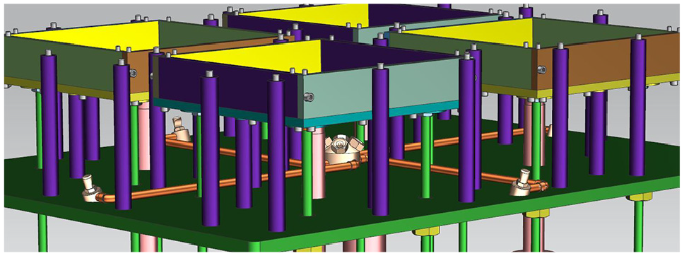
The coolant distribution system consists of a network of spray nozzles located above the rear wall and at the sides of the cavity part. The cooling manifold is attached to the feeder plate by means of suitable components (Figure 1).
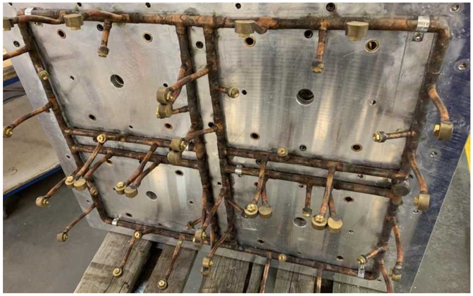
Test mold cooling manifold placed on the feeder plate.
In course of designing the basic mold assembly, some consideration is given to the possible location of the coolant distribution system or location of its components. Mold manufacturers often use nozzles with the lowest flow rate when designing the distribution system. Spray nozzles are spaced from the feeder plate closer to the cavities. The mold cannot be finished without the entire cooling system being completed first.
If the molding or the mold is cooled more than needed, the mold is supercooled, resulting in the consumption of more energy for steaming in the subsequent pressing cycle. Ideally, the mold is cooled to 80°C–70°C for polystyrene materials, and to 90°C for polypropylene materials. In fact, the temperatures given, such as the steam temperature prior to application, the temperature of the heated mold and the temperature of the cooled mold, are represented with some variation depending on the type of material. In general, the ideal mold cooling efficiency for EPS should be represented by cooling the mold surface by 40°C–50°C. 10
Another requirement for the mold cooling system is its as uniform effect on the tool or the molding as possible. This aspect affects two areas – the diversity of the molding and the pressing process area, respectively. If the cooling effect is uneven, the molding may have surface which is undesirable (Figure 2). A more negative phenomenon of non-uniform cooling is a condition where, after leaving the mold, a portion of the molding expands additionally outside the mold and deforms the final shape and dimensions of the article. In such case, the product cannot be used. The undesired expansion of the molding in the stage of its ejection may also result in the molding’s getting stuck diagonally in the cavity of the mold, or possibly getting completely destroyed. Eliminating the consequences of these errors and failures is time-consuming and disrupts the smooth running of production. The most ideal case occurs when the mold is cooled evenly on the surface only, where it comes into contact with the molding, that is, in the inner part of the mold, while maintaining the temperature of the remaining parts. If the mold, and hence the molding, is cooled to a greater extent than necessary, its volume shrinks to the appropriate shape and dimensions already in the mold. This facilitates the molding’s ejection from the mold, but at the same time the energy needed to treat the coolant is wasted.

Surface of high quality (left) and low quality (right) molding affected by the cooling system.
An adverse effect of improperly designed cooling system or of an incorrectly set water cooling cycle results in a possible greater presence of water in the molding. This is an undesirable phenomenon, since the molding must be subsequently dried. This will ultimately extend production time. For these reasons, only the amount of coolant required to achieve the desired process quality should be applied.
Requirements for the coolant are also affected by physical laws. This is the area of fluid mechanics – hydrodynamics, which also includes the process of water cooling. The sum of the flow rates of the individual spray nozzles shall be less than or equal to the flow rate designed by the pump manufacturer. If this condition is not observed, the water pressure in the system will drop and the functionality of the spray nozzles will be limited. This phenomenon can also occur due to the laminar flow of the fluid and the internal friction of the fluid, that is, viscosity. This significantly affects the coolant distribution paths and the quantity of its components. Similarly, placing the inlet manifolds at the top of the mold eliminates the aforementioned pressure drop, this time due to gravity overcoming a certain elevation. 13
It can be stated that the cooling process is a critical factor affecting the quality of the final product, not only in terms of the molding’s internal structure and strength, but also in terms of the requirements for the surface quality.
Conducted experimental measurements in the process of EPS pressing tests
The design of optimal coolant distribution for the process of pressing packaging materials made of EPS was preceded by the implementation of specific parts pressing test. A measuring circuit has been designed to obtain the appropriate temperature values during an ongoing pressing cycle. The aim was to verify the environment in which the conditions of the design and the effect of mold cooling will generally be established. The optimization of the cooling process was based on streamlining the heat removal from the mold and the product, improving the resulting molding surface quality, but also on streamlining the production of the coolant distribution system proposed, optimizing logistics processes and possibly standardizing the coolant distribution design and placement of its components using computer aid tools.
For the purpose of experimental measurements, a test mold was made for application on the HIRSH HE900 production equipment (Figure 3). Figure 3 shows the cavity plate with the part of the cavity with four nests of the test mold from the perspective of the steaming chamber. It is possible to identify the layout of the steaming openings or nozzles, by which the individual nests of the test mold differ. This view establishes the areas of the addressed water-cooling system deployment, that is, the rear side of the cavities (Figure 3(a)). Such view is not possible when the mold is assembled, as the feeder plate obstructs the view. The product itself, or the final molding, is represented by a plate shape of 250 mm × 150 mm and a thickness of 50 mm, with an internal recess (150 × 100 × 30 mm) and a label with predefined text. In order to achieve the molding’s required dimensions, the mold or the dimensions of the main mold parts are proportional to the shrinkage value given by the manufacturer of the granulated material for the pressing process. The individual mold nests differed in the quality of the surface finish and in the number of steaming nozzles (non-grinded and grinded to Ra = 3.2 µm). The possibility of not doing the grinding of the cavity surfaces, as well as the reduction of the steaming nozzles, was intended to minimize the mold manufacturing time (see Figure 3(b)).

(a) Cavity plate of the test mold – view from the steaming chamber and (b) nests of the test mold cavities.
The experimental measurement was carried out mainly to establish the design conditions of the cooling system. Two pressing tests were performed to obtain real values affecting physical quantities, and to obtain moldings for later testing and evaluation depending on the effect of the cooling process. No physical quantities were recorded during the first pressing test. Molds from this test were obtained for subsequent examination. One of the pressing cycle types was carried out under steady-state conditions with the standard setting of the conditions of the pressing device and with the standard characteristics of the test mold (standard form of coolant distribution). The second pressing cycle also took place under steady state pressing conditions, but in the complete absence of water cooling. In order to achieve the best possible cooling conditions designed for EPS, it was necessary to obtain specific values affecting physical quantities or the courses of such quantities in the second pressing test during the pressing process. One of these physical quantities, primarily affecting the process, is temperature. Therefore, in order to establish the magnitude of the temperatures acting during the process of pressing on the expanded polymers, a measuring circuit has been implemented in the test mold. It should be noted, however, that the temperature values are not the only influencing factor in establishing the mold’s cooling design conditions. Another one is the actual distribution of heat in a particular nest or in the mold as such. Contactless temperature measurements were made using FLIR T425 thermal imager to monitor the given temperature distribution. In the second pressing test, the pressing process under investigation was divided into two groups of four press cycles. Similarly, to the first pressing test, the first group of the four pressing cycles recorded ran under steady-state conditions with the standard setting of the pressing device conditions and with the standard characteristics of the test mold, but with a modified coolant distribution. This consisted of blanking the spray nozzles around the perimeter of the standard coolant distribution system of the test mold. This adjustment was implemented in a test mold to investigate the functionality of the water-cooling process with a significantly reduced number of cooling spray nozzles. The second group of pressing cycles ran similarly under steady state pressing conditions but, as in the first pressing test, in the complete absence of water cooling and with limited air cooling. Repeated restraint of cooling was not only implemented to examine the surface of the moldings, but also to obtain specific data or courses of the mold temperature values, to compare them with the pressing process under water cooling. Moldings with characteristic properties were also available from the mentioned pressing test.
In the first and second pressing test, a polystyrene granular material was used with the same chemical composition but of different grain sizes. The difference in grain size does not affect running of the tests; on the contrary, a possibility emerges to compare moldings with different material characteristics. Specifically, in the first pressing test, an expanded grain size of 2–3 mm was used and a granulate with an expanded grain size of 1.2–2 mm was used in the second pressing test.
Course of experimental measurements
After fastening the test mold into the HIRSCH HE900 pressing device and setting the standard technological parameters, an appropriate number of moldings was created to stabilize the pressing process conditions. Four pressing cycles were performed, in which the data were logged into a table on a computer using the designed measuring circuit. Each time the mold was opened, the pressing process was artificially interrupted to measure temperatures with a thermal imager. The first interruption was scheduled prior to ejection of the moldings (reading the heat distribution in the molding), and the second after the moldings’ ejection (reading the heat distribution inside the mold). A similar procedure was applied to pressing in the absence of water cooling. After forming the appropriate number of moldings and then stabilizing the pressing process conditions, four molding cycles were also done with a similar data recording as was the case in the previous measurement. Measurement conditions satisfied the standard limits – ambient air temperature approximately 20°C and slightly increased, 60% humidity. The measuring circuit was created to record the course of temperatures during the EPS pressing process. Since during the pressing process the mold is a closed whole, the temperature can only be read by contact temperature sensors. Said measurement points are indicated in Figure 4, and represent the locations of the sensors in the molding, on the molding surface and in the steaming chamber (numbers 1, 2, and 3, respectively in Figure 4). The given measurement points were selected based on the possible desired different thermal regions in the mold during the pressing process.

Location of temperature sensors in the test mold.
The measuring circuit has been designed to meet the following conditions – temperature resistance up to 160°C, resistance to increased humidity, deployment in a relatively confined space, confrontation with other mold components. Requirements in the field of measurability (fast response to temperature change, sufficient sensitivity or the value of the least measurable change, measurability of temperatures up to 160°C) were added to the above-mentioned requirements. Type K thermocouples have been used for taking the temperature. The thermocouples have a wide measuring range and, in the respective rendering, adequate resistance in harsh environments. They also respond very well to rapid temperature changes. A major disadvantage is the introduction of inaccuracies into the measurement due to conduction. The Arduino MEGA 2560 was chosen for data recording or processing. This microcontroller was used as a recording device with appropriate data transfer to a computer. Furthermore, an integrated compensation circuit and a digital signal converter in the MAX6675 microchip were used for the measuring circuit proposed.
The temperature measured on individual thermocouples is initially characterized by an analog signal in the form of a very low voltage. This voltage is transmitted to the MAX6675 integrated circuit via a thermocouple wire, that is, it is adapted by the manufacturer not to introduce inaccuracies into the measuring circuit. Subsequently, the analog thermoelectric voltage signal is converted into a digital form and fed to an Arduino MEGA 2560 device for processing and for the export to a computer database. A program for communication with the MAX6675 circuit and for exporting data to a computer has been designed for Arduino MEGA 2560. These data are recorded in the computer every 300 ms using the PLX-DAQ program.
Evaluation of the measured data
As for the definition of the measurement parameters, it is necessary to characterize the times of individual stages of the pressing cycles. For pressing in the presence of the cooling water, the filling time and steam preparation time was 8.3 s. Steaming process duration – 13 s, and cooling time 23.5 s (0.5 s cooling water, 3 s cooling air, and 20 s vacuum). For pressing in the absence of the cooling water, the filling time and steam preparation time was 7.5 s, the steaming process time was 11 s, and the cooling time was 20.75 s (shortened cooling air effect to emphasize the effect of higher temperatures 0.75 and 20 s vacuum). The total time of one pressing cycle with the application of cooling water is 57.8 s. One pressing cycle time in the absence of cooling water – 52.25 s. The differences between the individual pressing cycles are due to the absence of some activities and do not affect the evaluation as the data is synchronized to a 60 s pressing cycle due to the artificial interruption of the cycle in order to carry out the thermal imaging.
It is advantageous to use graphical representation for evaluation of the measured data. Data of temperature courses from the four pressing cycles were selected. The data, as well as the graphically represented courses of temperatures for each type of pressing in repeated cycles, were identical. Therefore, only one of the cycles is mentioned in the description.
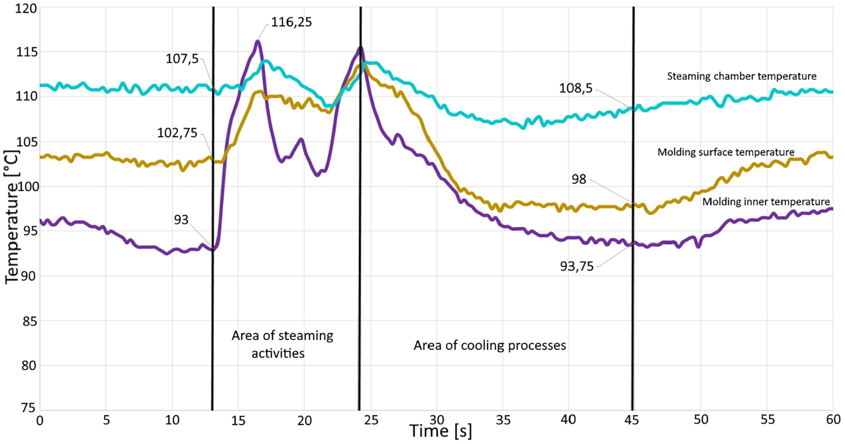
Figures 5 and 6 make it is possible to observe the course of the temperatures monitored. The waveforms show some form of noise. To ensure correct evaluation, they were not filtered. In the first stage, that is, up to the steaming area, the displacements and filling of the mold take place, together with the steam preparation. In this part, the temperatures are stable, showing the values plotted in the graphs and also in the Table 1. The values of the monitored times differ between the individual graphs according to the cycle length of the respective type of pressing. As mentioned, the courses are synchronized to a length of 60 s according to the start of the cooling process, and thus their beginnings and ends are extended by respective downtimes caused by the work of the thermal imager.

Time-dependent course of the mold temperatures measured in the presence of the water-cooling process.
Time-dependent course of the mold temperatures measured in the absence of water cooling.
Table of the measured temperature values during test pressing.

In the first stage, a slight drop in temperature inside the molding can be observed, and hence also of the mold. This is due to the filling of the mold with granular material with the aid of air, which slightly cools this part. Next is the area of application of the steaming operations, at which the mold temperature reaches its highest values. Depending on the individual steaming activities, it is possible to monitor temperature changes on the recorded temperature courses in this part. At the end of this area, the temperatures at all the points measured reach the second highest temperature value, close to the maximum.
It is not necessary to specify this area in more detail for the cooling optimization area. In the next area of action of the cooling processes, it is not possible to specify in more detail the action of the individual parts of the cooling as a function of time – the cooling water is applied over a very short time interval of 0.5 s. Thus, due to thermal inertia, that is, the thermal capacity of the material, this temperature change is not demonstrated immediately. However, this change in temperature is partially visible in the course of temperatures with a delay, of course in the case of a water-cooling process. In a test pressing with a water-cooling process present, the molding surface temperature in the cooled area drops below the temperature inside the molding. This phenomenon, when the temperature inside the molding is maintained for fusion of the polymer granules to take effect, and when the molding surface is stabilized by lowering the temperature in this area to achieve the desired surface quality, is highly desirable. It is in this part that the effects of directed water cooling can be observed. This phenomenon is also complemented by maintaining the temperature in the steaming chamber to prevent loss of steam energy to reheat part of the mold. Temperature courses are then stabilized by the action of vacuum at the temperatures indicated in the graph and shown in Table 1.
This phenomenon does not occur in the pressing process in the absence of cooling water. The temperatures are also stabilized by the action of the vacuum. Applying to both types of pressing tests, the area of cooling processes is followed by the area of side movements and molding ejection. In this part, the temperatures in the steaming chamber and on the molding surface, that is, the mold, slightly increase due to the accumulation of thermal energy in the mold materials. Conversely, the temperature from the sensor in the molding decreases, since after the molding leaves the mold, the sensor is outside the area of application of the stored thermal energy and is cooled by ambient air. This slight temperature change is then transferred to the next pressing cycle.
Figure 7 shows the courses of the temperatures measured in the pressing test with and without the water cooling process in a summary graphical representation (to better illustrate the temperature differences). Noise has been filtered out from the individual courses, which introduced inaccuracies in the temperature values. However, the graph below is not for describing temperatures but for comparing the differences. Higher temperatures can be observed at the beginning of the courses in the pressing test without the water-cooling process at all three measurement points. Next, the steaming area is identical for both types of pressing, as the achievement of maximum temperatures is followed by dissipation of heat into the environment. The cooling area is described in more detail above. Although heat is retained in the mold during the pressing process in the absence of water cooling, it has a negative effect on the molding surface.

Time-dependent course of the mold temperatures measured under the water-cooling process.
Table 1 shows the measured temperature values before and after the cooling process during both pressing tests for all four repeated cycles. Individual temperatures from repeated pressing cycles, according to the type of pressing, do not differ significantly from each other. They are abbreviated V0 to V3 for pressing with the water cooling and BV0 to BV3 for pressing without the water cooling. When comparing the temperatures between the different types of pressing tests, the values, as already mentioned, before the steaming process and after the cooling process are higher in pressing without water cooling. This difference is greatest for the temperatures at the molding surface (10°C on average) and lowest for the temperatures in the steaming chamber. For clarity, these differences are illustrated in more detail in the graphs of Figure 8. The values of the maximum temperature reached during the steaming, as mentioned, remain identical for both types of pressing. The values and graphs show that in order to achieve the desired general molding quality, it is particularly necessary to cool its surface, thus finding a compromise between lowering the molding’s surface temperature and maintaining the temperature in the steaming chamber especially due to ensuring the quality required of the technological process and minimizing the production costs. However, a greater degree of cooling is required to achieve the desired surface of the moldings.
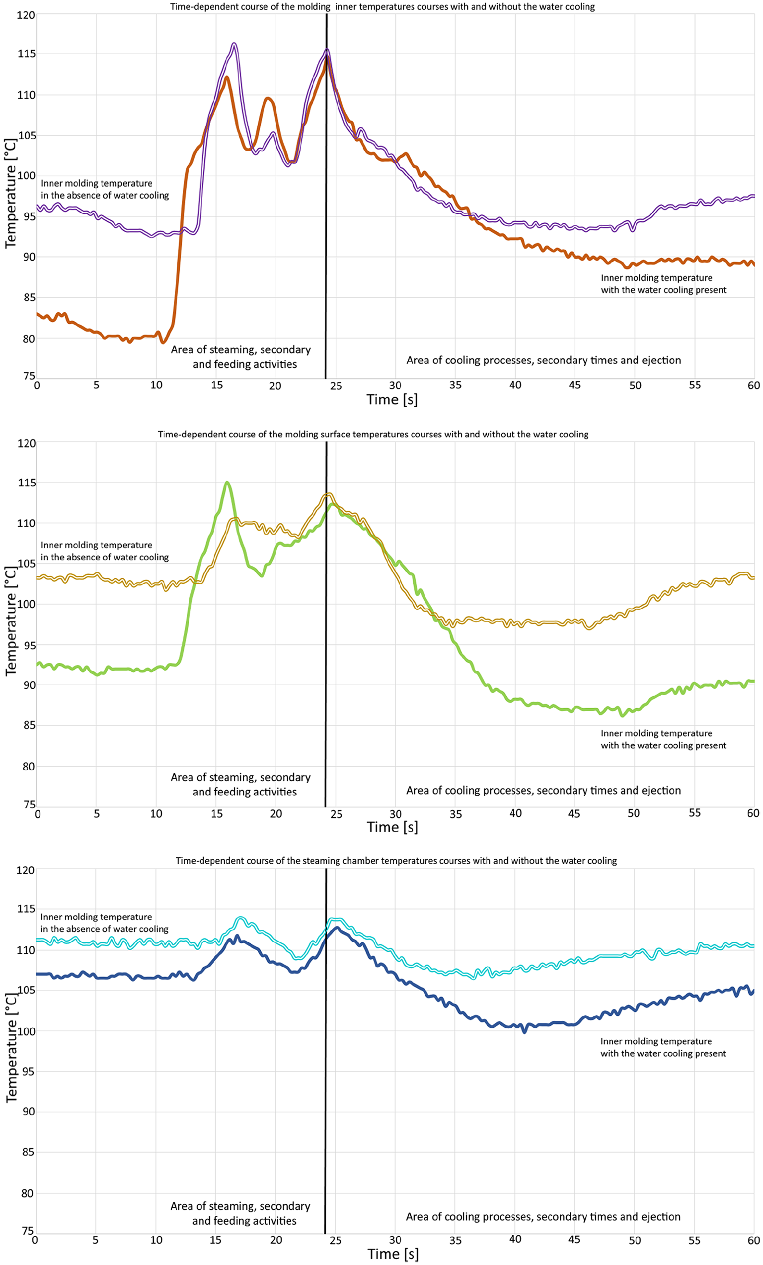
Time-dependent individual temperature courses with and without the water cooling.
Figure 9 shows the results of the temperatures measurement with a thermal imager when the process is manually interrupted. In Figure 9(a), regular heat distribution on the surface of the molding from the press cycle with the water cooling process can be observed, as opposed to the irregular heat distribution in Figure 9(b) from the press cycle without the water cooling process. The heat distribution, whether on the molding or on the mold surface, is identical for all repeated cycles. In the images it is also possible to observe a higher temperature in case of nest no. 2 (top left), which was caused by an unspecified influence of properties outside the mold and the coolant distribution system (probably due to the pressing equipment and its components used in this case). This was also reflected in the quality of moldings from this nest. To compare the molding temperatures from this reading with the values obtained from the measuring circuit, an emissivity value of 0.60 was set according to the polystyrene material tables. When comparing the temperature values, it is necessary to consider cooling the surface of the moldings due to the equalization of the temperature with the ambient air when the mold is already open. Taking into account this phenomenon, the values obtained from the thermal imager and the values obtained by measuring the heat with the measuring circuit match. It is thus possible to conclude the measurement has been correct.
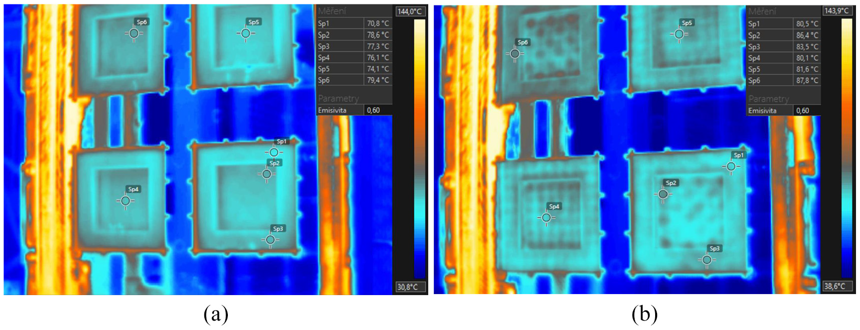
Temperature distribution on molding: (a) with water cooling process and (b) without water cooling.
Assessment of the quality of the moldings’ shape and surface from the pressing tests
At the given stage of the conducted experiment, it was necessary to assess the quality of the moldings produced, depending on the mold cooling system used. Under real conditions, the quality of moldings is assessed only by visual inspection or internal test by breaking the molding. Other types of molding testing, for example, testing of their mechanical properties, has not been done as they are not influenced by the cooling process.
All sides of the moldings from the first pressing test, that is to say under the standard design of the coolant distribution system, and in the presence of cooling water in the pressing process, have satisfactory surface. The water-cooling time in this test was 0.5 s, the time of air cooling was 3 s, and that of the vacuum was 30 s. The edges of the molding, either total or the edges copying the text on the text labels, are sufficiently accurate and clear. Labels in both dimensions are clearly legible. It is possible to observe the influence of the number and distribution of the steaming openings on the given moldings. There is a larger number of pores due to non-ventilated air concentration in the moldings from the nests with a low number of nozzles (Figure 10). On the other hand, moldings without the presence of cooling water have unsuitable, the so-called orange surface on all sides of the product. A slight difference can be observed on the upper parts of the moldings, in terms of their placement in the mold, since the respective parts have been cooled to a greater extent by the cooling air that is fed into the mold from exactly this direction. The edges of the molding are less clear cut, so the legibility of the labels is also worse.

Surface of the molding from test pressing no. 1 (40-fold magnification).
For a more detailed description of the effects of the cooling process on the molding’s surface quality, an enlarged representation of the surfaces is preferred. For this reason, the following devices were used to obtain imaging – Dino-Lite Premier AM4013MZTL Digital Output Microscopes for 40-fold magnification, and Nikon Eclipse MA100N for 100-fold magnification. Examined are the specimens of individual types of molded surfaces from pressing tests. Specifically, there are six specimens representing individual pressing tests, as well as different nesting properties of the test mold (nests with grinded and ungrinded surface). Figures 10 and 11 shows the surfaces magnified 40 times (from left to right – water cooled surface grinder, non-grinded surface, and absence of water cooling). It is not possible to visualize the grinded and non-grinded surface in the absence of water cooling, as there are considerably larger deformations on the surface due to temperatures. Between the left and the middle view, there is a small difference in the reflection of light, with the middle view displaying a greater reflection. This is due to the difference between grinded and non-grinded surfaces. In the illustrations on the right, that is, in the absence of cooling water, it is apparent that the surface of the individual grains is destroyed and corrugated by excessive heat. It is also possible to observe the effect of a smaller number of steaming openings on the molding surface, that is to say the effect of the air trapped in the mold in the process of pressing. The middle image of the molding surface in Figure 10 represents a desired surface. The individual grains have small gaps between them, and their surface is smooth. In the left image, air gaps can be observed between the grains, which can grow into deeper holes in the surface (Figure 10, image on the left – top left corner).

Surface of the molding from the pressing test no. 2 (40-fold magnification).
Figures 12 and 13 show the surfaces after 100-fold magnification (A – water cooling, grinded surface, B – water cooling, non-grinded surface, C – absence of water cooling, D – absence of water cooling, detail of the gap). Similarly, to 40-fold magnification, these images show the abovementioned differences, but with a more detailed view of the changes. Description of both the first and second pressing tests is identical and applies to these images, too. By comparing the A and B images, it is possible to observe the aforementioned reflection of light to a greater extent on a smoother surface, that is, on the surface of the non-grinded parts of the nest, where it is also possible to notice traces of the cutting tool. Image C represents unstabilized grain surface of expanded polymers, where it is evident that it is significantly damaged at the surface relative to the suitable surface of image A. Image D represents the same situation, but with a close-up image of the increasing grain gap, also due to the absence of water cooling.

Molding surface from pressing test no. 1 – 100-fold magnification: (a) water cooling, grinded surface, (b) – water cooling, non-grinded surface, (c) – absence of water cooling, (d) absence of water cooling, detail of the gap.

Molding surface from pressing test no. 2 – 100-fold magnification: (a) water cooling, grinded surface, (b) water cooling, non-grinded surface, (c) absence of water cooling, (d) absence of water cooling, detail of the gap.
Based on the analyzes performed, it can be stated that the unsatisfactory molding surface in the absence of water cooling is not caused by the absence of water on the molding’s surface, since the cooling water comes into contact with this surface only minimally through the steaming openings. It is caused by a higher mold temperature when the surface structure is disrupted. Water, or a liquid in general, is the perfect carrier of energy for cooling, since it has a more favorable kinetic energy for directing the cooling process.
Discussion of measurement results, possibilities of optimizing the mold cooling system
The results of measurements and analyzes performed make it obvious that the cooling stage of the mold for the production of expanded polystyrene by water has a critical influence on the quality of the technological process, but especially on the quality of the product produced.
The primary objective of the conducted measurements was to optimize the mold cooling system for the production of expanded polystyrene, taking into account the effective heat removal while achieving the quality requirements expected of the final product. In the field of mold cooling requirements, it is progressive to replace the original type of cooling water distribution system with a new method that changes the currently applied method of coolant distribution. One of such progressive solutions for design and implementation of EPS mold cooling distribution system is the creation of the so-called cooling water mist.
The cooling mist generates water droplets at a wide angle and space of action from its source. This mist can be created in two ways. Using finer spray nozzles or using multiple-nozzle components. The formation of a cooling mist by finer spray nozzles, that is, with smaller water droplets, is not an optimal solution for the investigated cooling area of the EPS molds. Smaller droplets have less kinetic energy, as well as less control over their direction. This is unsatisfactory in order to make the cooling process more efficient, as confirmed by the pressing tests. The loss of steam energy when the mold is reheated due to its non-directional cooling is also complemented by the potential for clogging of the nozzles with smaller openings, which would lead to the fatal failure of this cooling process.
The second way to create cooling mist while maintaining the size of water droplets and hence their kinetic energy is to use multiple spray nozzles at one location. The nature and properties of a single spray nozzle are more effective in multiple applications and create a water mist effect. However, this requires the design and manufacture of a new non-standardized nozzle body. As part of the task, a new component of the cooling system has been designed – a multi-nozzle spray head (Figure 14). The application of this type of water cooling in molds using multi-nozzle components is destined to improve all areas of the cooling distribution life cycle.

Computer model of multiple-nozzle spray head with lateral guide: (a) non-standardized nozzle body, (b) action of the multi-nozzle head with lateral guide.
From the optimization of the monitored process point of view, a possibility of a coolant distribution system with collection of water outside the steaming chamber is also interesting. The cooling system is not so much exposed to high temperatures used in steaming. Since the cooling water exposure time is short, the volume of the water sprayed is also small. In most cases it is the volume of water accumulated in the pipe. By applying the collected water outside the steaming chamber, a higher cooling efficiency is achieved in contact with the mold. This will save coolant. It is also possible to achieve an overall reduction of the pressing cycle time by correct selection of the individual cooling processes operating times. Time saving is also possible through more intense contact of water with the mold surfaces. Here, the multiple-nozzle components of the cooling system find their application or, conversely, it is possible to add the multiple-nozzle components with lateral guides to achieve even greater efficiency in contact with the mold surfaces (see Figure 15).
Implementation of a multiple-nozzle lateral guide system.
Conclusion
The measurements performed and the subsequent analysis of the data from the pressing tests were the basis for defining the conditions of the optimal design of the coolant distribution system, both in terms of efficiency of the cooling processes and minimization of the cooling stages in the pressing cycle. Using the designed measuring circuit, it was possible to monitor the temperature distribution in the EPS pressing mold. The current design of the water coolant distribution system has proved to be limiting in terms of efforts to optimize the process based on the analysis performed. The direction of the spray nozzles, together with their placement as far away from the main mold parts as possible, the spacing density depending on the efficiency of the individual nozzles, also with respect to the molding height, and the choice of larger flow rate nozzles are options without major structural modifications of the cooling system. Optimization constraints for currently applied cooling systems could be eliminated by designing a new multiple-nozzle head. This head represents the fusion of the cooling distribution system inlet and the nozzle bodies. The overall shape is a rotary body with regard to the manufacture of this component. The part passing through the feeding plate is similar to the cooling systems used up to now. A cylindrical surface of 35 mm in length with G 3/4” outer thread, which is the defining parameter of fittings, is applied for fastening to the feeding plate by resting on the inside of the plate with a widening diameter and with a locked low nut with identical thread on the outside of the plate. This part is complemented by a 46 mm blind hole passing through both parts of the G 1/2” multiple-nozzle head over a 20 mm length. A standardized quick release coupling for connection to the coolant pump hose is attached to this thread. Figure 13 shows a multiple-nozzle head along with a low nut and quick coupling in the assembly. The main part of the multiple-nozzle head has holes for four spray nozzles and four holes for lateral guides. It is a rotating element – a cylinder with a diameter of 50 mm and a length of 31 mm. At the top, this cylinder is terminated by a cone forming an angle of 35° with a height of 10.5 mm. The angle and height of the terminating cone were designed with respect to the nature of the spray nozzles. A 10 mm holes are drilled through the head at regular 90° intervals to connect the ducts to the side nozzles. A 10 mm diameter is enough to ensure sufficient flow rate. It does not significantly affect the overall dimensions of the multiple-nozzle head.
The use of nozzles with lower flow rates is inefficient. Coolant exposure time is prolonged. However, the use of nozzles with a lower operating angle and their application in a larger number and in a corresponding spacing can, while maintaining their higher flow rates, provide better range and thus a higher degree of contact with the mold parts.
Footnotes
Handling Editor: James Baldwin
Declaration of conflicting interests
The author(s) declared no potential conflicts of interest with respect to the research, authorship, and/or publication of this article.
Funding
The author(s) disclosed receipt of the following financial support for the research, authorship, and/or publication of this article: The authors thank the Ministry of Education of Slovak Republic for supporting this research by the grant VEGA 1/0051/20 (Research in field of reverse engineering deployment into diagnostics of hard to reach places).