
Abstract
The paper presents the type and dimensional synthesis of intermittent mechanisms for use in a thermoforming machine high-capacity stacking apparatus. The aim of this paper is to realize the intermittent motion of the working part of the stacker – conveyor, with a completely mechanical system that should enable the adjustment of the operating parameters of the stacker at a constant motor speed. Mechanical control ensures high positioning accuracy of the product ejection panel, as well as high repeatability of the motion cycle of the conveyor, which is key. Based on the set requirements, the concept of a planar mechanism of simple structure was chosen, which enables oscillatory movement of the output link for continuous motion of the input link, in combination with a one-way clutch (OWC). Four types of intermittent mechanisms have been proposed. However, multiple configurations of the same mechanism type can achieve the same output link motion interval, which is why 3 configurations for each mechanism type are considered, with a total of 4 output link motion intervals, which is 12 potential solutions for only one mechanism type. Afterwards, dimensional synthesis was performed for each type of mechanism by using the optimization method. Based on the analysis of the results, all of the mechanism types are potentially usable. After additional analyses, the optimal solution was chosen.
Keywords
Introduction
Plastic is an extremely important and ubiquitous material in everyday life. Its production, processing, use and recycling have a huge socio-economic significance in modern society. According to, 1 within the European Union (EU) in 2019, the highest demand for plastic came from the packaging industry, 39.6% of the total amount of plastic used, with the second highest coming from the construction industry at 20.4%. The medical field and the furniture and machine industry used 16.7%. The automotive industry used 9.6%, while a smaller part went to the electronics industry 6.2%, to domestic use and use in sports 4.1%, and only 3.4% to the agricultural sector, with the total amount of plastic used in the EU that year being 50.7 million tons. It should be noted that, in the EU in 2019 alone, the plastic industry provided jobs for over 1.56 million people and achieved a turnover of more than 350 billion EUR. The global demand for plastic is even higher, and in 2019 amounted to 368 million tons, of which 51% belonged to Asia.
Single-use cups are most often made from petroplastic, paper, or biodegradable materials. Petroplastic packaging is considered the safest for human use, even though it is made from polymers based on fossil fuels – oil or natural gas. Cups made from petroplastic are lightweight which allows for simpler and cheaper storage and transport. Furthermore, there are many technologies and facilities for processing petroplastic packaging into different useful materials. 2 Paper cups, on the other hand, contain high amounts of cellulose and have a layer of petroplastic on the inside to make them impregnable to liquids. 3 Paper cups with a petroplastic layer are easy to use and relatively cheap, but are still more expensive than purely petroplastic cups. While it is possible to recycle the paper and plastic separately, the very strong bond between the cellulose and petroplastic layers makes the recycling of paper cups both complex and expensive. 4 Due to the cost of recycling paper cups with currently available technologies, use of them is being reduced. 5 Biodegradable cups are made from polyactic acid (PLA) bioplastic – a thermoplastic polymer made by the fermentation of monomers like corn starch or cane sugar. Bioplastic cups are considered more ecologically friendly than either petroplastic or paper cups, but this has not yet been confirmed via the life-cycle assessment (LCA) method. 6 Bioplastic can only be recycled under special conditions which require a specialized recycling facility – a space which provides a temperature of 140°C and 90% humidity continuously for 10 days. Due to this, city landfills, where most single-use bioplastic ends up, are not able to process it. Aside from this, there is no evidence that supports the claim that PLA degrades faster than any type of petroplastic. 7 Another problem with the use of bioplastic packaging is the need for very large amounts of raw material. 8 A comparison of paper and petroplastic cups, as well as their respective impact on the environment, yields no clear winner. Paper cups are 2.5 times more expensive to produce than cups made from petroplastic. Furthermore, most paper cups are not recycled, but incinerated or deposited in landfills. A paper cup with a petroplastic layer takes about 150 years to decompose, about the same as plastic. As mentioned above, the plastic layer makes their recycling nearly impossible. 9 At this point in time, the most rational solution is the use of petroplastic packaging made from recycled plastic, especially when taking into consideration the production and recycling costs as well as environmental impacts.
In light of all this, it is clear that plastic will be the go-to material for a very wide range of applications in the foreseeable future. Therefore, there is merit in working to increase the efficiency of machines involved in plastic item production. This paper presents the synthesis of simple structure intermittent mechanisms meant to drive the high capacity stacking apparatus of a thermoforming machine for cup-like products. The main objective is to enable intermittent motion of the conveyor using a fully mechanical system which allows the adjustment of basic work parameters of the stacker, such as the stroke and the work coefficient. An adjustable stroke allows for flexibility and use of the stacker for a wider range of products, which increases productivity and efficiency. The work coefficient defines the time allocated for each part of the work cycle, while the total length of the cycle directly impacts the capacity of the stacker.
The paper is structured as follows. The first section explains the motivation and the objective of the research. The second section describes current state of the art in the field of intermittent motion mechanisms. The third section gives a short summary of the thermoforming process and describes the problem more fully. The fourth section presents the synthesis of different types of mechanisms which achieve oscillatory motion of the output link with continuous motion of the input link, and the analysis of their viability. The fifth section contains a summary of the paper as well as a discussion about the results. The final section states the conclusion and possible directions for future research.
State of the art
Intermittent motion mechanisms are widely used in mechanical engineering, the most widespread practical application is in semiautomatic and automatic machinery, machine tools, as well as in printing, packaging, transfer lines, etc. Intermittent motion mechanisms allow dwell periods of specified duration of output link for continuous motion of the input link. Various kinds of such mechanisms are found in existence, including ratchets, escapements, intermittent gears, star wheels, indexing cams, Geneva mechanism, 10 etc.
The Ratchet mechanism is a versatile device and is used in a large number of applications ranging from heavy-duty machinery, transmissions to fine instruments.11,12 Escapements found applications in mechanical watches, electric meters, and odometers.13,14 The intermittent gear is still another widely used indexing mechanism with the advantage of an accurate gear ratio. 15 These mechanisms all face the problem of impact loading, which can be resolved, for instance, with specially shaped teeth or by introduction of elastic elements but, nevertheless, impact will always be present to some extent, and can lead to wear, control, and stability problems.
Geneva drives are extensively used in automatic machinery and conveyors. 16 From a design point of view, Geneva is not a versatile mechanism. It can be used to produce minimum three, and usually no more than 12 dwells per revolution of the output shaft and once the number of dwells has been selected, the ratio of dwell period to motion period is fixed. Also, all Geneva mechanisms start and end with finite acceleration and deceleration. In order to solve these problems, solutions such as variable input speed, 17 curved slots 18 are proposed, all leading to more complex design.
Traditional cam mechanisms can also provide an output link with periods of dwell, but the output link must have a return stroke, which may not be always acceptable, so indexing cam mechanism have become widely used, especially in automatic machinery. Researches have been done on their geometry design,19,20 analysis,21,22 and torque balancing.23,24
Lever mechanisms have only first-order connections, which is why they can transfer significantly higher loads at higher operating speeds, and have significantly lower friction losses than Geneva and cam mechanisms. There are several approaches to the synthesis of six-link mechanisms with intermittent motion of the output link: by generating the coupling link point path,25,26 by synthesis in extreme positions,27,28 etc. However, such lever mechanisms can only produce approximate dwell. Although very small variations in the position of the output link can be achieved by synthesis, the accuracy of positioning, and repeatability of the movement are not ensured.
Most of the mechanisms that have been discussed up to this point produce intermittent motion without any assistance from other components. Some authors propose the use of complex mechanisms – combination of two types of mechanisms: Geneva and noncircular gears, 29 Geneva and epicyclic gears, 30 epicyclic and noncircular gears,31,32 etc. Those solutions can realize intermittent motion but they are complicated and expensive to design and manufacture.
So there is an actual task to develop and study mechanisms which can provide intermittent motion of the output link, which are simple, reliable, easy to design and manufacture, work without breaking the kinematic chain (no shock loads), ensure precision, and repeatability of the movement. An over-running clutch transmits torque from input to the output in one direction and free wheels or overruns (does not transmit torque) in the other direction. It, taken alone, cannot produce intermittent motion, it has to be used with additional driving mechanism. There are several design principles for unidirectional overrunning clutches: the spring clutch, frictional clutches – roller clutch and sprag clutch, and ratchet and ball clutch. The frictional overrunning clutch possesses a number of advantages, such as small size, low noise, high torque transmission, smooth connection.33–35 They are commercially available at low prices, are reliable and are, dimension-wise, similar to radial ball bearings. Generally, any type of planar mechanism with oscillating output motion can be used as driving mechanism, such as lever mechanisms, cams, gear mechanisms, pneumatic, or hydraulic cylinders.
Dimensional synthesis determines the dimensions parameters of mechanism links that achieve the prescribed task. Traditionally, linkage synthesis is divided into three types: motion generation, function generation, and path generation, each type being extensively researched and applied in practice. 36 Beside these, there are other requirements which can be essentially important for the functioning of the mechanism that can be formulated as synthesis task: mechanical advantage, 37 efficiency, 38 joint forces, 39 etc. In many cases, there will be a need for the mechanism to perform a hybrid task, that is, the mechanism has to fulfill several of synthesis types simultaneously.40,41 There are three types of methods for solving the problem of dimensional synthesis: graphical, analytical, and optimization. Graphical methods offer a quick and intuitive solution but sacrifice accuracy. Analytical methods are based on writing analytical expressions for specific positions of the mechanism. By solving them, mechanism with zero error at those positions is obtained. The main disadvantage of the analytical methods lies in the maximum number of points of accuracy that can be set. 42 Also, behavior of the mechanism cannot be guaranteed in-between. 43 Optimization methods are based on numerical methods where the solution – set of mechanism dimension parameters is found by optimizing an objective function through an iterative procedure. Local search methods have been described in.44–46 The main disadvantages of these methods are that the objective function must be differentiable and are sensitive to the initial search point. To overcome this drawback, global methods explore the solution space for a global optimum. They can also deal with geometric constraints easily. Some well-known global search methods are Genetic Algorithm, 47 Differential Evolution (DE),48,49 Particle Swarm Optimization technique, 50 and Krill Herd method. 51
Problem description
Figure 1 shows a typical machine used for thermoforming cup-like products, consisting of four stations where the following processes are conducted 52 : (i) heat-treatment of the material – heating station, (ii) forming the material with the use of molds and cooling the formed products – forming station, (iii) separation of the products from the plastic sheet with the use of blades – cutting station, and (iv) ejection of the finished products – punching station. The described processes can be done on a single station, or an array of them, depending on the design of the machine. The thermoforming process begins with the uncoiling, retraction, and heating of the foil. The motion of the foil through the machine is done periodically, where the foil motion cycle is equal to the machine production cycle time. After the foil reaches the correct temperature, it moves toward the forming station in accordance with the prescribed work cycle. After this, the mold opens and the foil moves on to the cutting station, starting another cycle. After the cutting, the foil moves to the punching station. This station is where the formed products are separated from the remaining foil – the skeleton. The forming, cutting and punching of the product can be done in a single station as well. 53 In this case, the lower part of the mold most often has an additional degree of motion – it can rotate, easing the removal of the product. The removal of the finished products is done either with pressurized air or with a mechanical puncher. Due to the high frequency of conducted cycles, an additional device is needed to stack the high number of formed products – the stacker. This device can be integrated in the thermoforming machine as a separate station or, in case there is need for a high-capacity buffer, it can be an independent machine placed at the output of the thermoforming machine.
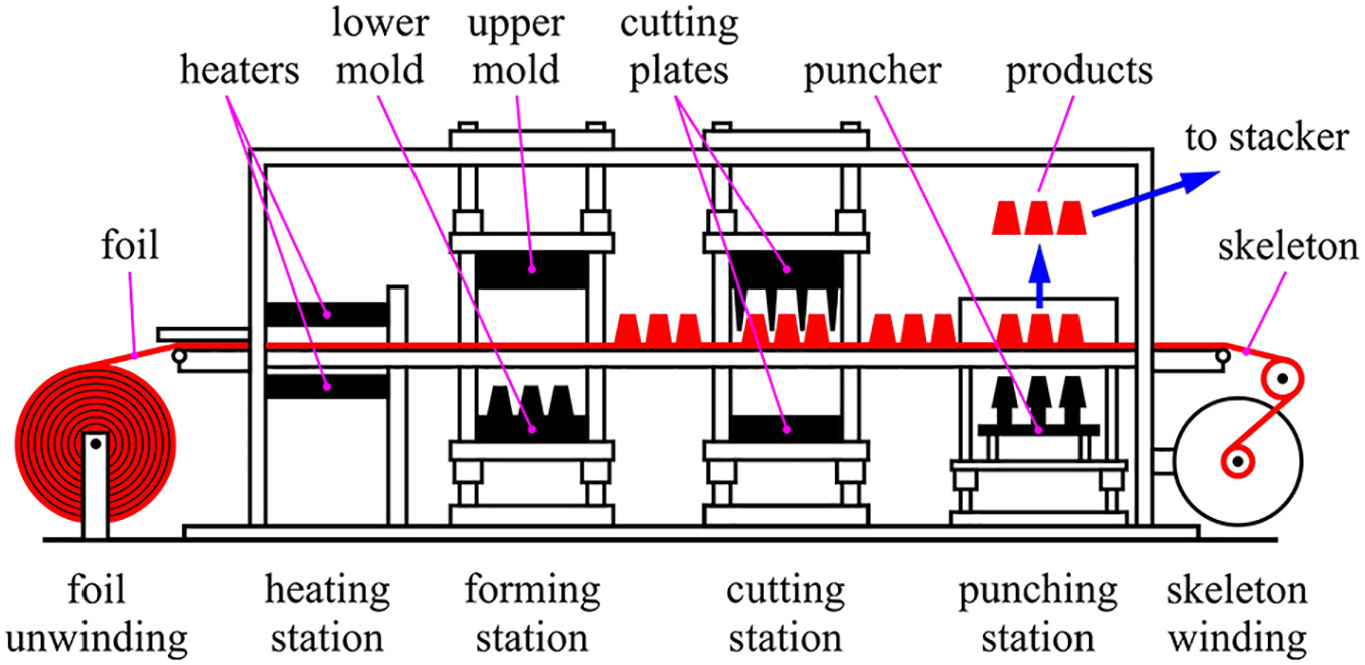
Machine for thermoforming cup-like products with four stations.
When designing the stacker, special attention should be paid to the productivity and complexity of the machine. Regardless of the level of automation, the productivity of the stacker is a key parameter, as it represents the number of products the stacker can receive from the machine and stack in the prescribed time. Fully automated stackers use grippers to remove the products from the thermoforming machine. A requirement for this type of stacker is that the motion of the gripper must be faster than the idle time of the thermoforming machine, which can be achieved in two ways. The first is to increase the speed of the gripper, which implies high accelerations that generate vibrations and dynamic impact loads. The second is to lengthen the idle time, which decreases the frequency of work cycles of the machine, lowering its productivity. If the products are removed using vacuum, and the bottom of the product is not completely flat and smooth, which is common for petroplastic packaging, the vacuum could fail to grip, leaving products in the punching station of the machine. In the case of an automated stacker without the use of grippers, an additional rotation of the lower mold plate is necessary, to ease the removal of the products. Keeping in mind that the lower mold is very large and heavy, rotating it causes very high loads which, along with the cutting force of the bladed plates dictates the dimensioning of the thermoforming machine. Therefore, introducing additional motion markedly decreases the frequency of work cycles.
An alternative to fully automated stackers with or without grippers are mechanical stackers. With a mechanical stacker, the formed products are expelled from the lower mold and are gravitationally deposited in a receptacle. 54 The stacking can also be done manually, but this is unfavorable due to contamination concerns – hazard analysis critical control points (HACCP) standard. A requirement of mechanized stacking is the orientation of the products beforehand, most often with conveyor belts or perforated panels. 55 Solutions with conveyor belts require periodic manual manipulation of the products, which makes them unfavorable. In the case of perforated panels (see Figure 2), the formed products are ejected using pressurized air onto panels which form a conveyor. The products – containers and cups, roll down the conveyor, and nest into the perforated openings of the panel. The distance between the centers of adjacent holes represents the stroke of the machine S. When the panel is positioned above the puncher, the conveyor stops. The puncher ejects the products from one panel into a buffer that is located above the machine. Afterward, the machine moves and positions the next panel above the puncher. The cycle of the stacker periodically repeats.

Schematic representation of stacker with panels.
During the ejection of the products from the holes, the conveyor should be standing still. Therefore, the conveyor’s motion must be intermittent, with periods of motion and dwell that correspond to the work cycle of the thermoforming machine. This makes the intermittent motion of the conveyor a key feature in the design of the stacker.
The aim of this paper is to offer a fully mechanical solution meant to drive the high capacity stacking apparatus of a thermoforming machine for cup-like products. Intermittent motion of the conveyor will be realized by a mechanism obtained by combining planar mechanisms with an overrunning clutch. To the best of the author’s knowledge no studies have been done to analyze and evaluate such mechanisms. This paper will focus, first, on performing type synthesis of such complex mechanisms and then, after selecting viable solutions, on their dimensional synthesis. Dimensional synthesis using Genetic Algorithm will give dimensions for the candidate designs, the properties of the feasible designs will be explored and, after that, the optimal type of mechanism will be adopted.
Synthesis of intermittent mechanisms
Any planar mechanism with one degree of freedom (DOF) can be used as the driving mechanism connected to the one-way clutch (OWC). The condition is that the input link of the mechanism performs a continuous rotation and the output link of the mechanism performs a rotational oscillatory motion. There is a large number of potential solutions. Bearing in mind that the simplicity of the constructive solution is one of the essential designing principles, in this paper the focus will be on mechanisms of simple structure. Simple gear mechanisms can produce oscillatory rotational motion if combined with a lever mechanism and epicyclic gear have to be realized as non-circular gears, so they will not be considered. Lever mechanisms with 1 DOF are formed by the Assur method 56 and if only first order connections are used they will have 4, 6, 8, and more links. In this paper, we will limit ourselves to four-link mechanisms. Two types of linkage with four links will be examined: the four-bar linkage and the quick return mechanism. The slider crank mechanism was dismissed due to its design becoming overly complicated with the introduction of the OWC. Standard OWCs are made only for rotational motion, so any solution with a slider crank mechanism would need to include an additional mechanism to transform the translational motion of the piston into rotation. Due to the complexity of such a mechanism, the slider crank mechanism was not considered as a possible solution. Following the same reasoning, cam mechanisms with translational motion followers were dismissed as well. A cam mechanism with a rotating cam and oscillating follower with a flat-face follower and a cam with a roller-follower will be explored. Since there is no need for the follower to have periods of dwell, the cam can be shaped like a circle that is eccentrically connected to the ground.
There are two main work parameters of intermittent motion mechanisms. The first is the displacement of the output link – translational or rotational, which is achieved during the period of motion. This is the most relevant parameter, as it directly defines the main functional characteristic of the stacker – the stroke S. For each mechanism, four motion intervals which they can achieve without major issues will be explored: 15°, 30°, 45°, and 60°.
The second important parameter of the mechanism is the work coefficient k. The work coefficient defines the length of time of the parts of the work cycle, which are motion period and the dwell period. While the motion period lasts, the panel of the stacker is moved into position for the ejection of the products. While the length of this period is not strictly important, it should be taken into account because the longer it is, the lower the capacity of the machine. On the other hand, the period of dwell corresponds to the ejection of the products from the perforated panel, during which the panels of the stacker stand still. It should be noted that the length of the dwell period depends directly on the time needed to complete the noted technological operation, while the total length of one cycle directly impacts the machine’s capacity. The work coefficient, for devices with one row of punchers, should have a value of around 1. Keeping in mind that different types of mechanisms cannot have identical work coefficients for the same motion interval, the work coefficient is adopted as 1 < k < 1.5.
According to Balli and Chand, 57 to ensure the proper functioning of a linkage, the pressure angle μ should be less than 45°, and for cam mechanisms less than 35°. The pressure angle is an important dynamic indicator of the mechanism’s efficiency. Analysis often features the transmission angle γ, which is complementary to the pressure angle μ, so γ should be greater than 45°.
Since all of the mechanisms are being considered for use on the same thermoforming machine, an identical distance between the fixed joints is prescribed for all the mechanisms, the value being 1 m. It should be noted that different configurations of the same type of mechanism can achieve the same motion interval of the output link. Due to this, for each type of mechanism, three different configurations will be explored: C-1, C-2, and C-3.
Four-bar linkage with OWC
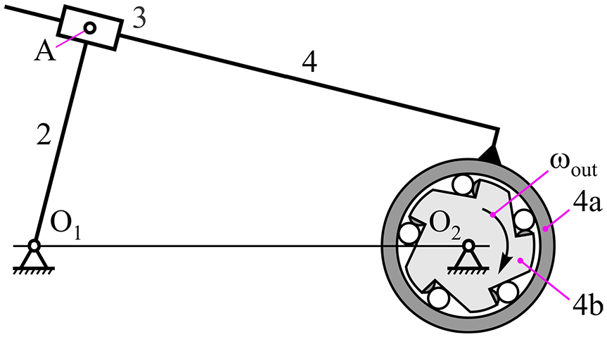
Figure 3 shows a mechanism that combines a four-bar linkage and an OWC. The four-bar linkage consists of driving link 2 – the input link, the connecting link 3, and the output link 4, which is fixed to outer ring 4a – the input link of the OWC, while the star 4b – the output link of the OWC, transmits power and motion to the driving sprocket of the conveyor.

Combination of four-bar linkage and one-way clutch.
During the work stroke of output link 4, power and motion are transmitted onto output link 4b and further to the conveyor. However, during the return stroke of link 4, the transmission will stop and output link 4b and the conveyor will remain motionless. In order to calculate the motion interval of the output link, mechanism will be presented in its limiting positions (see Figure 4).
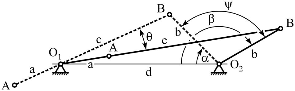
Working scheme of four-bar linkage.
The motion interval of link 4 is calculated according to the following:

with the work coefficient being:

where:

Figure 5 shows the positions of the mechanism corresponding to the value extremes of the transmission angle γ.
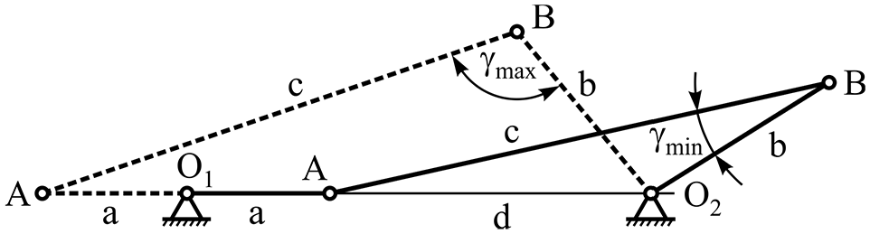
Value extremes of the transmission angle γmax and γmin.
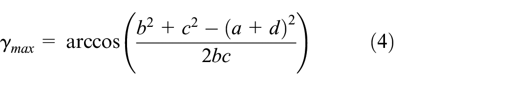
The highest and lowest values of the transmission angle are calculated according to the following:

The design parameters of the four-bar linkage are calculated so that: the motion interval of output link 4 (angle ψ) corresponds to the prescribed stroke of the conveyor – intervals ψ = 15°, 30°, 45°, and 60°, the ratio between the periods of motion and dwell corresponds to the prescribed value of the work coefficient k and that the prescribed values of the transmission angle γ are ensured. The synthesis must also include the Grashoff condition to ensure that the four-bar linkage is a crank-rocker, meaning that the output link 4 oscillates, while the input link 2 moves continuously in a full circle. Grashoff condition requires that the sum of the shortest and longest links must be less than or equal to the sum of the remaining two links:

where: lmin– the shortest link, lmax– the longest link, and ls1, ls2– middle links. Also, the input link a is the shortest, therefore a < b, a < c, and a < d.
Keeping in mind the prescribed value for the motion interval of output link 4, respective to the axis perpendicular to the axis of immobile link d, there are three possible configurations (see Figure 6): α = 180°–β for configuration C-1 (symmetrical interval), β ≤ 90° for configuration C-2 and α ≥ 90° for configuration C-3.

Configuration cases of four-bar linkage.
The synthesis is solved as an optimization problem by minimizing the objective function F(x), x∈D for the set constraints, where x = (x1, x2,…, xm) is the vector of variables, D = {x ∈ Rn|g(x) ≤ 0 h(x) = 0} is the set of solutions that fulfills the defined constraints, while g(x) ≤ 0 and h(x) = 0 are the vectors of constraints.
The link lengths a, b, and c are the parameters being optimized. Their limit values are prescribed as: 0.05 < a < 0.3, 0.3 < b < 0.6, and 0.8 < c < 1.2. The minimum value of link a is prescribed according to production requirements, the maximum values for links a and b are due to the allowed vertical dimension of the mechanism, while the values for link c are due to the allowed horizontal dimension of the mechanism. Accordingly, optimization problem is defined like:

where:


Table 1 shows the design parameters of a four-bar linkage obtained by solving the optimization problem.
Design parameters of four-bar linkage mechanism.

Values of the transmission angle γ marked with “*” are not acceptable.
According to Table 1, it is possible to achieve all of the motion intervals of link 4 (angle ψ). The work coefficient k is close to 1 for all of the motion intervals and configurations of the mechanism, which is very favorable. In the case of configuration C-3, when the motion intervals are ψ = 45° and 60°, the value of transmission angle γ is below the prescribed lower limit, making these combinations of configuration and motion intervals unusable. Furthermore, all the cases where the motion interval value is 15°, as well as all the cases for the motion interval value of 30° except the combination with C-2, the length of the input link a is under 0.1 m, which might be a problem to realize in practice. Finally, for the motion interval values of 15° and 30°, all of the configurations are potentially usable, while for the motion interval values of 45° and 60°, configurations C-1 and C-2, apart from being usable, also provide favorable lengths of the input link a. The optimization procedure, in accordance with the prescribed constraints, reported that there were no feasible solutions for configuration C-3 and ψ = 45°, as well as for C-3 and ψ = 60°, and that the problem was in the transmission angle γ. The goal was to have the insight in the trend of changing the transmission angle, so the data in the Table 1 was obtained by relaxing the conditions g3 and g4– see equations (12) and (13). So, in a situation where the load is of low intensity, configuration C-3, and ψ = 45°, could be used.
To evaluate the kinematic behavior of the mechanisms, a motion simulation of potentially usable solutions was performed in Autodesk Inventor. The input angular velocity is the same for all mechanisms. The simulations in Figure 7 show diagrams of the change of the position angle (a), angular velocity (b), and angular acceleration (c) of the output link for configuration C-1 and ψ = 15°. Figure 7 also shows that the laws of change of kinematic parameters are close to harmonic change.

Time histories of output link: (a) position angle, (b) angular velocity, and (c) angular acceleration for configuration C-1 and ψ = 15°.
The angular velocity and angular acceleration of the output link will be expressed as:


Table 1 shows the extreme values of the velocity coefficient in the working and return stroke – maxCvw and maxCvr. Since the input angular velocity is the same – the time of one cycle T remains the same, it is clear that as the interval of motion of the output link increases, the angular velocity of the output link also increases. Further, it can be noticed that, with the increase of the interval of motion of the input link, there is an increase in the difference between the extreme values of velocities – a deformation of the shape of the law of motion. The trend remains the same, but the difference between the extreme values increases. The differences between angular velocities do not exceed 15%, while between the accelerations they are very pronounced. This can be seen, for example, for the configuration C-1 and ψ = 15°, the extreme values of the acceleration coefficient are maxCa = 0.0025 and minCa = 0.002, while for configuration C-1 and ψ = 60°, they are maxCa = 0.0136 and minCa = 0.007, but the acceleration diagram remains symmetrical. However, having in mind the equation (25), the mechanism is acceptable.
Quick return mechanism with OWC
Figure 8 shows the combination of a quick return mechanism with an OWC. The quick return mechanism consists of driving link 2 – the input link, the slider 3 and the output link 4, which is fixed to outer ring 4a – the input link of the OWC, while the star 4b – the output link of the OWC, transmits power and motion to the driving sprocket of the conveyor.
Combination of quick return mechanism and one-way clutch.
Figure 9 shows the kinematic scheme of the quick return mechanism with an OWC.

Kinematic scheme of quick return mechanism and one-way clutch.
The motion interval of link 4 is calculated like:

with the work coefficient being:
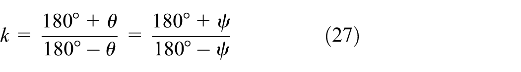
Figure 10 shows the position of the mechanism for the value extremes of transmission angle γ.

Value extremes of the transmission angle γmax and γmin.
The highest and lowest values of the transmission angle are calculated like:

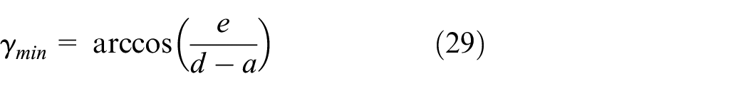
Figure 11 shows the three configurations being considered, where: e = 0 for configuration C-1, a > e for configuration C-2, and a < e for configuration C-3. To ensure that the input link 2 can complete a full rotation and that the output link 4 will oscillate, it is necessary for a < d, for a non-eccentric mechanism, and a + e < d, for an eccentric mechanism.

Configuration cases of the quick return mechanism.
Design parameters e and a, of the quick return mechanism are calculated through the synthesis process, so that the motion interval of the output link (angle ψ) corresponds to the prescribed stroke of the conveyor – motion intervals of ψ = 15°, 30°, 45°, and 60°. Furthermore, the ratio between the periods of motion and dwell of link 4 should be within the prescribed limits of the work coefficient k. The value of the transmission angle γ must also fall within the prescribed limits. The synthesis must also include the conditions that ensure the oscillatory motion of the output link 4, as well as the full circle rotation of the input link 2. Limit values of design parameters are prescribed as: 0.05 < a < 0.5 and 0 < e < 0.5. The minimum value of link a is prescribed according to production requirements, the maximum values for a and e are due to the allowed vertical dimension of the mechanism. The parameters are calculated using optimization procedure, presented in details for the four-bar linkage. Table 2 shows the resulting design parameters of the quick return mechanism.
Design parameters of the quick return mechanism.

Values of work coefficient k marked with “*” are not acceptable.
According to Table 2, it is possible to achieve all the explored motion intervals of the output link (angle ψ). The work coefficient k is directly defined by the motion interval, regardless of the configuration and dimensions of the mechanism, and since it is clear that its value is outside of the prescribed limits when the motion interval equals 45° and 60°, this makes configurations C-1, C-2, and C-3 for these two intervals unusable. By increasing the motion interval ψ, the transmission angle γ decreases, but stays within the prescribed limits. Regarding the size and practical realization requirements, the lengths of all the links are within the prescribed limits. It should be noted that the transmission angle has the most favorable value, nearly 90°, for configuration C-1 with any of the motion intervals. Finally, for the motion intervals ψ = 15° and 30°, all of the configurations are potentially usable, since they fulfill all of the prescribed requirements.
The optimization procedure, in accordance with the prescribed constraints, reported that there were no feasible solutions for configurations C-1, C-2, C-3, and ψ = 45°, 60°. Since the condition 1 < k < 1.5 is specifically related to the thermoforming process, in another case even higher values of k may be acceptable and it is important to see that this mechanism could be used with very good characteristics. Figure 12 shows diagrams of the change of position angle (a), angular velocity (b), and angular acceleration (c) of the output link for configuration C-1 and ψ = 15°.

Time histories of output link: (a) position angle, (b) angular velocity and (c) angular acceleration for configuration C-1 and ψ = 15°.
The laws of change of kinematic parameters – position and velocity, have a trend similar to harmonic change for all configurations. Since the work coefficient is significantly higher than 1, especially for greater values of ψ, there is a significant difference between the extreme values of the velocities in the working and return stroke. Also, the acceleration diagram is significantly deformed – asymmetric, although the extreme values are very close:
Cam mechanism with OWC
Within this subsection, the simplest type of cam mechanism with a rotating cam and oscillating follower will be explored. Specifically, two types: a cam with a flat-face follower and a cam with a roller-follower.
Cam mechanism with a flat-face follower and OWC
Figure 13 shows a cam mechanism with a rotating cam and oscillating follower combined with an OWC. It consists of the cam 2 – the input link, and the follower 3 – the output link which is fixed to the outer ring 3a – the input link of the OWC, and the star 3b – the output link of the OWC which transmits power and motion to the sprocket of the conveyor. Since there is no need for the follower to have periods of dwell, the cam can be shaped like a circle connected to the immobile base with a joint displaced from the center of the circle.
Combination of cam mechanism with flat-face follower and one-way clutch.
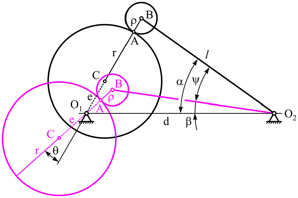
The configurations of the mechanism depend on the ratio of the design parameters: r– cam radius, e– cam eccentricity, and a– follower eccentricity. The cam radius r must always be larger than the cam eccentricity e. Possible design solutions are shown in Figure 14: a < r + e for DS-1, a > r + e for DS-2, and a = 0 for DS-3.

Design solutions of flat-face follower cam mechanism.
The motion interval of link 3 is calculated as follows:


with the work coefficient being:

The maximum value of the pressure angle μ is calculated as:


Design solutions DS-1 and DS-2 can be presented as an equivalent DS-3 mechanism. The dimensions of the equivalent DS-3 mechanism, which replaces the DS-1 mechanism, are: r1 = r–a, e1 = e, and d1 = d. This solution results in a mechanism with a smaller cam radius and larger cam eccentricity. On the other hand, the dimensions of the equivalent DS-3 mechanism, which replaces the DS-2 mechanism, are:


and d1 = d. This solution results in a mechanism with a larger cam radius and smaller cam eccentricity.
Since it has been established that both the DS-1 and DS-2 mechanisms can be reduced to an equivalent DS-3 mechanism, from here only the DS-3 type mechanism will be explored. Three configurations will be explored: e = 0.2r for configuration C-1 (small e), e = 0.5r for configuration C-2 (midium e) and e = 0.8r for configuration C-3 (large e). The design parameters e and r, of the cam mechanism are calculated, so that the motion interval of the output link 3 (angle ψ) corresponds to the prescribed stroke of the conveyor – intervals equaling ψ = 15°, 30°, 45°, and 60°. The ratio between the periods of motion and dwell should be within the prescribed values of the work coefficient k, while the highest value of the pressure angle μ must not be higher then 45°. Due to practical realization requirements of the cam, the cam radius must be less than or equal to 0.5 m, so r < 0.5. The parameters are calculated using the optimization procedure presented in detail for the four-bar linkage. Table 3 shows the design parameters of the cam mechanism.
Design parameters of flat-face follower cam mechanism.
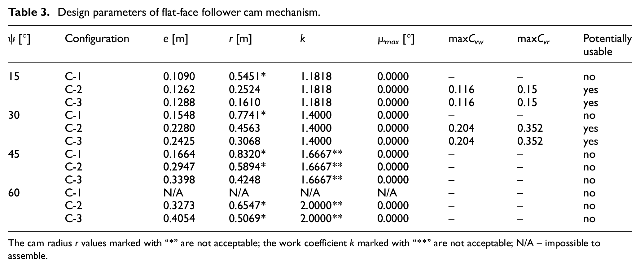
The cam radius r values marked with “*” are not acceptable; the work coefficient k marked with “**” are not acceptable; N/A – impossible to assemble.
According to Table 3, for configuration C-1 and motion interval of ψ = 60°, assembly is impossible. Due to practical realization requirements of the cam, the cam radius must be less than or equal to 0.5 m. Therefore, for motion intervals of 15° and 30°, configuration C-1 has a cam radius that is above the prescribed limit. For motion intervals of 45° and 60°, both the work coefficient k and the cam radius r, are outside the prescribed limits. Finally, for motion intervals ψ = 15° and 30°, configurations C-2 and C-3 are potentially usable, as they fulfill all of the prescribed requirements, including the values of the work coefficient k and the pressure angle μ.
As in the case of lever mechanisms, although the optimization procedure showed only four feasible solutions, in order to obtain a complete insight into the behavior of the mechanism, certain constraints were relaxed until a solution was obtained. This mechanism is extremely suitable due to the small value of the pressure angle and in cases when there are no restrictions on the dimensions and the work coefficient, it can be a good choice. Of course, with small values of the eccentricity e it is not possible to achieve large displacements of the folower – configuration C-1 and ψ = 60°.
The behavior of the kinematic parameters is the same as for the quick return mechanism, which is understandable because the quick return mechanism is a kinematically equivalent lever mechanism for a flat-face follower cam mechanism.
Cam mechanism with a roller-follower and OWC
Figure 15 shows a cam mechanism with a rotating cam and oscillating roller and follower with an OWC. The mechanism consists of the cam 2 – the input link, the roller 3 – the connecting link and the follower 4 – the output link, which is fixed to the outer ring 4a – the input link of the OWC, and finally the star 4b, which transmits power and motion to the driving sprocket of the conveyor.

Combination of cam mechanism with roller-follower and one-way clutch.
Compared to the previous mechanism, new design parameters are introduced – the radius of the roller ρ and length of the follower l. The kinematic scheme is shown on Figure 16.
Kinematic scheme of cam mechanism with roller-follower and one-way clutch.
The motion interval of link 4 is calculated as:

with the work coefficient being:

where:

Figure 17 shows the mechanism positions in which the pressure angle μ achieves its extreme values

Extreme values for pressure angle μ for cam mechanism with roller-follower and one-way clutch.
The extreme values of the pressure angle are calculated as:


Three configurations will be explored: e = 0.2r for configuration C-1 (small e), e = 0.5r for configuration C-2 (medium e) and e = 0.8r for configuration C-3 (large e). Finally, the design parameters l, e, r and ρ, of the cam mechanism are calculated so the motion interval of output link 4 (angle ψ) corresponds to the prescribed stroke of the conveyor – intervals of ψ = 15°, 30°, 45°, and 60°. The ratio between the periods of motion and dwell must be within the prescribed values of the work coefficient k, while the extreme values of the pressure angle μ must be below 30°. The practical realization of the cam and roller impose further restrictions – the radius of the cam r has to be smaller than 0.5 m, so r < 0.5, the radius of the roller ρ has to be smaller than 0.1 m, so ρ < 0.1 and the length of the arm l has to be smaller than d, so l < 1. Table 4 shows the obtained design parameters of the cam mechanism.
Design parameters of roller-follower cam mechanism.

According to Table 4, it is impossible to achieve the motion interval of the output link (angle ψ) with some of the configurations – marked as N/A. The practical realization of the cam and roller imposes further restrictions – the radii of the cam r and the roller ρ have to be smaller than 0.5 m and 0.1 m, respectively. For the motion interval of 45° with configuration C-2, the radius of the cam exceeds the prescribed maximum value, making this solution potentially unusable. For the motion interval of 30° with configurations C-2 and C-3, and the motion interval of 45° with configurations C-2 and C-3, as well as the motion interval of 60° with configuration C-3, the radius of the roller exceeds the prescribed maximum value, making all of these solutions potentially unusable. Finally, for the motion interval of 15°, all three configurations are potentially usable solutions, as they fulfill all of the prescribed requirements, including the values of the work coefficient and the pressure angle.
Figure 18 shows diagrams of the change of the position angle (a), angular velocity (b) and angular acceleration (c) of the output link for configuration C-1 and ψ = 15°.
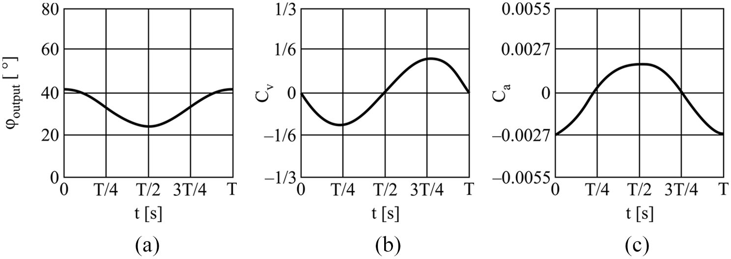
Time histories of output link: (a) position angle, (b) angular velocity and (c) angular acceleration for configuration C-1 and ψ = 15°.
Since the four-bar linkage represents a kinematically equivalent lever mechanism for the roller-follower cam mechanism, the behavior of the kinematic parameters is similar to that of the four-bar linkage. However, the deformation of the acceleration diagram is visible. As the value of the eccentricity increases, the deformation of the law of change of acceleration occurs. Configurations C-1 and ψ = 30°, 45°, and 60° (small e), and C-2 and ψ = 60° (medium e), cannot produce large displacement of the follower. As for the trend, dimensions of the cam and roller rise with the value of the follower motion interval.
Results and Discussion
The previous section analyzed the behavior of an array of simple planar mechanisms – linkages with four elements and cam mechanisms, which when combined with an OWC enable the intermittent motion of the final output link. Four types of mechanisms, and for each type three possible configurations (C-1, C-2, and C-3) that provide the same motion interval of the output link – angle ψ = 15°, 30°, 45°, and 60°: (i) four-bar linkage with OWC, (ii) quick return mechanism with OWC, (iii) cam mechanism with a flat-face follower and OWC, and (iv) cam mechanism with a roller-follower and OWC, were explored as possible solutions. According to the results, all of these mechanism types offer viable solutions, but choosing the optimal one requires further analysis. Table 5 shows the potentially usable configurations for all of the mechanism types.
Mechanism types and their configurations with respect to their potential viability: Type I – four-bar linkage with OWC, Type II – quick return mechanism with OWC, Type III – cam mechanism with flat-face follower and OWC, and Type IV – cam mechanism with roller-follower and OWC.
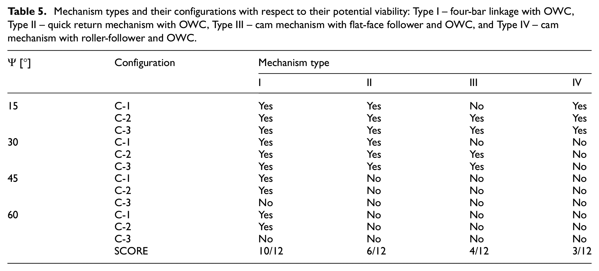
According to Table 5, types I and II have the highest number of potentially usable configurations, 10/12 (83.3%) and 6/12 (50%), respectively. On the other hand, types III and IV have less potentially usable configurations, only 4/12 (33.3%) and 3/12 (25%), respectively. However, since every configuration marked with “yes” fulfills all the prescribed requirements, meaning that it is a usable solution, other parameters need to be considered as well, like reliability, complexity, machining difficulty, assembly, weight, vibrations, cost, flexibility and kinematics, and only then can the optimal solution be chosen. Table 6 shows the scores of the four mechanism types with respect to these additional parameters.
Scores of the four mechanism types in respect of the additional features: Type I – four-bar linkage with OWC, type II – quick return mechanism with OWC, type III – cam mechanism with flat-face follower and OWC, and type IV – cam mechanism with roller-follower and OWC.

All of the mechanism types were scored and their scores compared, with the goal of selecting the most optimal solution. For every listed parameter, each mechanism type was assigned a grade, based on how favorable their characteristics were with respect to the parameter. The possible grades were a high grade (+++), a medium grade (++), or a low grade (+). Therefore, type I is the most reliable due to its simple kinematic structure – the links are easy to manufacture, and the use of standard components like ball bearings and pins increases the reliability even further. Type II is less reliable, as the reliability is largely dependent on the manufacturing quality of the slider and the guide. Type III is also less reliable, due to the existence of direct contact between two metal surfaces – the relative motion between the cam and the follower, which causes wear and other unfavorable effects, while type IV has a roller which is intended to be replaced regularly, which also lowers the reliability. Complexity refers to how complex the design is. Accordingly, type I is the simplest since it has the lowest number of parts. Types III and IV also have a low number of parts, but their geometry is more complex, which makes the design itself more complex. Finally, type II requires precise machining and assembly, which increases its complexity. Type I has the easiest machining requirements precision-wise, while types III and IV are more complicated due to requirements with regard to the kinematics and geometry of the cam, surface quality, thermal treatment, the strength and hardness of contact surfaces, etc. Type II requires precise machining of the slider and lead, meaning more passes will be required to achieve the desired results, especially along the grinded surfaces, which also increases the cost. The assembly and disassembly of type I are the simplest due to the small number of simply connected parts, while types II, III, and IV are more complicated due to their kinematic structure and part size. Type II is also very vulnerable to improper assembly, so special attention needs to be paid. Types I and II weigh significantly less than types III and IV. This is especially relevant for the cams, as due to their nature, there are variable dynamic loads. Vibrations are created when the parts are in motion, due to the existence of friction, backlash and manufacturing errors of the parts. Type I creates the least vibrations, while types III and IV produce the most. Manufacturing errors on the surface of the cams drastically exacerbate vibrations, so the cam surfaces must be adequately machined. Type II mostly produces vibrations due to assembly errors and unfavorable work conditions. According to the points made in this subsection, it was concluded that type I has the lowest cost, while types III and IV are the most expensive to realize.
An important requirement in the case of stacker design is to make the work stroke of the conveyor adjustable. This allows the stacker to be compatible with a wide array of different products, which increases both the productivity and the efficiency of the stacker. The work stroke of the conveyor is directly dependent on angle ψ, so from equations (1), (26), (30)–(32), and (39) it is obvious that the design parameters of the mechanism have to change in order to change angle ψ. In the case of linkages (type I and II) it would be necessary to change the length of the links which is technologically easily doable. In case of the flat-follower cam (type III) a new cam plate would need to be produced. The situation is somewhat better with the roller-follower cam (type IV), since, beside the cam plate, dimensions of lever, and roller can be changed.
As for kinematic behavior, all types experience similar values of velocities and accelerations. Type I, generally, has the best performance even of larger values for angle ψ. Motion laws of types II, III, and IV tend to deform with the rise of angle ψ.
According to Table 6, types I and II have the highest scores, 27/27 (100%) and 18/27 (66.7%), respectively. Type IV has 14/27 (51.8%) and type III has the score of 13/27 (48.1%), which is also the lowest score. Finally, it can be concluded that the type I mechanism is the optimal solution for the generation of intermittent motion of the conveyor.
Conclusion
This paper presents the type and dimensional synthesis of different simple structure mechanisms meant to generate the intermittent motion of a conveyor of a thermoforming machine, specifically the high capacity stacking apparatus of cup-like products. The essential requirement of the realization was that the intermittent motion of the conveyor is supplied by a completely mechanical system that allows the adjustment of basic parameters of the working elements of the stacker, such as the work stroke, at constant motor speed. Additional requirements include high productivity, a high degree of flexibility, and construction simplicity. It should be noted that all these requirements directly affected the design of the mechanical stacker, so the reception and orientation of cup-like products is done using panels, while the grouped products are ejected from the stacker using a pneumatic ejector.
Based on the set requirements, the concept combining a planar mechanism with an OWC was chosen. The planar mechanism enables the oscillatory motion of the output link, for continuous motion of the input link. Four types of planar mechanisms in combination with the OWC mechanism were proposed: (i) a four-bar linkage, (ii) a quick return mechanism, (iii) a cam mechanism with a flat-face follower, and (iv) a cam mechanism with a roller-follower. It should be noted that multiple configurations of the same mechanism type can achieve the same output link motion interval, which is why 3 specific configurations for each mechanism type were considered, with a total of 4 output link motion intervals, which is 12 potential solutions for only one mechanism type. Since four types of mechanisms were considered, the total number of potential solutions analyzed in this paper is 48. After conducting the type synthesis, the dimensional synthesis was done using the optimization method. The synthesis included the following considerations: generation of the objective function, achieving an acceptable level of mechanism efficiency – the pressure angle, meeting the set technological conditions – work coefficient, and possibility of assembly and functioning of the mechanism without defects. According to these considerations, dimensions of the candidates were determined by applying a genetic algorithm. By analyzing the results, it was determined that all of the mechanism types were potentially usable. Therefore, additional parameters were introduced, shown in Table 6, on the basis of which each type of mechanism was considered. Finally, it was concluded that the combination of a four-bar linkage and the OWC represents the optimal solution for generating the intermittent motion of the conveyor.
Furthermore, keeping in mind that an adjustable conveyor work stroke would make the stacker compatible with a wider assortment of products, thus increasing its productivity and efficiency, the second part of this research project will explore the possibility of changing the parameters of the work elements of the adopted mechanism type, as well as their adjustment.
Footnotes
Handling Editor: James Baldwin
Declaration of conflicting interests
The author(s) declared no potential conflicts of interest with respect to the research, authorship, and/or publication of this article.
Funding
The author(s) received no financial support for the research, authorship, and/or publication of this article.