
Abstract
IPMC is a new type of polymer material that will act violently to the stimulation of electrical signals. IPMC has changed the traditional mechanical driving mode. However, the development of IPMC is limited by factors like manufacture cost. In order to reduce the manufacture cost of IPMC, improve the output displacement and output force of IPMC, and make IPMC closer to real life, in this paper, we use carbon nanotubes to modify the ion exchange membrane of IPMC, and PDDA to modify carbon nanotubes and graphene. A graphite plated electrode and a carbon nanotube electrode were coated on a platinum plated IPMC. The common modified Pt-IPMC, carbon nanotubes modified Pt-IPMC, carbon nanotubes modified GS-IPMC, and carbon nanotubes modified CNT-IPMC were prepared. Through the experiment, it is found that the maximum output displacement of GS-IPMC modified by carbon nanotubes is 4.9 mm, and the maximum output force is 39 mN. The output displacement of ordinary Pt IPMC is 3.18 mm and the maximum output force is 31 mN. The maximum displacement and output force of GS-IPMC modified by CNTs are higher than those of Pt IPMC, which is more suitable for research and application.
Introduction
Ionic polymer IPMC is a new type of polymer material. IPMC is also a polymer material. IPMC is composed of ion exchange membrane and electrodes on both sides. When the electrodes on both sides are energized, the IPMC will deflect, and when an external force is applied to the IPMC, an electrical signal will be generated between the two poles. Compared with conventional actuation materials, it is endowed with the advantages of lightweight, large strain range, low energy consumption, soft structure, good environmental adaptability, strong affinity, and various functions.1–4 IPMC has very broad application prospects in the fields of biomimetic soft robots, medicine, aerospace, and underwater research. 5 For example, Bian et al. 6 have designed a bionic mechanical fish drive technology. They use pulse voltage, IPMC rapid response drive technology and spatial stacked structure drive technology to control the swing of the stacked fins of the mechanical fish to control the movement of the mechanical fish. With a length of 50 mm, a width of 7 mm, and a thickness of 1 mm, their IPMC has a maximum output displacement of close to 6 mm at the voltage of 4 V, and a deflection of more than 30°. Yang et al. 7 used IPMC to make a bionic beetle. By controlling the voltage and frequency of the IPMC wings, the action of the beetle can be controlled, and the anti-support force of the beetle wings under different frequency voltages was measured. Of the IPMC used by Yang et al., the length was 50 mm, the width is 7 mm, the thickness is 420 μm, and the maximum displacement reaches 6.4 mm under the voltage of 4.5 V. It can be seen that the output displacement is not only related to the material, but also to the size. Although the thinner ion exchange membrane of IPMC can increase the displacement, the tensile strength will be decreased.
Although the performance of IPMC is very superior and it plays an important role in many fields, in practical applications, there are still many limitations. For example, IPMC is more sensitive to water. The action will be reduced in a dry environment, 8 and the moisture content changes will also cause the deformation and instability of IPMC. In practical applications, the life of IPMC is relatively short, and will lose its activity after a certain period of movements. If the output displacement or output force of IPMC can be increased by modifications, or if the cost of production can be reduced, then IPMC will be more applicable in real life, giving IPMC a better development.9–11
Structure and driving principle of IPMC
The structure of IPMC is shown in Figure 1. IPMC has a typical sandwich structure. Its upper and lower surfaces are electrodes, and the middle part is an ion exchange membrane. In the figure, the small molecules are water molecules, the large ones are hydrated cations, and the curve is a reinforcing material. The electrode layer uses electroless plating and hot pressing methods to coat the metal on the ion exchange membrane, which is very tightly connected to the ion exchange membrane. The ion exchange membrane has selective permeability and contains a large number of water molecules inside. The ion and water molecules can move in the membrane in operation.

IPMC structure diagram.
The driving principle of IPMC is complicated. It is generally considered to be the driving principle of water and cations, in other words, it is the local expansion and contraction of the material caused by the presence and migration of cations in the polymer. It is also called the electroosmotic effect. 12 Before using, IPMC need to be fully immersed in water. The fine hydrated cations interior of the ion-exchange membrane carried with solvent molecules, move to the cathode membrane through tiny ion exchange pipe with an anionic membrane fixed to the main chain of the macro. The above conditions will cause the shrinkage of the anode area and the expansion of the cathode area, and the IPMC will bend and deform toward the anode, which is also called the anode deflection mechanism. 13 Similarly, in some Nafion membranes that was made of chitosan, cations will be fixed by hydrogen bonds and will cause cathode deflection under the van der Waals forces. 14
Normally, when the given voltage is 3 V, there will be a very large deformation. This kind of ordinary IPMC movement has a singular degree of freedom. For this reason, Nanjing University of Aeronautics and Astronautics Huo et al. 15 designed a square-pillar IPMC. This square-pillar IPMC shows good performance when driven by sine, square wave and DC voltage signals, which realizes the multi-degree-of-freedom motion of IPMC.
Reinforcing material
In the preparation of IPMC, adding reinforcing materials to the ion exchange membrane can optimize its mechanical or electrical properties. The reinforcing materials should have good compatibility with the ion exchange membrane of IPMC so that it will improve some properties with no adverse effects on other properties. 16 Commonly used reinforcing materials include carbon nanotubes, cellulose, barium carbonate, etc. Carbon nanotubes have good electrical conductivity and very good mechanical properties.
The reinforcing materials are classified as whiskers, particles, fibers, and fabrics according to their size and characteristics. The commonly used carbon nanotubes are fiber materials with relatively long length and diameter. Because of the hybrid effect among carbon atoms in the structure of the carbon nanotube, it has high mechanical strength. Compared with diamond, it has the equivalent elastic modulus, higher flexibility, higher tensile strength, extremely low density, and excellent electrical conductivity. Therefore, it has been used as a reinforcing material to be added to the ion exchange membrane of IPMC in recent years. For example, Wang 12 of Nanjing University of Aeronautics and Astronautics added single-walled carbon nanotubes to the Pt-IPMC ion exchange membrane for modification, and further modified it with water and heat, which proved an increase of output force and output displacement and a big reduction of the resistance value after modification by adding single-walled carbon nanotubes. Therefore, this article chooses to add carbon nanotubes for modification to reduce the resistance value of the IPMC and improve the mechanical properties.
Electrode layer
The electrode layer is a thin conductive layer on both sides of the ion exchange membrane, and the general electrode layer is made of precious metal, such as metallic platinum and gold. Later, researchers used highly conductive materials such as graphene, carbon nanotubes, and black scales as substitutes. These materials have excellent conductivity and are often added to other substances as conductors.17,18 The conductivity of the electrode layer and the strength of the material will affect the electrical and mechanical properties of IPMC. When the IPMC is bent, the resistance of the electrode layer will also change with the curve. 19 Sun et al. 20 Zhuangzhi of Northeast Forestry University and others prepared MCNT/MnO2 hybrid electrode IPMC using ultrasonic vibration and hot pressing methods. By changing the ratio of the two, the parameters of IPMC such as output force density, strain, and specific capacitance were improved. The average thickness of the Cu layer deposited by the Cu-IPMC is about 2 μm prepared by Yang et al. 21 The coating is uniform and smooth with the copper content of 89.94% and the silver content 8.52%. The performance of IPMC has been greatly improved and preparation time reduced. It is found that the quality of the material characteristic coating of the electrode layer has a significant impact on the performance of the mechanical properties of IPMC.
Electroless plating or hot pressing is generally used to coat the electrode layer on the surface of the film. In this article, electroless plating and electrophoretic deposition are used. Compared with the traditional electroless plating method, the electrophoretic deposition method has not only reduced half of the preparation cycle but also showed better electrical actuation performance of IPMC. 22 Before electrophoretic plating, the non-metallic materials should be modified with polydiallyl dimethyl ammonium chloride (PDDA), which is a kind of industrial wastewater precipitant. It has aromatic ring π bond in its structure, which can be conjugated with the π bond in carbon nanotubes or graphene, so that PDDA molecules are wrapped around by carbon nanotubes or graphene. Besides, PDDA molecules are strong cationic electropolymers and can form charged ion group, it is suitable for electrophoretic deposition.
Materials and methods
Experimental materials
Nafion (de520) solution with concentration of 5%, which is used for casting ion exchange membrane, was purchased from DuPont company; dimethyl sulfoxide DMSO with concentration of more than 99.5 used for accelerating membrane formation was purchased from Xilong scientific and chemical company; and NaBH4 reductant was purchased from Xiamen Haibiao Technology Co., Ltd. Industrial-grade PDDA was purchased from Suzhou Haonuo Industry and Trade Co., Ltd., which was used for package of graphene and electrophoresis of carbon nanotubes; single layer graphene and carbon nanotubes were purchased from Shenzhen Suiheng Graphene Technology Co., Ltd.; Dichlorotetra ammonium platinum was purchased from BiDe Pharmaceutical; Industrial grade methanol was purchased from Yantai Shuangshuang Chemical Co., Ltd;
Technological process
The technological process of IPMC include the casting and coarsening of membrane and the preparation of electrode, which is shown in Figure 2. The performance of IPMC is affected by the size, shape and posture of ion exchange membrane, the content of material, the selection of electrode, and the technological process of preparation. In this paper, four different kinds of IPMC were prepared by solution casting method, namely, ordinary Pt IPMC without reinforcing material, Pt IPMC with reinforcing material in membrane, GS-IPMC with reinforcing material in membrane, and CNT-IPMC with reinforcing material in membrane. The solution-casting method is to calculate the volume and mass of the required solution according to the expected film size, and then evaporate the Nafion solution into a film in the same mold. The multiple ion exchange membranes produced are roughly the same and will not affect the test.

Preparation process.
The experimental process is shown in the Figure 3 and the specific process is as follows:
Use high-temperature glass glue and test glass to make a glass mold, and dry it into shape. Measure 19 ml of Nafion solution, mix it with 1 ml of dimethyl sulfoxide and stir for 10 min with a magnetic stirrer. As the reinforcement material is added to ion exchange in the preparation, the membrane mold is slightly larger. Measure 76 ml of Nafion solution and mix it with 4 ml of dimethyl sulfoxide. Then weigh 0.16 g of carbon nanotubes with an electronic balance and add it into the solution, stir with a magnetic stirrer for 10 min, and vibrate with ultrasound for 30 min. Mix the Nafion solution and dimethyl sulfoxide evenly, and disperse the carbon nanotubes fully in the solution;
Pour the mixed solution into the mold to stand for a while and remove air bubbles. Then put the solution in a vacuum drying oven, heat and evaporate at 80°C for 20 h. During this time, the solution will gradually become viscous. Then heat up to 100°C for 3 h, then to 140°C for 30 min. Take it out and let it stand to room temperature;
Use sandpaper to polish the surface of the IPMC in the same direction. Then use dilute hydrochloric acid for 30 min to boil the polished ion exchange membrane to remove residual ions and residual impurities. Finally rinse it with deionized water for 30 min;
Take out the IPMC and wipe it dry for ion exchange. Weigh the NaOH, prepare 0.5 mol/l NaOH solution and 0.5%wt dichlorotetraammine platinum solution each with 100 ml. Soak the roughened ion exchange membrane in NaOH solution for 1 h. Then put the ion exchange membrane filled with Na+ ions into the platinum dichloride tetraammine solution for 14 h to fully react;
Take out the ion exchange membrane for a reduction plating. Weigh 1 g of dichlorotetraammine platinum and 60 ml of water and mix them fully to prepare a stable solution. Put the ion-exchanged IPMC in the solution and heat it in a water bath. When the temperature reaches 40°C, add 4 ml of NaBH4 solution and heat it up by 2°C every 10 min until it reaches 60°C. Repeat reduction plating by using the IPMC film without carbon nanotube modification and one of the modified films;
The remaining two ion exchange membranes are coated with graphene and carbon nanotubes by electrophoretic deposition. Prepare 100 ml of 1%wt PDDA solution, weigh 0.6 g of carbon nanotubes (graphene), mix and stir them for 10 min, and shake the solution for 30 min with an ultrasonic cleaner;
Centrifuge the shaken solution with a centrifuge, and mix the extracted o with methanol solution to prepare 120 ml of electrolyte. Put the electrolyte into a beaker. Clamp the reduced-plated IPMC with the cathode of the electrophoresis instrument, and the metal sheet with anode. Carry out electrophoresis at the voltage of 80 V for 15 min.

Preparation flow chart.
In the process flow, the ion exchange membrane is poured after the roughening process because as it can produce fine pits on the membrane surface, so that contact area between the film and the coating will increase and the quality of the contact surface is thus improved. Above that, it is an important method as it is helpful to improve the output performance of force and displacement. Now the roughening generally include manual polishing, machine polishing, and chemical roughening methods.21–23
The reason to do ion exchange treatment before coating the electrode by electroless plating is the ion exchange process allows the elemental metal electrode layer on the membrane surface to enter the inner part of the membrane. It can make the electrode layer and the ion exchange membrane bond more firmly so that to improve the adhesion of the electrode layer. The electroless plating layer is also denser and the hardness higher. Furthermore, the electroless plating equipment is simple and low-cost, and its thickness coating is easy to control. 23 Electroless plating is similar to ion reduction process. Generally, the reduction method is used to reduce platinum ions to metal elemental platinum so that the dense electrode layer on the surface of the ion exchange membrane can be formed.
Another function of electroless plating is to provide better adhesion points for graphene ion groups during electrophoresis with greater adhesion. During electrophoresis, due to the strong cationic properties and viscosity of PDDA, carbon nanotubes and graphene are wrapped into ionic groups, and electrophoresised them to the surface of the IPMC electrode layer of a reduction plating.
Experimental measurement
The measurement experiment of IPMC is divided into IPMC resistance test, IPMC displacement test, IPMC maximum output force test.
The electrical performance of IPMC has a very large impact on drive performance. The value of the resistance will directly affect the value of the driving force. The relationship between the parameters is too complicated to measure. When the curvature of the IPMC changes, the resistance will also change nonlinearly. Therefore, this article only measures two electrical parameters, the surface and the total resistances of IPMC.
The surface resistance is the resistance of the IPMC single layer electrode, whose value is very small. As the IPMC electrode is a thin layer covering the ion exchange membrane, the surface resistance can be seen as equal to the resistance of the thin film. The four-probe method is selected to measure the surface resistance. The four-probe method is usually used to measure small resistance with a much higher than that of an ordinary multimeter. As the four-probe method is used to measure the resistance under a very low voltage it will not deform the IPMC, making it more suitable to the research of this article. In this article, the square resistance of IPMC is first directly measured through a four-probe tester, and then the resistance R is calculated reversely according to the above formula. The schematic diagram is shown in Figure 4.

Four probe schematic diagram.
The total resistance of IPMC is the resistance between the two poles of the IPMC, which means the IPMC is regarded as a resistance connected to the circuit. The total resistance consists of four parts, including the resistance of the electrodes, the inherent resistance of the ion exchange membrane between the electrodes, the resistance of various ions, and the changed resistance after the IPMC is energized. When measuring the total resistance, in order to reduce the influence of errors, metal plates or metal electrode clamps are used to prevent the influence of excessive deformation on the resistance, and ensure that the IPMC is in good contact when it is energized.
Output displacement is an important parameter of IPMC. Under the same voltage, the greater the displacement deformation is, the better the performance of IPMC will be. This paper uses the IPMC test platform built in the laboratory to measure the action of the IPMC. The platform is shown in Figure 5. The laser displacement sensor is used to test the displacement of different IPMCs driven by a 3 V DC voltage. The IPMC will deform after being energized for a period of time, after which, it will slowly recover to a certain extent. The displacement value will be recorded every 30 s. Take the ±0.1 mm of the limit displacement as the tolerance zone, and observe the corresponding speed and duration when energized.

IPMC test platform.
Output force is also an important parameter of IPMC. The greater the output force is, the better the performance will be. Apply 2.5 V voltage to the designed IPMC, observe its cutting-edge output force, and perform comparison analysis. Due to the added carbon nanotubes, the mechanical properties of the modified IPMC produced in this article are better than that of the ordinary IPMC in theory. However, after adding carbon nanotubes, its water absorption will also change, resulting in different changes in mechanical properties. The equipment used is the dynamometer in the IPMC test platform.
Results and discussion
Surface resistance measurement
According to the experimental measurement, the resistance can be obtained, as shown in Figure 6.

IPMC resistance versus time diagram: (a) unmodified Pt-IPMC resistance changes with time, (b) modified CNT-IPMC resistance changes with time, (c) modified CS-IPMC resistance changes with time, and (d) modified Pt-IPMC resistance changes with time.
It is obviously shown that the resistances of the four IPMCs are reduced to different degrees and are close to balance. The figure also shows that the cathode and anode resistances of the four types of IPMC are different. This is because that the IPMC is placed flat at the bottom of the beaker during the electroless plating process, and the deposition is not uniform. Although the IPMC will be flipped appropriately every time when the reducing solution is added during the electroless plating process, there is a large gap between the electrodes on either side. Another reason is that the deposition of multi-arm carbon nanotubes is uneven after it is evaporated to a film, resulting in different adhesion of the electrodes on both sides and a gap of resistance.
In addition, it can be seen that the anode resistance in the four pictures all drop rapidly, but the cathode resistance drops slowly or rises somehow. It is related to the water content of IPMC. When there are many water molecules, IPMC will be softer and have a swelling effect. When the IPMC is energized, the water content of the IPMC anode drops sharply, the swelling effect is lessened, the electrode becomes tighter, and the resistance becomes smaller; However, the hydrated cations of IPMC move closer to the cathode, and the water molecules on the cathode side increase instantaneously once electrified, and the swelling effect increases, which destroys the continuity of the electrode. Therefore, the resistance drops slowly or even rises. This is particularly evident in graphene IPMC and carbon nanotube IPMC that have electrodes made through electrophoresis. This is because the electrode produced by electrophoresis in this article is not as strong as the electrode formed by reduction plating, and is easy to fall off.
Comparing Figure 6(a) with Figure 6(d), it can be found that the resistance of the modified electrode decreases. This is because the carbon nanotubes in the modified IPMC increase the adhesion of the electrode on the surface of the film, so that there are more attachment points for the electrode in ion exchange and reduction plating, so the resistance reduces; comparing three different materials, carbon nanotubes have the largest resistance, followed by graphene, and platinum electrodes. In this article, we usually use the multi-arm carbon nanotubes, which have a weaker conductivity than the other two, so a higher resistance. Secondly, as both carbon nanotubes and graphene are wrapped by PDDA, weakly conductive PDDA will be left on the electrode surface after electrophoresis. So the resistance of graphene electrode is higher than that of the platinum electrode. Other wraps or other methods for electrode preparation should be developed to reduce the resistance in future.
Total resistance measurement
The total resistance measured is shown in Table 1.
Total resistance of IPMC.

According to the data comparison of several resistance, it can be found that the resistance of the doped modified IPMC is significantly lower than that of the unmodified IPMC, which is caused by the good conductivity of multi-walled carbon nanotubes. Ion channels can be formed in the membrane which accelerates the ion transfer and reduces the membrane resistance.
The four types of IPMC electrodes produced in this article have relatively large resistances. This is because the film produced in this article is thicker than 1 mm, which has better tensile properties, but also leads to an increase in the resistance of the film. During the measurement, it was found that the graphene electrode and the carbon nanotube electrode would be larger due to the PDDA existing on the surface. Although PDDA is a kind of strong cationic polyelectrolyte, its resistance is larger than that of graphene and carbon nanotubes. After being measured and used repeatedly, part of the electrode material on the surface of the graphene electrode and the carbon nanotube electrode prepared by the electrophoretic deposition method will be detached, so that the content of graphene and carbon nanotube in the electrode will be reduced, resulting in an increase in the resistance value.
Displacement test
Perform IPMC displacement test according to the experiment introduced in materials and methods part, as shown in Figure 7, and the measurement data is shown in the Figure 8:

IPMC measurement physical map.
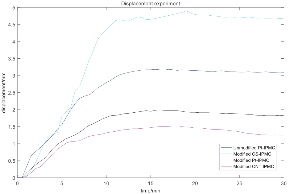
The displacement of IPMC varies with time.
In experiment, the maximum displacements of the four types of IPMC are recorded as 3.18, 4.9, 1.99, 1.5 mm; and the corresponding best lengths in use are 3.08, 4.8, 1.89, and 1.4 mm. In this way, the optimal length duration of the four types of IPMC can be compared, as shown in Table 2.
The best duration of four kinds of IPMC.
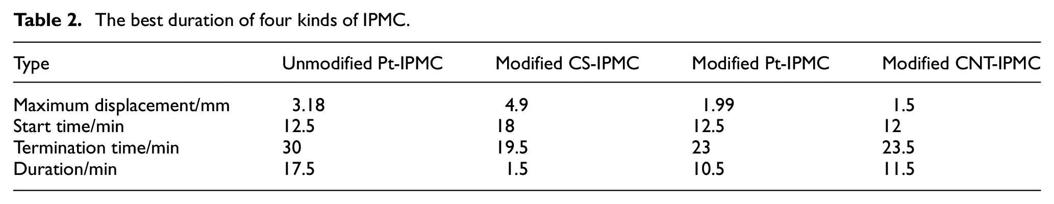
It can be clearly seen in the figure and table that the displacement effect of the IPMC using graphene as the electrode with carbon nanotubes added as the modification is much higher than that of the other three types, but the duration at the optimal length is relatively short. The three types of modified IPMC all began to rebound earlier. The reason is that ion channels will be formed during the deformation process of the IPMC doped with carbon nanotubes. According to the driving principle of hydrated cations, this ion channel will accelerate the ion movement speed in IPMC so the rebound will also happen in advance.
Comparing the IPMC of the two platinum electrodes, it is found that the output displacement of the doped multi-arm carbon nanotubes is reduced after modification, and the time of recovery goes earlier. The reason is that the performance of the multi-arm carbon nanotubes is not as good as that of the single armed carbon nanotubes. In the process of preparation, multi-armed carbon nanotubes will agglomerate. As the quality of multi-armed carbon nanotubes is greater than that of single-armed carbon nanotubes, the evaporation and film formation lasts too long. Part of the multi-armed carbon nanotubes will precipitate, resulting in uneven dispersion of carbon nanotubes in the formed film after film formation. So the effect is just fair.
The deformation at the extreme value of the graphene electrode is more delayed and the retention time is shorter. This is caused by the internal stress. When the multi-arm carbon nanotubes are not evenly dispersed, the internal materials of the IPMC will also be uneven generate internal stress. As shown in Figure 7, after the IPMC is energized, part of the IPMC will deform too fast and unstable, making the IPMC deflect to one side during the deformation process and the measured IPMC displacement curve irregular. Contrarily if the multi-arm carbon nanotubes are evenly dispersed, the actual best time of use will be longer and the limit value will be reached earlier.
Comparing the three types of modified IPMC, it is found that different electrodes have a different impact on the effect of IPMC and the graphene electrode performs much better than the other two electrodes, as it as better conductivity. After being energized for a long time, the surface resistance of the electrode is small. Furthermore the density of graphene is smaller. When preparing the electroplating solution, the volume of the 0.3 g of graphene is much larger than the volume of the 0.3 g of multi-arm carbon nanotubes. The graphene in the ion group wrapped by PDDA wrapping will be high, so the quality of ion cluster formed and the electrode quality will be better after electrophoresis.
In summary, the displacement capacity of modified GS-IPMC is far beyond that of ordinary unmodified IPMC.
Output force of IPMC
The output force of IPMC changes with time as shown in Figure 9.

Force versus time diagram.
According to the figure, it can be seen that the output force of the graphene electrode IPMC is much greater than that of the other three types of IPMC. The output forces of the four types of IPMCs all increase at first and then decrease as is expected. The mechanical changes of these IPMCs are also similar to the changes of displacement. The IPMC doped with carbon nanotubes obviously reached the extreme point earlier and rebounded earlier. This is because carbon nanotubes create new channels for ion movement. When energized, water and cations move through the ion channels, shortening the time for IPMC to reach the maximum output force. Similarly, the recovery from the deformation is faster during rebounding. The output force retention time is also longer when the platinum electrode of the IPMC is not modified, which is also consistent with the displacement.
Through comparison, it can be concluded that the output of the three types of IPMC force differ greatly, which proves that different electrodes has great influence on the force. The IPMC of the graphene electrode drops too fast is related to the early breakdown of the ion exchange membrane due to the excellent conductivity. And thus the rebound is very rapid. However, the platinum electrode modified IPMC is relatively small in terms of displacement and mechanical output. It is related to the uneven dispersion of multi-arm carbon nanotubes during the preparation of IPMC. A small amount of multi-arm carbon Nanotubes will cause the decline of performance of the film. When the electrode layer is plated, multiple electroless plating is used, which is different from the other two kinds of IPMC. The IPMC made in this article is shorter and thicker. As size of the IPMC will greatly influence the performance, under the above circumstances, the gap in mechanical properties becomes more obvious.
Conclusion
In this paper, four different types of IPMC are produced: graphene electrode modified IPMC, carbon nanotube electrode modified IPMC, platinum electrode modified IPMC, and ordinary unmodified platinum electrode IPMC. The four IPMCs are compared by different experiments. The results show that, the deformation trend of the four IPMCs is the same, but the displacement performance is different, and the performance of the carbon nanotube IPMC modified by the graphene electrode has been improved.
In the experiment, the maximum displacements of the four IPMCs were 3.18, 4.9, 1.99, and 1.5 mm respectively, and the maximum output forces were 39, 19, 7, and 26 mN respectively. And the maximum displacement reached 4.9 mm, which is 1.54 times more than that of the ordinary platinum electrode IPMC. In the cutting-edge experiment of output force, the maximum output force of CS-IPMC is 39 mN, which is 1.25 times more than that of the ordinary platinum electrode IPMC. The results show that the performance of CS-IPMC is much better than that of Pt-IPMC.
In the resistance experiment, the resistance value of CS IPMC is also less than that of ordinary Pt IPMC. The total resistance of CS IPMC and Pt IPMC is 1124 and 1443 Ω respectively. The data show that the total resistance of CS-IPMC is much less than that of Pt-IPMC. This is also one reason why CS-IPMC has better mechanical properties. The initial surface resistance of CS-IPMC is 113 Ω and that of Pt-IPMC is 112 Ω. The surface resistance of the graphene electrode IPMC is also close to that of the platinum electrode IPMC, The reason is that the graphene has good conductivity and the multi-walled carbon nanotubes are added to the film to form ion channels, which further improves the performance of IPMC.
However, in the experiment, the quality of the multi-armed carbon nanotubes is poor and the mass is relatively large so the multi-armed carbon cannot be suspended in Nafion solution. Although ultrasonic vibration is used, stratified precipitation is rapidly generated during mold making, resulting in uneven distribution of reinforcing materials in the membrane, and reduced material properties to varying degrees. Comparing the four types of IPMCs produced in this article, the prices of graphene as the electrode material and multi-walled carbon nanotubes as the reinforcing material are much lower than that of platinum-plated materials. The cost performance of graphene electrode IPMC is higher than that of platinum electrode IPMC. Its maximum output power and output displacement also exceed the commonly used platinum electrode IPMC which means it is not only much faster, but also can greatly reduce the preparation price and ensure a similar performance.
In the experiment of this article, there are some prominent problems that need to be solved,
The uneven dispersion of reinforcing materials in the film;
Stress problem still exists after film formation;
The stress in the film increases after electrophoretic deposition;
The uneven deformation of the prepared IPMC.
The above problems need to be optimized with new preparation methods to make IPMC more applicable to experiments and real life. In following work, in order to improve the performance of IPMC, better film preparation methods, electrode preparation methods, and better materials can be applied to further modify IPMC, so that the reinforcing material can be evenly dispersed inside and the stress be reduced after coating.
Footnotes
Handling Editor: James Baldwin
Declaration of conflicting interests
The author(s) declared no potential conflicts of interest with respect to the research, authorship, and/or publication of this article.
Funding
The author(s) disclosed receipt of the following financial support for the research, authorship, and/or publication of this article: 1. Heilongjiang Provincial Natural Science Foundation of China (LH2020E089): Controllable synthesis of aligned silver nanowire arrays and its effect on the mechanical and electrical properties of IPMC. 2. China Postdoctoral Science Foundation (2021M691970).