
Abstract
A proper criterion to guide how to determine the cross-section diameter of non-standard large-sized O-rings used in deep-ocean pressure chambers (DOPCs) is absent. To design a large-sized O-ring only by scale-up could be a lack of persuasiveness, and it will probably cause the increase of cost. This paper gives a detailed study on the static sealing performance of O-rings by finite element analysis (FEA). The results show that the influence of the inside diameter of O-rings can be ignored, and the O-rings with a large cross-section diameter may not be applicable to the high-pressure DOPCs, but it can allow a larger sealing clearance to be used in the low-pressure DOPCs. The reference values of safe sealing pressure with different cross-section diameters and different sealing clearances are ascertained. An improved criterion to guide how to determine the cross-section diameter of non-standard large-sized O-rings used in DOPCs is proposed. The results obtained in this paper can provide a more convincing guideline for the O-ring sealing design not only in DOPCs but also in the similar pressure vessels.
Keywords
Introduction
Pressure testing with a deep-ocean simulation system (DOSS) is required by all leading classification societies worldwide to ascertain the quality of design and fabrication of submersibles. It is an ideal means to validate the safe use of deep-ocean equipment and is a vital tool to check whether the pressure structure is safe and reliable. The major component of a DOSS is a deep-ocean pressure chamber (DOPC), whose sealing design is a challenging task due to the large size of sealing surfaces and the high sealing pressure.1,2
The sealing type of DOPCs is generally static, because there is no relative motion between seals and sealing surfaces when pressure chambers are in operation. The most common static seal used in DOPCs is the elastomer O-ring, because it has a simple structure with light weight, and is convenient to be replaced when it is aging or deteriorated. The test results show that the limit for pressure level of O-rings can be up to 350 MPa, which can meet the needs of the pressure testing with a DOSS.2,3 Figure 1 shows a common O-ring sealing design used in many DOPCs.4–8
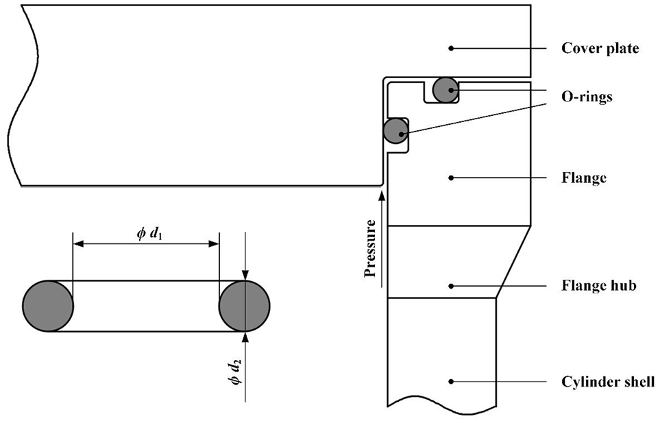
Schematic of a common O-ring sealing design in DOPCs.
The O-rings used in DOPCs usually have a large inside diameter d1 and a large cross-section diameter d2, which are both non-standard sizes. However, there is little research about how to determine the cross-section diameter of an O-ring used in DOPCs based on the sealing pressure (or working pressure) P and the sealing clearance C. In the practical engineering application, such designs are usually dependent on designer’s engineering experience.
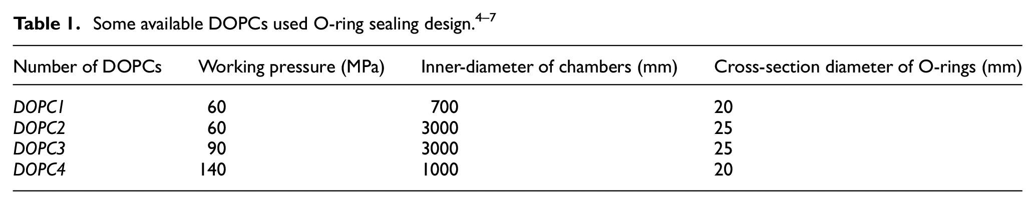
Zhou et al. 4 designed a DOPC with 60-MPa pressure, wherein the cross-section diameter of the O-rings is 20 mm. Huang et al. 5 also designed a DOPC with 60-MPa pressure, wherein the cross-section diameter is 25 mm. Bian et al. 6 developed the 930 Pressure Chamber with 90-MPa pressure for the China Ship Scientific Research Center (CSSRC) of the China State Shipbuilding Corporation (CSSC) Ltd., and the cross-section diameter of the O-rings is also 25 mm. What’s more, the Hadal Science and Technology Research Center (HAST) of Shanghai Ocean University designed a DOPC with 140-MPa pressure, and the cross-section diameter of the O-rings is just 20 mm. 7 The related information of these four numbered DOPCs is summarized in Table 1.
Even with the same sealing structures, the determination of the cross-section diameter of the O-rings used in above-mentioned DOPCs does not comply with a specific criterion. The cross-section diameter of the O-rings used in the DOPC1 was determined by the proportion of the recommended sizes in dynamic sealing application, 4 but the O-rings with d2 = 20 mm can also be used under the condition of P = 140 MPa, which was verified by the DOPC4 with a larger inner-diameter. 7 The cross-section diameter of the O-ring used in the DOPC2 was enlarged to 25 mm for the larger inner-diameter, 5 but the O-rings with d2 = 25 mm can also be used under the condition of P = 90 MPa pressure, which was verified by the DOPC3 with the same inner-diameter. 6
The authors suggest that to design non-standard large-sized O-rings only by scale-up could be a lack of persuasiveness or verification, and it will probably cause the increase of cost and a waste of materials. This should be paid more attention to, because a small increase in the cross-section diameter of a large-sized O-ring can lead to a large increase in cost. The reference values of safe sealing pressure of O-rings used in DOPCs should be determined, which may be influenced by the cross-section diameter and the sealing clearance of O-rings. A proper criterion to evaluate the static sealing performance of large-sized O-rings should also be clarified.
For this purpose, the present paper aims to give a detailed study on the static sealing performance of large-sized O-rings used in DOPCs by finite element (FE) method since experimental verification is too high cost to be arranged. Following this introduction, the basic theory and methodology will be introduced, including the automatic sealing mechanism of elastomer and the Mooney-Rivlin (MR) hyper-elastic theory. Then, a FE model of O-ring static sealing based on ANSYS platform will be presented, and the stresses and the strains of the O-ring will be analyzed. On this foundation, the effects of the cross-section diameters of O-rings and the sealing clearance will be discussed, and the reference values of safe sealing pressure with different cross-section diameters and different sealing clearances will be ascertained. Finally, some conclusions will be drawn, which could provide some valuable basis to the sealing design of DOPCs in marine engineering as well as to the similar pressure vessels.
Basic theory and methodology
Automatic sealing mechanism
An elastomer O-ring has the characteristic of automatic sealing mechanism. As is depicted in Figure 2(a), the O-ring with its free condition, is assembled in the sealing housing initially. During the assembly, the O-ring is compressed by an amount of Δd, and then, the sealing surfaces (or the contact surfaces) are subjected to a pre-load, and an initial contact stress σ0 is produced, which is illustrated in Figure 2(b). Generally, due to the compression ratio c (defined by c = Δd/d2) and the tolerance of components, there leaves a sealing clearance C between two sealing surfaces. In operation, the sealing pressure P acts upon one side of the O-ring, shown in Figure 2(c). And then, the contact stress increases from σ0 to σp, and we have a simple approximate relation as follows 9 :

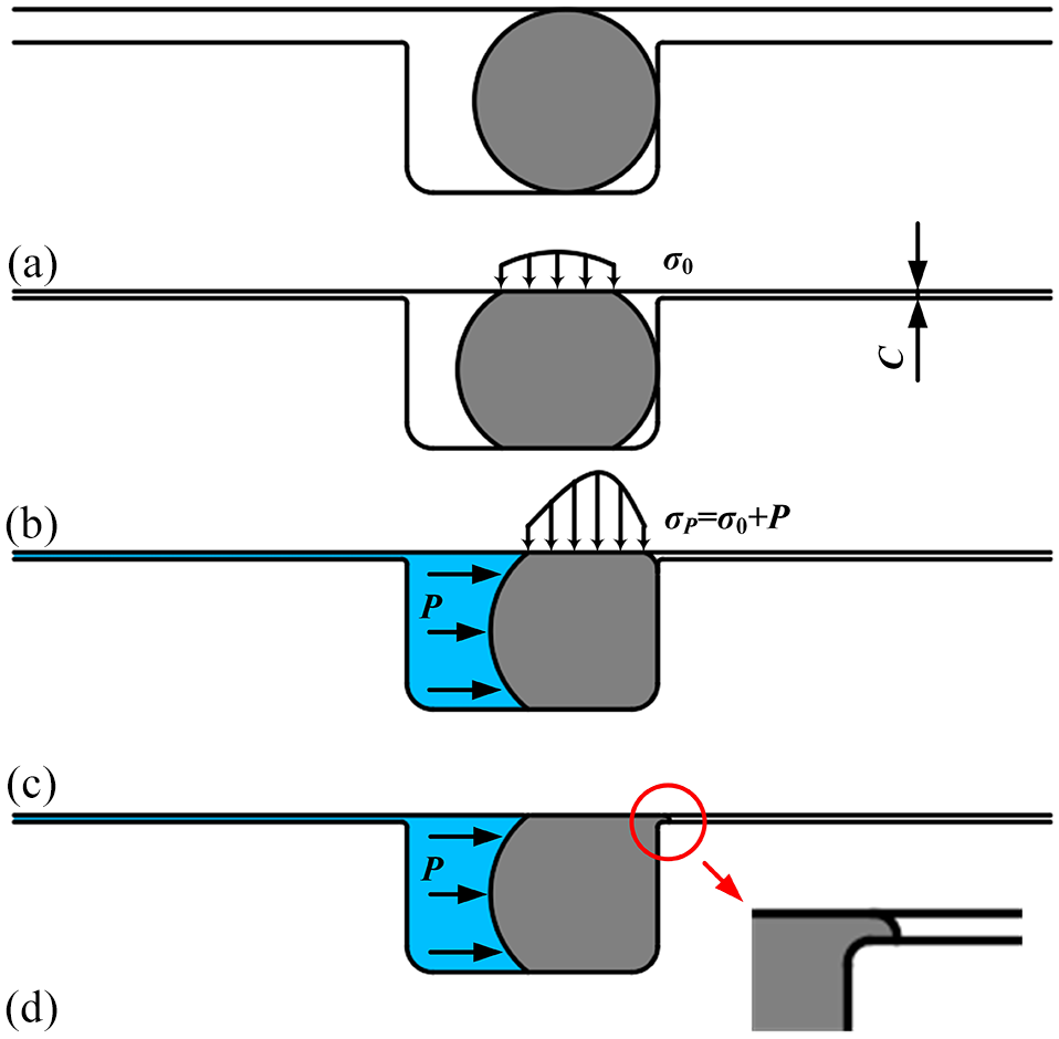
Schematic of sealing mechanism of elastomer O-rings: (a) free condition before assembly, (b) after assembly, (c) working condition, and (d) extrusion.
Equation (1) means that the contact stress σp is always higher than the sealing pressure P with the amount of the initial contact stress σ0 that is determined by the sealing clearance C. However, if the sealing pressure P is too high, a portion of the O-ring could be squeezed into the clearance between two sealing surfaces, which is called extrusion, as is shown in Figure 2(d).3,10 The automatic sealing mechanism is an important criterion to judge the sealing failure of an O-ring in engineering and FEA, which can be called the Stress Criterion.
Mooney-Rivlin model
The elastomer material presents a very complicated hyper-elastic behavior, which exceeds the linear elastic theory. Thus, several constitutive theories based on the strain energy W have been proposed. 11 Among them, the Mooney-Rivlin (M-R) model may be the most popular hyper-elastic material model used in FEA, which can be expressed as follows12,13:

where Cij is the material constants (C00 = 0), I1 and I2 are the invariants of principal extension ratios, and n is the number of order (n = 1, 2, 3). Two invariants I1 and I2 are given by12,13

where λ1, λ2, and λ3 are three principal extension ratios, and λ1λ2λ3 = 1. The material constants Cij represent inherent properties of materials, which can be obtained from the uniaxial tension or compression test experiments. Here, λ1 = λ, λ2 = λ3 = λ−1/2, and then, the invariants I1 and I2 become12,13

Methodology
The full-ocean-depth (FOD) pressure is about 115 MPa, and the maximum test pressure of DOPCs could be from 1.1 to 1.5 times of the FOD pressure. 2 Thus, the boundary condition of sealing pressure in FEA ranges from 10 to 200 MPa with 10-MPa increment in this paper.
Then, according to the regular patterns of standard sizes of O-rings, the cross-section diameters of 6.99, 9.52, 12.7, 19.05, and 25.4 mm are used for FEA in this paper. As is shown in Table 2, the authors found that the nominal cross-section diameter and the corresponding tolerance of O-rings in inch can be expressed in the form of sequences dN and tN, and the formulas of the general terms are presented in equations (5) and (6).


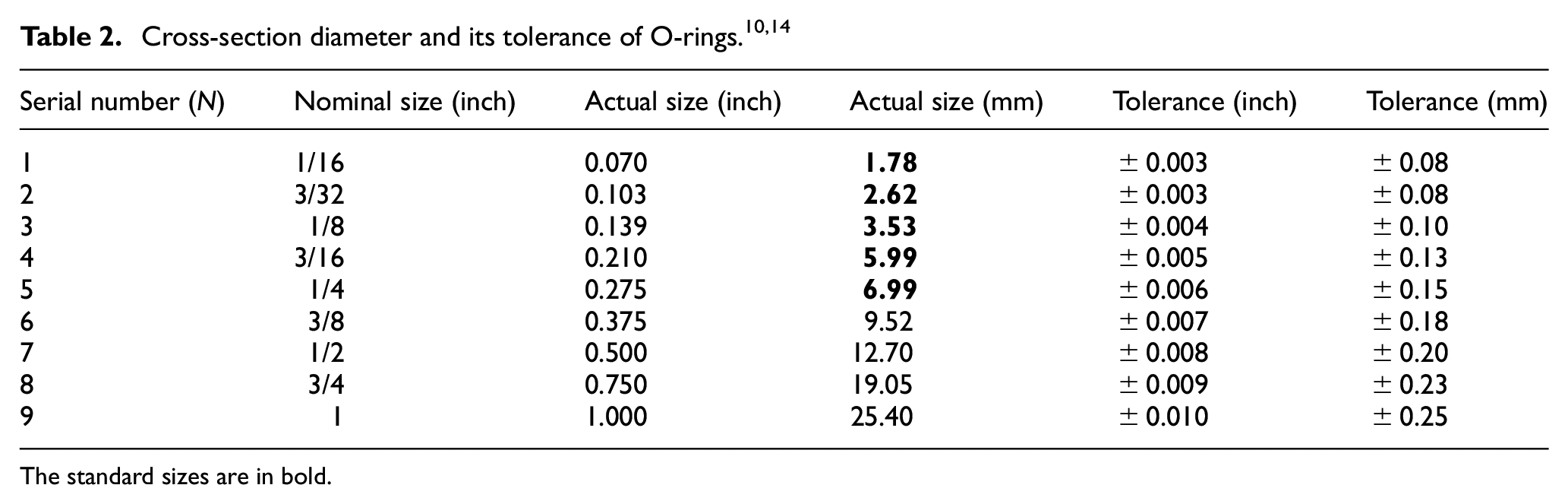
The standard sizes are in bold.
Moreover, with the errors of numerical computation by using commercial software and the limitation of hyper-elastic theory, the data obtained from FEA must be analyzed properly. First, the Stress Criterion suggests that there is an approximate linear relationship between the contact stress and the sealing pressure P. With the sealing clearance C decreasing, the contact stress must be increased under the same condition, and vice versa. Thus, if the results of FEA are against the Stress Criterion, the corresponding situation can be regarded as a danger for engineering design. Meanwhile, from another perspective, it can help to ascertain the safe sealing pressure PS and the allowable maximum sealing clearance Cmax. Second, apart from the Stress Criterion, another sealing criterion of sealing performance in FEA is the Strain Criterion. Baumann 13 proposed that the sealing performance of O-rings can be accepted if the maximum strain is below 1.0. The authors evaluate the maximum strain of the O-ring used in the DOPCs listed in Table 1 by the equivalent FE models, and it is necessary to show a result here in advance, that is the maximum equivalent strains of the O-rings are all below 0.67. Compared to the Baumann’s Criterion, it means a safety factor of 1.5, conservatively. Therefore, the authors proposed an improved Strain Criterion, that is the maximum equivalent strains of the O-rings should be below 0.67 in FEA. Because the above-mentioned DOPCs work well for many years, the improved Strain Criterion is more convincing. In this paper, to ensure the reliability of the results obtained from FEA, the static sealing performance of O-rings will be evaluated by the combination of the Stress Criterion and the improved Strain Criterion.
Finite element analysis
Finite element model
Due to the axial symmetry of structure, a two-dimensional (2D) FE model of O-ring static sealing is carried out based on ANSYS platform, see Figure 3(a), wherein d2 = 6.99 mm. The sizes of the housing are determined according to the Parker O-ring Handbook and International Organization for Standardization (ISO) code.10,15 Here, the compression ratio is about 18% and the housing fill is about 70%.
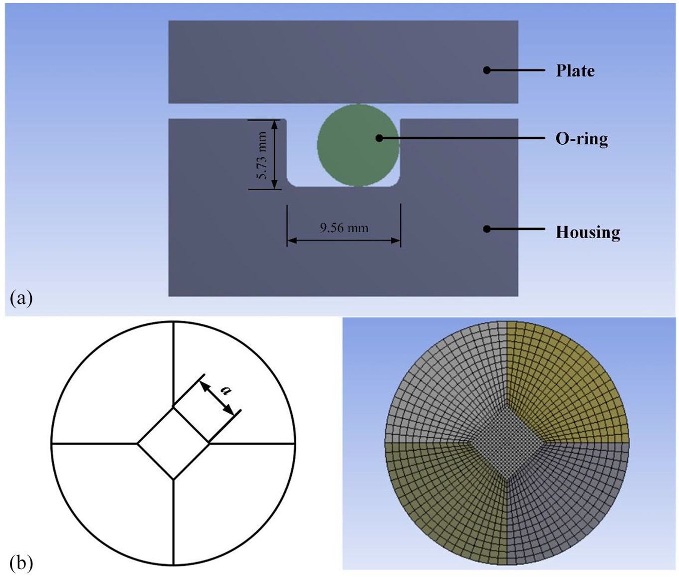
(a) Schematic of O-ring static sealing in FE model and (b) meshing of O-ring with the “ancient coin” method.
To obtain the elements of the O-ring with better quality, the “Ancient Coin” method is used in meshing, which is depicted in Figure 3(b). The dimension of “square-hole” in the center of “ancient coin”a should be determined by equation (7) to decrease the aspect ratio of grids. The authors find that the element quality of the O-ring can reach a superior level in ANSYS platform when the element size of “square-hole”a is half of the other portion’s size. Here, a is 0.1 mm, and the “Element Quality” (one of mesh metric in ANSYS, 16 the closer the value is to 1, the better the quality of elements) is about 0.995.

The materials of the plate and the housing are assumed to be structural steel. The elastomer of the O-ring is selected as Nitrile Butadiene Rubber (NBR) which is a common material of O-rings used in DOPCs. The M-R model parameters were obtained by uniaxial tension and compression tests accomplished by Zhang et al. 17 In this paper, three-order M-R model is used to increase the accuracy of FEA, and the material constants are given in Table 3.
Material constants of three-order M-R model. 17

Frictional contacts are set in FE model. The non-linear contact algorithm is augmented Lagrange which is basically the penalty method with additional penetration control, and the pressure and frictional stresses are augmented during the equilibrium iterations in such a way that the penetration is reduced gradually. The augmented Lagrange algorithm can be described by equation (8). 18

where Kn is the normal contact stiffness, un is contact gap size, λi+1 represents the Lagrange multiplier force at iteration i + 1, and 18
where τ i is the tangential contact stress at iteration i, and ε is the compatibility tolerance which can be defined by users.
After acting boundary conditions, including the sealing pressure P and the sealing clearance C (controlled by displacement), related results can be obtained by solving the FE model.
Effect of frictional coefficient and inside diameter
Frictional coefficient has a great effect on the convergence of nonlinear FEA, which is generally taken as 0.05–0.20.19,20 However, the frictional coefficient between rubber and steel is usually 0.5 without lubrication. 21 Thus, it is necessary to determine a proper frictional coefficient in FEA.
Moreover, the inside diameter of O-rings is an important factor in dynamic application, which can range from 500 to 3000 mm in DOPCs. 2 Therefore, it is necessary to clarify whether the inside diameter of O-rings can affect the static sealing performance or not.
The changes of the stresses and the strains of the O-ring along with the frictional coefficient and the inside diameter are investigated (see Figures 4 and 5). The results are shown as follows:
The changes of the contact stress along with the frictional coefficient are very small, and the equivalent stress and strain are increased slightly with the frictional coefficient increasing. Thus, frictional coefficient ranging from 0.1 to 0.5 can be used in FEA according to the practical lubrication condition. In the following analyses, the frictional coefficient is set to be 0.5.
The stresses of the O-rings are decreased slightly with the inside diameter of the O-rings increasing, but these small changes can be ignored. The results are in accord with the fact that the inside diameter of O-rings is not specified in ISO codes. 14 In the following analyses, the inside diameter is set to be 3000 mm.

Changes of stresses and strains of O-ring along with frictional coefficient.
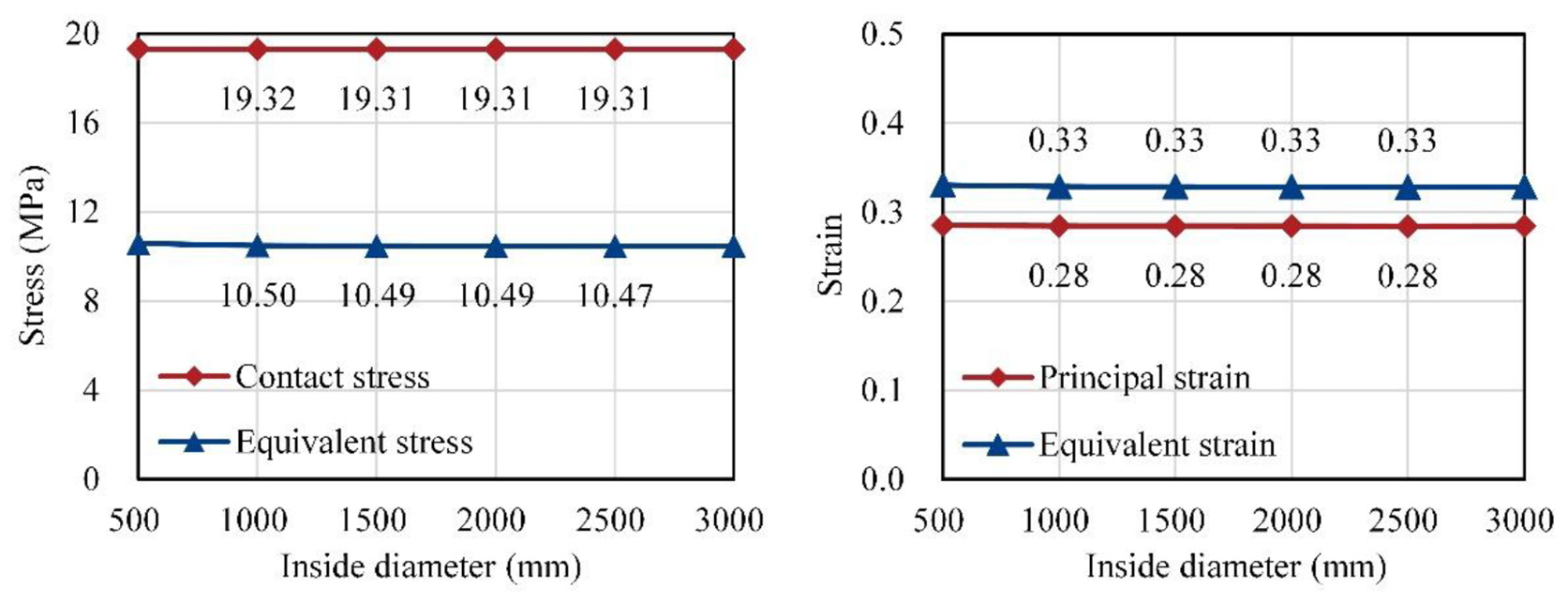
Changes of stresses and strains of O-rings along with inside diameter.
Stress analysis
The changes of the contact stress and the equivalent stress of the O-ring along with the sealing pressure, and the effect of the sealing clearance are investigated (see Figure 6). Some representative cloud pictures of contact stress of the O-ring are shown in Figure 7, from which the extrusion of the O-ring can be observed in some cases.
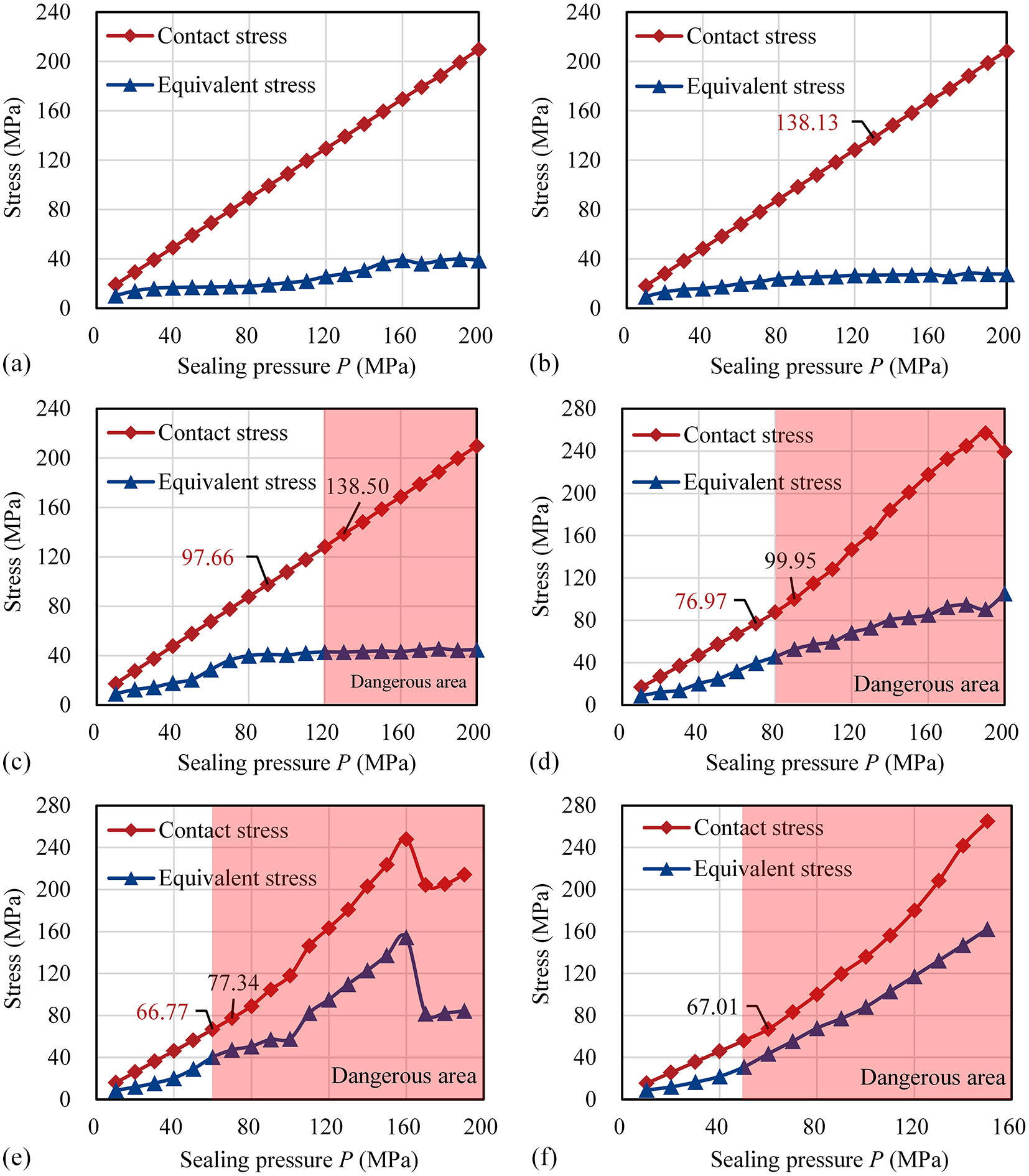
Changes of contact stress and equivalent stress of O-ring along with sealing pressure: (a) C = 0.0 mm, (b) C = 0.1 mm, (c) C = 0.2 mm, (d) C = 0.3 mm, (e) C = 0.4 mm, and (f) C = 0.5 mm.

Cloud pictures of contact stress distribution of O-ring: (a) C = 0.1 mm, (b) C = 0.3 mm, and (c) C = 0.5 mm.
As the sealing pressure and the sealing clearance increases to a certain level, the tendency of variation is no longer linear. At this moment, the data obtained in FEA go against the Stress Criterion. For example, as can be seen in Figure 6(d) (C = 0.3 mm), the contact stress under the condition of P = 90 MPa is about 99.95 MPa. And in Figure 6(c) (C = 0.2 mm), the contact stress under the same condition is about 97.66 MPa. With the sealing clearance increasing, the contact stress should decrease under the same condition. From P = 90 MPa in Figure 6(d), all the data go against the theory, which present inaccuracy and uncertainty of FEA by using the commercial software. Thus, according to these certain levels, we can determine a dangerous area of every case, which are depicted in Figure 6(c) to (f). Therefore, we can obtain a relatively conservative reference value of the safe sealing pressure of the O-ring of d2 = 6.99 mm under different conditions.
The results are shown as follows:
The contact stress of the O-ring is increased linearly as the sealing pressure increases in low-pressure domain, which accords with the Stress Criterion. With the sealing pressure increasing, the equivalent stress of the O-ring is also increased.
As the sealing clearance increases, the safe sealing pressure is decreased, which also accords with the Stress Criterion.
Compared to Figure 2(c), the contact stress distributions of the O-ring in every case accord with the theory, which can be seen in Figure 7.
Strain analysis
The changes of the equivalent strain and the principal strain of the O-ring along with the sealing pressure, and the effect of the sealing clearance are all investigated (see Figure 8). Some representative cloud pictures of equivalent strain of the O-ring are shown in Figure 9, which represent not only the strain distribution, but also the stress distribution, and from which the extrusion of the O-ring can be observed in some cases.
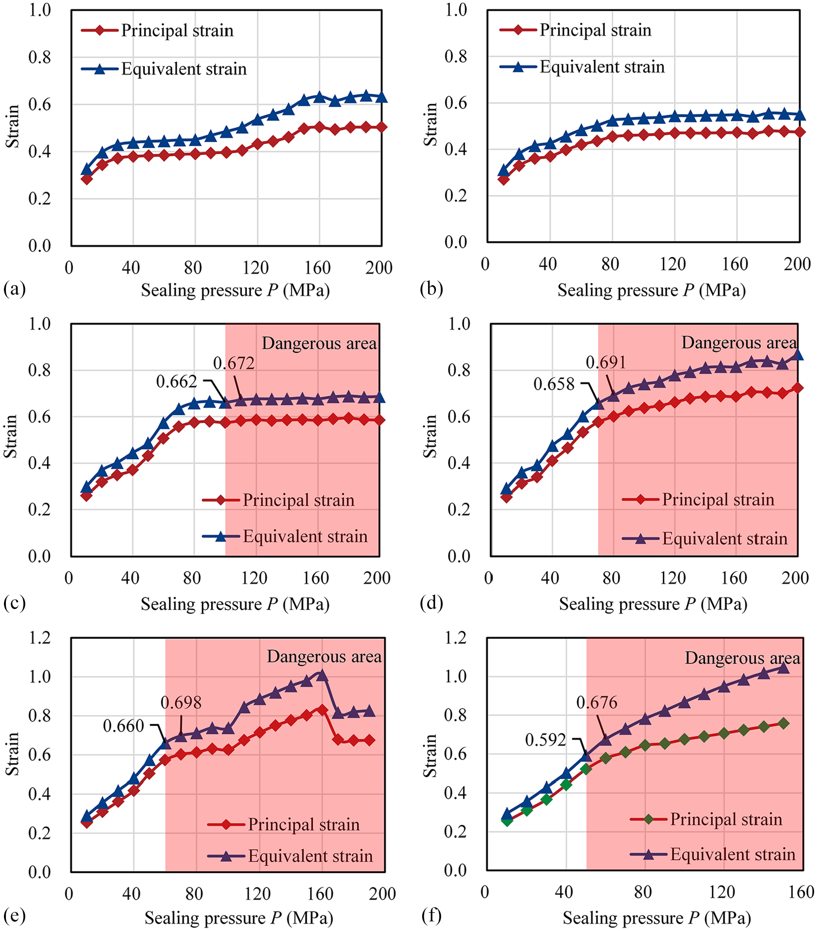
Changes of equivalent strain and principal strain of O-ring along with sealing pressure: (a) C = 0.0 mm, (b) C = 0.1 mm, (c) C = 0.2 mm, (d) C = 0.3 mm, (e) C = 0.4 mm, (f) C = 0.5 mm.

Cloud pictures of equivalent strain of O-ring: (a) C = 0.1 mm, (b) C = 0.3 mm, and (c) C = 0.5 mm.
From P = 70 MPa in Figure 8(d), the equivalent strains are all over 0.67, which goes against the improved Strain Criterion. Similarly, we can also obtain a dangerous area of every case. The moment when the contact stress began to go against the Stress Criterion is almost the moment when the equivalent strains began to go against the improved Strain Criterion. Thus, we have more reason to believe that the sealing performance of O-rings in dangerous areas cannot be accepted.
The results are shown as follows:
As the sealing pressure increases, the equivalent strain of the O-ring is increased. With the sealing pressure increasing, the principal strain of the O-ring is also increased with the similar trend of the equivalent strain. The principal strain is always smaller than the equivalent strain under the same condition, which can also be as a more conservative criterion in FEA.
As the sealing clearance increases, the safe sealing pressure is decreased, which accords with the Stress Criterion.
There is a stress concentration region inside of the O-ring, which can be seen clearly in Figure 9. When the sealing pressure is lower, the region is concentrated with a larger area, showing a good sealing statue of the O-ring. But as the sealing pressure increases, the O-ring is squeezed more and more seriously. Simultaneously, the stress region contracts toward the clearance between two sealing surfaces, and the concentration area becomes smaller and smaller. When the sealing pressure increases to a certain level, the extrusion can be observed clearly in some cases of Figure 9.
Discussions
Verification
The static sealing performance of the O-ring with d1 = 3000 mm and d2 = 6.99 mm have been analyzed in Section 3. The verification of the FE model is described as follows:
When the sealing pressure and the sealing clearance are lower, there is an approximate linear relationship between the contact stress and the sealing pressure, which is in accord with the automatic sealing theory or the Stress Criterion.
As the sealing pressure and the sealing clearance increase, the changes of the stresses deviate from the linear variation. This is mainly due to the errors of numerical computation and the limitation of M-R model. But, it can reflect the safe sealing pressure PS and the allowable maximum sealing clearance Cmax from the side, conservatively. The results show that the allowable maximum sealing clearance of the O-ring with d2 = 6.99 mm is about 0.6 mm when the sealing pressure P = 10 MPa. This is very close to the limit in Parker O-ring Handbook (Cmax = 0.5 mm), and these limits are usually strict.3,10
There is no direct experimental verification, and this kind of experiment will cost a lot and is challenging due to the high-pressure and the large size of O-rings. Based on the practical engineering application, the maximum equivalent strains of the O-rings in the DOCP3 is about 0.64, while the value in the DOCP4 is about 0.6679. Thus, the authors proposed an improved Strain Criterion, and the reliable of the results in this paper can be guaranteed by the combination of the Stress Criterion and the improved Strain Criterion.
Effect of cross-section diameter and sealing clearance
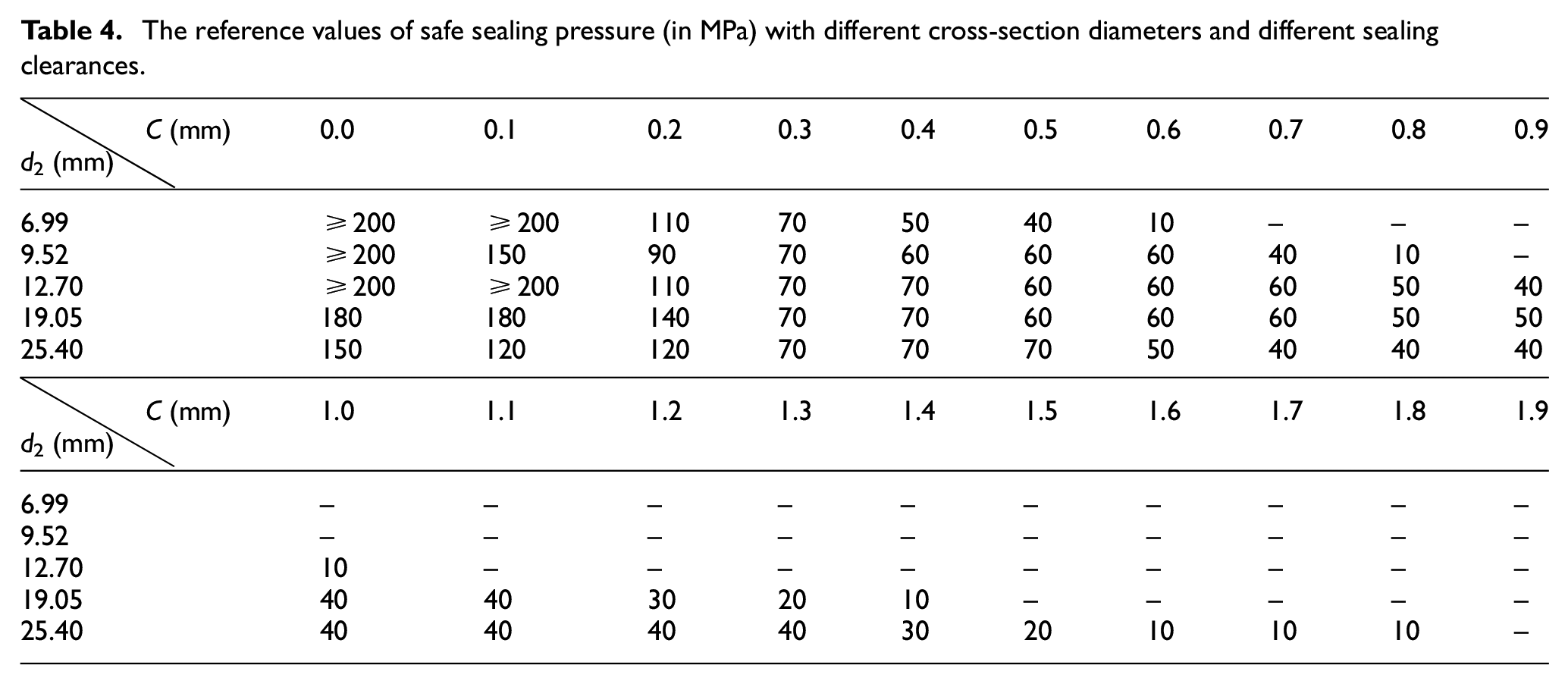
The changes of the equivalent strain of O-rings along with the cross-section diameter are also investigated, see Figure 10. And the reference values of safe sealing pressure with different cross-section diameters and different sealing clearances are ascertained by combination of the Stress Criterion and the improved Strain Criterion (see Table 4).

Changes of equivalent strain of O-rings along with cross-section diameter: (a) C=0.0 mm, and (b) C=0.1 mm.
The reference values of safe sealing pressure (in MPa) with different cross-section diameters and different sealing clearances.
The results are shown as follows:
As the cross-section diameter of O-rings increases, the equivalent strain and the maximum allowable sealing clearance are both increased.
As the sealing pressure increases, the increment of the equivalent strain becomes larger. It means that the O-rings with a large cross-section diameter may not be applicable to the high-pressure DOPCs, but it can allow a larger sealing clearance to be used in the low-pressure DOPCs.
The sealing clearance has more significance in designing O-ring static sealing in DOPCs. As for the high-pressure DOPCs, the cross-section diameter d2 should not be enlarged blindly, and how to control the sealing clearance is the primary work. And for the low-pressure application, the cross-section diameter can be enlarged properly so that a larger sealing clearance or a larger manufacturing tolerance can be used.
O-ring static sealing design of DOPCs
Table 4 can be a basic criterion to determine a proper cross-section diameter of non-standard large-sized O-rings used in DOPCs. For example, the O-rings with a cross-section diameter from 6.99 to 25.4 mm can all be used in a DOPC with 10-MPa pressure. But, when the cross-section diameter is 6.99 mm, the maximum allowable sealing clearance is 0.6 mm; when the cross-section diameter is 25.40 mm, the maximum allowable sealing clearance is 1.8 mm. Obviously, there is a trade-off between the price of O-rings and the cost of manufacturing.
To further illustrate how to use the Table 4, the FE model of a DOCP with 10-MPa pressure and 1000-mm inner-diameter is carried out based on ANSYS platform, which is shown in Figure 11. The sealing clearance induced by the expansion of the chamber due to sealing pressure is obtained by FEA. The results show that the radial sealing clearance is about 0.2 mm, and the axial sealing clearance is about 1.1 mm. Thus, at least two O-rings with d2 ≥ 6.99 mm should be set in the radial sealing position as the first-stage seal, and one or two O-rings with d2 ≥ 12.70 mm should be set in the axial sealing position if needed.

FE model and cloud picture of deformation of a DOCP with clamp quick-actuating closure.
It should be noted that, Table 4 just shows the reference values of safe sealing pressure of a specific material and the commonly used sealing structure in DOCPs. For different materials and different sealing structures, the corresponding FEA can be carried out based on the methodology of this paper.
What’s more, for the DOPCs with high-pressure (especially the FOD pressure), the sealing clearance must be controlled very well, which usually needs special designs (such as pre-stressed wire-wound chamber and yoke frame design) or other ancillary equipment to diminish the sealing clearance as many as possible. 2 In this situation, the sealing performance cannot be guaranteed by only using the elastomer O-ring. The anti-extrusion rings (back-up rings), the metal O-rings or their combination as well as any other innovative seals and sealing designs can all be considered. The anti-extrusion rings can be used in which the sealing pressure is more than 10 MPa,10,22 and the metal O-rings can be widely used in various fields with harsh working environment, such as high-pressure, high-temperature, corrosion, and radioactive radiation. 23
Conclusions
The static sealing performance of non-standard large-sized O-rings used in DOPCs has been studied with FE method in detail. An 2D axisymmetric FE model of O-ring static sealing in DOPCs was carried out. The three-order M-R model was used, and the material constants was obtained by uniaxial tension and compression tests accomplished by Zhang et al. 17 The “Ancient Coin” method was used to obtain the elements of better quality. The influence of the frictional coefficient and the inside diameter of O-rings was investigated. The stresses and the strains of the O-ring were analyzed. Moreover, the effect of the cross-section diameter of O-rings was investigated, and the reference values of safe sealing pressure with different cross-section diameters and different sealing clearances were ascertained. In this paper, the following conclusions can be obtained:
The maximum strains of the O-ring static sealing in some available DOPCs by the equivalent FE models were evaluated, and the Strain Criterion for sealing performance in FEA was improved. That is, the maximum equivalent strain should be below 0.67.
The frictional coefficient can be selected from 0.1 to 0.5 based on the practical lubrication condition, and the influence of the inside diameter of O-rings can be ignored in designing DOPCs.
The variation of the contact stress accords with the theory, and the stress concentration region inside the O-ring can be contracted toward the clearance between two sealing surfaces as the sealing pressure increases. The results of the allowable maximum sealing clearance under the condition of 10-MPa pressure are very close to the limit in Parker O-ring Handbook.
The reference values of safe sealing pressure with different cross-section diameters and different sealing clearances were ascertained, which is shown in Table 4.
The O-rings with a large cross-section diameter may not be applicable to the high-pressure DOPCs, but it can allow a larger sealing clearance to be used in the low-pressure DOPCs.
All in all, FEA is not magic, but it indeed can provide useful information to engineering design, because some related experiment will cost too much and is challenging, especially in the field of heavy industry. In this paper, the model verification has been considered by comparing with the basic theory and the real engineering application, which is equivalent to an indirect experimental verification. Since the practical engineering design is usually conservative, the results obtained in this paper can provide a more convincing guideline for designing non-standard large-sized O-rings used in DOPCs and any other similar pressure vessels.
Footnotes
Handling Editor: James Baldwin
Declaration of conflicting interests
The author(s) declared no potential conflicts of interest with respect to the research, authorship, and/or publication of this article.
Funding
The author(s) disclosed receipt of the following financial support for the research, authorship, and/or publication of this article: This work was supported by Zhejiang Key R&D Program (Grant No. 2021C03157), the “Construction of a Leading Innovation Team” project by the Hangzhou Municipal government, the startup funding of New-Joined PI of Westlake University with grant number (041030150118) and the funding support from the Westlake University and Bright Dream Joint Institute for Intelligent Robotics.