
Abstract
A novel feedforward control method of elastic-joint robot based on hybrid inverse dynamic model is proposed in this paper. The hybrid inverse dynamic model consists of analytical model and data-driven model. Firstly, the inverse dynamic analytical model of elastic-joint robot is established based on Lie group and Lie algebra, which improves the efficiency of modeling and calculation. Then, by coupling the data-driven model with the analytical model, a feed-forward control method based on hybrid inverse dynamics model is proposed. This method can overcome the influence of the inaccuracy of the analytical inverse dynamic model on the control performance, and effectively improve the control accuracy of the robot. The data-driven model is used to compensate for the parameter uncertainties and non-parameter uncertainties of the analytical dynamic model. Finally, the proposed control method is proved to be stable and the multi-domain integrated system model of industrial robot is developed to verify the performance of the control scheme by simulation. The simulation results show that the proposed control method has higher control accuracy than the traditional torque feed-forward control method.
Introduction
Industrial robots are widely used in modern industrial manufacture, such as paint spraying, welding, grinding 1 milling, 2 drilling, 3 and so on. In recent years, with the rise of intelligent manufacturing technology and the close combination of the artificial intelligence technology and industrial robots, the application of robots has been expanding to all walks of life. Since the rapid development of modern enterprises requires higher production efficiency, product quality and faster product iteration speed, the industrial robots have entered the development stage of high speed, high precision, heavy load, lightweight, and intelligent.
The traditional control method of joint industrial robot is PID 4 control algorithm which is not based on model. Each joint is regarded as an independent second-order linear system, and other coupled joint dynamics is regarded as external interference. This control algorithm is simple and easy to design. In some cases (such as low speed and stable working conditions) it can meet the accuracy requirements of the control system. However, the industrial robot is a complex and multi-domain coupling nonlinear system, the traditional PID control is usually hard to meet the high-speed and high-precision control requirements. With the development of industrial robot control technology, many control algorithms have been proposed such as fuzzy control, 5 optimal control, 6 dynamic surface control, 7 sliding mode control,8,9 fraction order control, 10 robust neural control, 11 torque feedforward control, 12 and so on. Among them, torque feedforward control is the most intuitive nonlinear control method. It is an effective control method which relies on the robot inverse dynamics, so sometimes it is also called inverse dynamic control. Compared with the model-free control methods, the inverse dynamic control usually can achieve better control performance, such as high tracking accuracy, low feedback gain coefficient, high adaptability to compliance control, and low energy consumption.
Robot inverse dynamic control technology firstly needs to establish inverse dynamic model to predict the feedforward torque. In most researches of the robot inverse dynamic control, the robot is regarded as rigid body. In effect, the synchronous conveyor with significant flexible characteristics and RV harmonic reducer are commonly used in the joints of industrial robot. The joint flexibility effect is significant, which may lead to mechanical resonance and affect the stability and tracking accuracy of the servo control system. Compared with the rigid-joint robot, the elastic-joint robot presents serious problems such as complexity, high nonlinearity, and large amount of calculation. The research results show that the difficulty of the inverse dynamic modeling of elastic-joint robot lies in the fact that the high order of robot joint angel and joint driving torque under the given trajectory are needed. 13 To deal with the elastic joints in the inverse dynamic modeling, Hopler and Thümmel 13 propose a symbolic method base on Lagrange theory to deduce the high-order dynamic equations. However, the method has inherent drawbacks: depending on the chosen coordinates and complex computation for symbolic operation in high-order derivation. Guarino Lo Bianco 14 think that Newton-Euler method is more efficient to derive the high-order kinematics and dynamics, and a recursive method based on Newton-Euler was proposed to compute the derivatives of actuator torques. More recently, Buondonno and De Luca15,16 proposed a method to analyze the inverse dynamics of the elastic-joint robot. But in the study, it is too complex to derive the high-order kinematics and dynamics because of using the Denavit-Hartenberg (D-H) technique. In recent years, as an analysis tool of modern geometric mathematics, the application of Lie group and Lie algebra in robot kinematics and dynamics has attracted more and more attention.17–19 Park et al. 17 firstly introduced Lie group to formulate the dynamic model of rigid-joint robot. Based on the study of the Park, Yang et al. 19 proposed a recursive Newton–Euler method based on Lie group to deal with elastic joints in the inverse dynamic analysis, but the studies were not applied to the robot inverse dynamic control.
The existence of flexible robot joints also makes the high-performance control of robot very complex and difficult. In Cai et al., 20 a kind of position control method based on double speed closed loops for elastic-joint robot is proposed to reduce turning error and nonlinear dead zone. This control method is pure feedback control so that the improvement of control performance is limited. To achieve excellent control performance, it is an effective method to add inverse dynamics feedforward on the basis of feedback control, which needs accurate inverse dynamic model to predict torque. Robot dynamic model is usually derived from expert domain knowledge. This modeling method is called analytical modeling, also known as knowledge-driven, physics-based, or mechanical modeling. In Kim and Croft, 21 and Moberg and Hanssen 22 the elastic-joint robot torque feedforward control is based on the fully analytical dynamic model. But the accurate analytical model is difficult to be established. In order to obtain the accurate dynamic model, parameter identification method is widely used to modify the nominal dynamic model. In Swevers et al., 23 a series of excitation trajectories are designed for the robot, and then different optimization algorithm are used to fit the parameters in the nominal dynamic model. In Schaal et al., 24 the local weight mapping regression method is used to estimate the dynamic model of the robot through simulation and experiment, and the estimated dynamic model is used in the feed-forward control. However, industrial robot is a complex multi-domain coupling nonlinear system, which has parameter uncertainty and non-parameter uncertainty. Only by analytical modeling and parameters identification, the accuracy of robot dynamic model is limited. In Zeinali and Notash, 25 an uncertainty estimator to compensate for the un-modeled dynamics, external disturbances, and time-varying parameters was used in the sliding control of the robot manipulator. The robot inverse dynamic model can also be established by machine learning techniques, which is called the data-driven modeling method. Machine learning is one of today’s most rapidly growing technical fields 26 ; there has been growing interest in applying machine learning to draw insights gained from the data in engineering. 27 In Nguyen-Tuong et al., 28 the inverse dynamics model of robot is established by nonparametric regression method. The fully data-based models lack of interpretability and it may suffer from inaccuracies as well when the working condition varies. So in Guo et al., 29 and Mei et al. 30 the hybrid analytical and data-driven modeling method was used to establish the dynamical model of the feed drive system. Reinhart et al.31,32 have used the hybrid analytical and data-driven modeling method to establish the kinematics model for soft robots and the inverse dynamic model for rigid robots. But the author’s research mainly focused on rigid robot and the inverse dynamic model is not applied to the control.
From the above analysis, it can be seen that the inverse dynamic control of elastic-joint robot mainly faces two problems: one is the derivation calculation of high-order kinematics and dynamics is complex and tedious, the other is that the accurate dynamic model is hard to be established. To deal with these problems, an inverse dynamic control approach for elastic-joint robot based on hybrid dynamic model is proposed in this paper. Firstly, for simplicity and efficiency, the analytical inverse dynamic model of elastic-joint robot is established based on Lie group and Lie algebra. Then, a radial basis function (RBF) neural network model is combined with the analytical inverse dynamic model and the inverse dynamic control based on the hybrid model is proposed. The control law is proved to be stable by mathematical. At last, a multi-domain integrated system model of industrial robot is established and the proposed control method is validated by simulation. The simulation results show that the proposed control method is superior to the traditional inverse dynamics feedforward control.
The rest of the paper is organized as follows. In Sect.2, some basic background of Lie group and Lie algebra is introduced. In Sect.3, the elastic-joint industrial robot inverse dynamic model is established based on Lie group. In Sect.4, the inverse dynamic control method based on hybrid analytical inverse dynamic and data-driven model is proposed and the mathematical proof is given. In Sect.5, the multi-domain integrated system model of industrial robot is established and the proposed control method is validated by simulation. Finally, the conclusions are summarized in Sect.6.
Basic background of Lie group and Lie algebra
In the analysis of robot kinematics and dynamics, the problem of position and orientation transformation is often faced. Based on the traditional D-H technique, it is hard to calculate the high-order derivation of the robot kinematics and dynamics. In effect, the transformation space of all possible rigid body motions is an element of Lie group. In this section, some basic background of Lie group and Lie algebra is introduced. The detail of related theories can be referenced to the work of Selig. 33
Previous knowledge of Lie group and Lie algebra
Lie group is not only a group, but also a smooth manifold. The tangent space of the unit element of a Lie group is called the Lie algebra of this Lie group. All the ration matrix of rigid body is a subgroup of Lie groups:

The position and orientation of rigid body in 3D space can be described by the transformation matrix

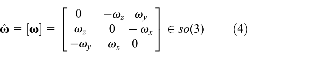
where

Every Lie group has its corresponding Lie algebra, which describes the local properties of Lie groups. The corresponding Lie algebra of

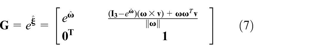
The transformation from Lie algebra to Lie group can be described by using the following exponential mapping:

An element of a Lie group can also be identified with a linear mapping between its Lie algebra via the adjoint representation. Suppose

Similarly, an element of a Lie algebra can also be identified with a linear mapping between its Lie algebra via the Lie bracket. If

These two mappings can be calculated in matrix forms:


In the same way, the corresponding dual operator


Rigid-robot dynamics using Lie group
For series industrial robot, the joint between adjacent rigid links is revolve joint. Each revolve joint can be associated with a twist and the twist coordinate expressed in the reference frame is defined as follows:

where
The Euclidean transformation that describes the position and orientation of rigid body is an element of Lie group

where

Then by forward recursion (for


According to the theory of Newtonian rigid body dynamics, the resultant force and torque acting on the rigid body in the local coordinate frame
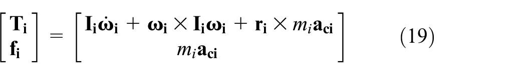
Based on the adjoint transformation property of Lie algebra, the above equation can also be simplified and expressed as follows:

where

Furthermore, according to the interaction principle of force, the resultant force and torque can also be expressed:

Therefore, by backward recursion (for

And the driving torque of each joint is:

Based on the derivation of the above recurrence equation, the matrix form of the robot rigid body dynamics model can be represented as follows:

where
Elastic-joint robot analytical inverse dynamic model based on Lie group
When the joint flexibility is considered, the derivation of the robot inverse dynamic model is becoming extremely complex. By traditional D-H parameters method, it is hard to deal with this kind of problem. So in this section, the analytical inverse dynamic model of elastic-joint robot is derived using Lie group and Lie algebra. The related researches can also be seen in Yang et al. 19
Elastic joint dynamic model
The dynamic model of elastic joint based of linear torsion spring is first proposed by Spong. 34 In the study, the elastic joint of the robot is simplified as a linear torsion spring, and the torsion deformation is assumed to be within the range of elastic deformation. Based on the Spong’s research, the elastic-joint industrial robot is presented schematically in Figure 1.
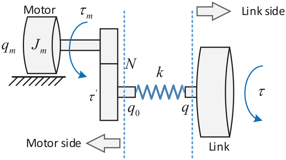
Schematic diagram of single elastic joint of robot.
For n-DOF industrial robot, its analytical dynamic model can be simplified as the elastic joint and the rigid link are connected in series in turn. The output torque of all the motors are represent as the vector


In the robot control, the given command signal is usually the trajectory of end-effectors. By inverse kinematic and inverse dynamic calculating, only the rotation angel


represents the nonlinear uncertainties.
High-order kinematics and dynamics
From the equation of above, it can be seen that the key problem of the inverse dynamics calculation of the elastic-joint robot is how to efficiently calculate the second derivative of the rigid robot driving torque. In this paper, the high-order kinematics and dynamics is derived based on Lie group and Lie algebra.
With the given Cartesian trajectory

Differentiating the above equation, the joint acceleration
The six dimensional generalized jerk and snap can be derived by differentiating the equation (18). Combined with the equations (17) and (18), through forward recursion (for i = 1, 2, …n), we can obtain:
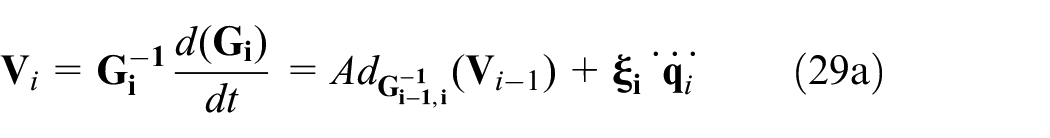


Similarly, by differentiating the equation (23), the first derivative and second derivative of generalized forces


Then the


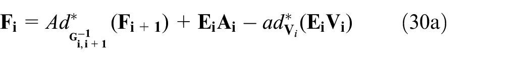
Combined with the equation (27), the elastic-joint industrial robot inverse dynamic calculation can be summarized as a flowchart as shown in Figure 2.
Elastic-joint robot inverse dynamic calculation flowchart.
The inverse dynamics modeling method of elastic-joint robot based on Lie group and Lie algebra can simplify the modeling process and improve the computing efficiency compared with the traditional D-H modeling method. Therefor this modeling method has more advantages in inverse dynamics feedforward control. In order to analyze and prove this, the computational complexity of two different modeling methods is analyzed, and the simulation models of two different modeling methods are established to compare the simulation efficiency. For the sake of simplicity, the input of the two different models is given the same joint angular displacement of sinusoidal signal, and the simulation time is given as 5 s. The comparison of complexity analysis and calculation efficiency is shown in Table 1.
Comparison of computation complexity and efficiency of two different modeling methods.

It can be seen from Table 1 that the modeling method based on Lie group and Lie algebra is more efficient to calculate the inverse dynamics of flexible joint robot. Compared with the traditional D-H parameter method, the efficiency is increased by 22.7%
Inverse dynamic control based on hybrid model
Principle of hybrid modeling
The principle of this hybrid modeling method is shown in Figure 3. It can be seen from the figure that the hybrid model is composed of analytical model, data-driven model, and the coupling relationship between them. If


Schematic diagram of the hybrid modeling method.
In the formula,


Design of the controller
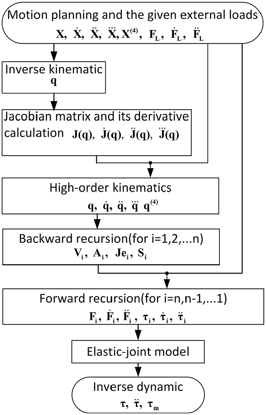
As mentioned in the introduction, the industrial robot is a complex nonlinear system, the pure analytical inverse dynamic model can suffer from inaccuracy because of parameter uncertainties and non-parameter uncertainties. The inaccuracy inverse dynamic model is not conductive to high speed and high precision control. So in this paper, the hybrid analytical and data-driven inverse dynamic model is developed and the inverse dynamic control method based on the hybrid model is proposed. The analytical model is derived in the Sect.3, the data-driven mode is based on RBF neural network and the coupling relationship between the analytical model and the data-driven model is parallel coupling. The weights of RBF neural network are adjusted adaptively and updated online. The proposed control method based on the hybrid inverse dynamic model can be seen in Figure 4.
Inverse dynamic control based on hybrid model.
The RBF neural network has the universal approximation property,
35
so the data-driven model is established using RBF. If

then the output of RBF can be expressed as equation in which

In the Figure 4, the input of the RBF neural network is a vector composed of joint angular displacement and its derivatives, and joint angular control error and its derivatives.
Stablity analysis
The proposed control law can be expressed as follows,

where

By applying equation (34) to equation (27a), the following equation can be obtained,
where
By equation (27b), the joint driving torque error is calculated as

Its second derivations is

As the fourth derivative of the link error is much larger than the second or third derivatives, the terms,

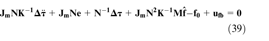
By applying equations (37) and (39) to equation (36), the following equation can be obtained,

where
The feedback control law can be referred to Moberg and Hanssen, 22

where
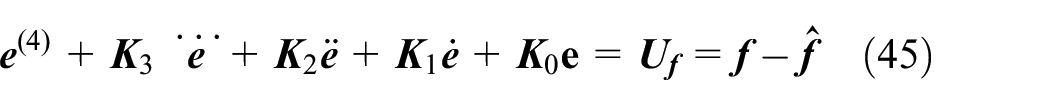
If the

The servo error

In equation (44),

The

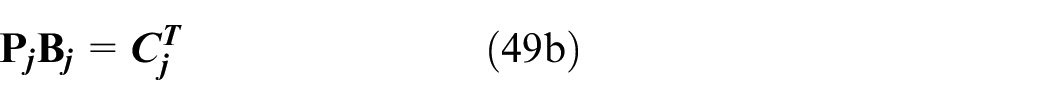
where the matrices


The state vector
Then the error dynamic equation of the entire robot system in state-space form is given by


where


Now use Lyapunov theory to analyze the stability. The following Lyapunov function is defined
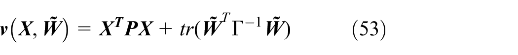
where

Therefore, if we chose

we have

which is non-positive because
Simulation and verification
Multi-domain integrated robot system model
In order to validate the performance of the proposed control method, a multi–domain industrial robot system model is established. Different from traditional model, the model established in this paper integrated mechanical, control and electrical subsystems. It is much closer to the real robot system. The system model is mainly composed of mechanical part, electrical subsystem, control subsystem and trajectory planning algorithm. The model topology can be seen in the Figure 5.

Topology of the multi-domain integrated robot system model.
The robot is the typical 6-DOF industrial robot and the main parameters are show in the following Table 2.
Main parameters of industrial robot system.

The initial orientation (
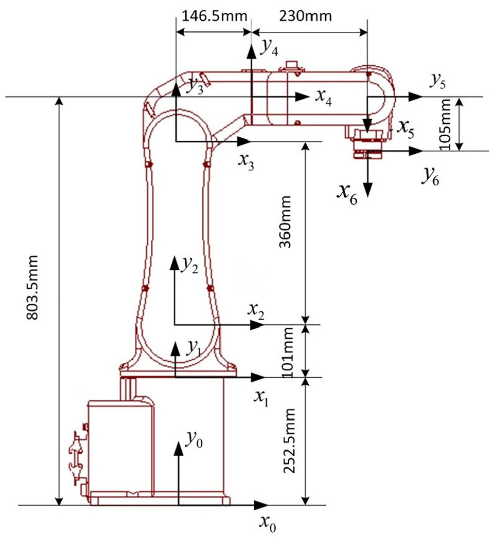
Mainly geometric size and frame configuration.
Simulation and analysis
In order to analyze the proposed control algorithm, two types of typical trajectories are given for simulation: one is the line trajectory and another is circle trajectory. Fifteen segments S-type velocity planning is used for motion planning. The trajectory and motion planning can be seen in the Figure 7.

Trajectory and motion planning.
Because of the accurate robot dynamic model is hardly to be established, the control performance of the traditional inverse dynamic feedforward control method is limited. In order to demonstrated that the control method based on hybrid inverse dynamic model proposed in this paper can avoid the decrease of control accuracy caused by the inaccuracy of the model to some extent, three different simulations are performed. In the first case, the inverse dynamic model is completely accurate, that is the inverse dynamic control is based on accurate model (IDC-AM). In the second case, it is assumed that the estimated dynamic parameters (joint stiffness, link mass, and link inertia tensor) are 90% of the real value. That is to say the inverse dynamic control is based on inaccurate model (IDC-IM). In the three case, the inaccurate model is combined with the RBF neural network model, the inverse dynamic control is based on the hybrid model (IDC-HM). The simulation results in these three cases are compared.
This research is mainly focused on trajectory tracking precision. When the straight line command trajectory is given, the simulation results can be seen in Figure 8. For conveniently reading the figure, the straight line contour error is magnified by 40 times.

Simulation results of straight line trajectory tracking performance.
It can be seen directly from the Figure 8 that trajectory tracking precision has decreased a lot when the inverse dynamic model is inaccurate. When the inaccurate model is combined with the RBF neural network model, the trajectory tracking precision has improved. Similarly, when the circle command trajectory is given, the same conclusion can be found, as can be seen in the Figure 9 (The contour error is magnified by 40 times). The compared simulation results shows that the inverse dynamic control based on hybrid model can improve the control performance.

Simulation results of circle trajectory tracking performance.
The curve of contour error respect to time in the three cases can be seen in Figures 10 and 11. The control performance can be compared more clearly from the figures. In order to evaluate the contour error quantitatively, the maximum absolute error (MAE) and root mean square error (RSME) are evaluated. The details can be seen in Table 3. It can be seen in the table that the MAE and RSME of IDC-HM contour error are both smaller than that of IDC-IM whether the command trajectory is straight line or circle. The simulation results shows that the elastic-joint industrial robot inverse dynamic control based on hybrid model proposed in this paper can overcome the bad influence on the control performance caused by the inaccuracy of the dynamic model.
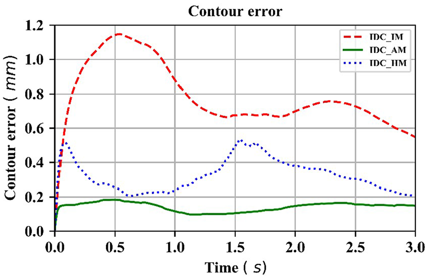
Comparison of the straight line contour error.

Comparison of the circle contour error.
Comparison of contour error of different control method.

The influence of load on the robot control performance is also analyzed. Assume that under the condition of circular trajectory planning in Figure 7, a 200 N resistance is applied at the end of the robot along the tangent direction of the arc trajectory at the time of 0.6 s, and the direction of the force is always opposite to the direction of the speed, as shown in Figure 12. Using the traditional inverse dynamics feedforward control method, this sudden increase of load is difficult to be considered in the inverse dynamics model. Therefore, the uncertainty of robot end-effector load will inevitably affect the performance of traditional inverse dynamics feedforward control method. If the feedforward control method based on hybrid inverse dynamic model proposed in this paper is adopted, the influence of load uncertainty on control accuracy will be weakened. In the case of sudden change load applied at the end-effector of the robot, the control performance of different control schemes is compared through the simulation analysis based on the multi domain system synthesis model of the robot, and the superiority of the control method proposed in this paper is verified.

The given load force curve of robot end-effector.
As shown in the Figure 13, the simulation results of trajectory tracking performance under two different control schemes are compared, that is, the traditional inverse dynamics feedforward control with inaccurate model and the proposed feedforward control based on hybrid inverse dynamic model. It is obvious from the figure that the trajectory tracking accuracy of the proposed feedforward control method based on hybrid inverse dynamic model is higher.

Position tracking error comparison of different control schemes under load disturbance.
Industrial robot is a nonlinear complex system, it is difficult to get accurate dynamic model based on mechanism modeling, so the inverse dynamic control based on pure analytical model is hard to achieve high control performance. The simulation results verified this conclusion and from the simulation results, if can be seen that if the analytical mode is combined with the data-driven model, the inverse dynamic control based on the hybrid model can improve the trajectory tracking performance. The advantage of the proposed control method is demonstrated by the simulation results.
Conclusions
This paper proposed an inverse dynamic feedforward control method of industrial robot with elastic joints based on hybrid model. The hybrid model is composed of analytical inverse dynamic model and data-driven model. Considering the elastic joint of the industrial robot, the inverse dynamic analysis is extremely complex, so in this paper the analytical model is derived based on the theory of Lie group and Lie algebra. Because of the complexity of the real robot system, the pure analytical model can hardly achieve high accuracy. The data-driven model is used to compensate the parameter uncertainties and non-parameter uncertainties. In order to validate the propose control method, the multi-domain integrated robot system model is established and by simulation, the control performance is compared with the traditional inverse dynamic control. The simulation results demonstrated the advantage of the proposed control method. The control method proposed in this paper can overcome the influence of the uncertainty of the inverse dynamic model on the control performance to a certain extent, improve the control performance of the flexible joint robot, and has important application value for realizing the high-precision control of the robot.
Footnotes
Handling Editor: James Baldwin
Declaration of conflicting interests
The author(s) declared no potential conflicts of interest with respect to the research, authorship, and/or publication of this article.
Funding
The author(s) disclosed receipt of the following financial support for the research, authorship, and/or publication of this article: This research was funded by [National Key R&D Program of China] grant number [2019YFB1706501]. The support is gratefully acknowledged.