
Abstract
Spiral bevel gear is widely used in various mechanical transmission systems, such as tractor transmission system. Because it is mainly used in the heavy-load conditions, it would most likely resonate within the rated speed, resulting in tooth fatigue damage. In this paper, based on the principle of meshing and gear tooth machining, the spherically involute tooth profile equation of spiral bevel gear is deduced and the precise modeling method based on the CATIA is studied. The natural frequency and modal shape under free vibration are obtained by the finite element method (FEM), the influence of web thickness and web hole on the natural frequency of driven gear plate is analyzed as well. In addition, the experimental modal of bevel gear pair is carried out based on a multiple-reference impact test, Modal Assurance Criterion (MAC) is calculated, the three-dimensional modeling accuracy and the finite element analysis reliability are verified. The results show that the error between the measured frequency of bevel gear pair and the calculated frequency of the finite element simulation are both within 5%, and the MAC is above 0.8. The fourth-order natural frequency is the most sensitive to the web thickness, the second-order natural frequency is the most sensitive to the web hole.
Keywords
Introduction
Spiral bevel gear occupies several strong points like good carrying capacity, and it is widely used in aerospace engineering, precision machine tools, and other modern mechanical transmission fields. At present, spiral bevel gear is developed to be more and more lightweight. As the gear weight is reduced, the excitation force and noise can increase, while affecting the operating efficiency, and even resulting in failure of the entire transmission system. Therefore, an analysis of vibration characteristics of a spiral bevel gear is made with the purpose of finding out the weakness and avoiding resonance failure, thereby improving the service life of spiral bevel gear. It has an important research significance and application value for the spiral bevel gear structural design.
In his spiral bevel gear modeling, Litvin et al.1,2 replaced nonconjugate tooth surfaces for conjugated tooth surfaces in spiral bevel gears, and the conjugated surfaces were generated by two conical surfaces. Fan3–5 presented the theory of the face hobbing generation method, mathematic models of tooth surface generations. Shi et al. 6 derived the tooth profile equation of noncircular bevel gear according to the generation method by using a bevel gear cutter. Li 7 proposed a nonlinear dynamic model of a spiral bevel gear pair and asymmetric mesh stiffness was taken into account. Tsai and Hsu 8 derived the meshing constraint equation of bevel gear sets with point-contact characteristics. Liu et al. 9 developed a new method for pitch cone based on two mathematical iterations and selected and obtained gear geometry parameters for acceptable geometries of pinion and wheel.
In order to predict cutting force in face-milling of spiral bevel gears, Zheng et al. 10 proposed a semi-analytical model, it is faster, more precise and more effective than chip-simplify method. Jiang et al. 11 presented a new method for calculating the tangential milling force of cutter teeth, the changing rule of cutting area of the tooth surface and the boundaries of the cutting area. Dooner 12 developed a process to establish a generalized geometric framework for spatial involute curves, and their curves are non-panar and there exists slip as the taut chord is unwrapped.
Within the scope of the spiral bevel gear test, Litvin et al. 13 tested the contact patterns of pinion tooth surfaces for the optimized design based on the application of an adjusted contact path. Spievak et al. 14 and Ural et al. 15 investigated the crack propagation of spiral bevel gears under a non-proportional load, and the predictions were compared to experimental results. Lewicki et al. 16 proposed advanced-design spiral bevel gears and then noise and vibration tests were performed on all sets of each pair in an OH-58D helicopter transmission system. Long et al. 17 conducted a double circular arc spiral bevel gear test, the vibration signal and dynamic characteristics were obtained by the wavelet packet analysis method. Dempsey18,19 evaluated the capability of detecting gear surface pitting fatigue and other generated failure modes on spiral bevel gear teeth using gear condition indicators.
According to the research above, there’s still difficulty to obtain an accurate three-dimensional model, due to the rather complex curve, cylindrical gear tooth profile modeling is not suitable for spiral bevel gear. A lot of researches are about spiral bevel gear, but very few relevant researches concern the accurate modeling of spiral bevel gear and the influence of web structure parameters. Therefore, it is important to conduct researches to empower further study about contact simulation analysis of spiral bevel gear. In addition, there are few literatures about the experimental test of spiral bevel gear natural characteristics.
Regarding presented, the main purpose of this work is to put forward the mathematical modeling method of Gleason spiral bevel gear and carry out a modal shape test, which could be a reference for the structural design of spiral bevel gear pair.
To clarify the methodology, research work flow of this work is shown in Figure 1.
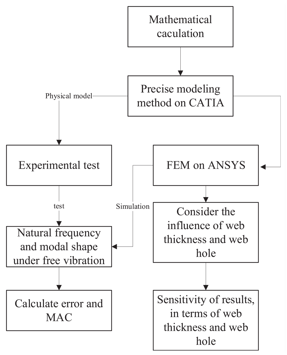
Research workflow.
Modeling and experimental test
3D solid modeling of spiral bevel gear
Spiral bevel gear meshing schematic is depicted in Figure 2. It can be seen that the meshing of conjugate tooth profiles takes place on the spherical surface with cone O with its center and outer cone distance as the radius. Therefore, the theoretical profile of the spiral bevel gear is spherically involute.
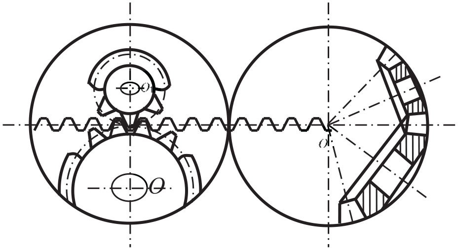
Meshing of spiral bevel gear.
In the spherical coordinate, the spherically involute equation on one side of outer space width is:
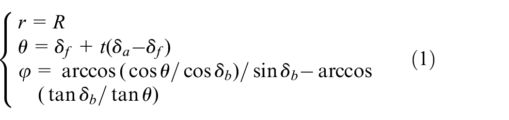
where δ b is the base angle; δ f is the root angle; δ a is the tip angle; R is the outer cone distance; t is modification coefficient.
The spherically involute equation on the other side of outer space width is:

here, z is the tooth number; φ b is the tooth thickness base angle.
When spiral bevel gears are the subject of the cutting processing, 20 the tooth pitch surface unfolded picture is shown in Figure 3.

Unfolded pitch surface.
The distance between cutting tool circle O1 and cone circle O is:

where β m is the mean spiral angle; Rm is the mean cone distance; Rd is the radius of cutting tool.
In circle O1, offset angle S of outer cone circle and inner cone circle are:


here, B is the tooth thickness.
In circle O, the offset angles j of outer cone circle and inner cone circle are:
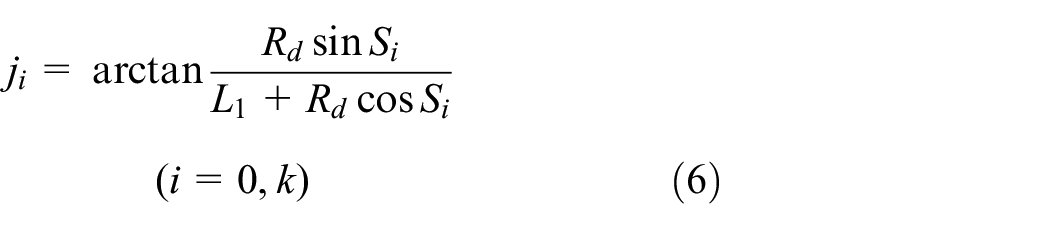
According to the spherical geometrical relationship, the spherical angle q corresponded to the plane angle j could be:

here, δ is reference cone angle.
In order to improve the accuracy of the three-dimensional model, equally spaced auxiliary spherically involute lines are inserted in the direction of the tooth line. Substitute (R−B) to (R−0.1nB) in equations (1), (4), and (5), and n is followed by 1, 2, 3…9…, then the involute equation could be rederived. The modeling method is similar to Reference 6, however, the accuracy of spiral bevel gears is improved.
The distance between cone O and any point on the path of cutter head is:

In Spherical coordinate system, equation of Tooth root profile curve is:

here, β f is the tooth root deflection angle.
Substract
In the same way, the equation of the tooth profile curve can be expressed as:

here, β a is the tooth top deflection angle
Based on the derived involute equation, key points of the curve are established by a “law command” in the CATIA, the tooth flank is modeled by a “split command,” and the parametric modeling of the spiral bevel gear can be achieved. The generated typical three-dimensional model is shown in Figure 4, the parameters are shown in Table 1.

Three-dimensional model of spiral bevel gear: (a) tooth flank, (b) solid tooth, (c) driver gear, and (d) driven gear.
Gear parameters.

Finite element modeling of spiral bevel gear
The geometrical model from the CATIA was imported into the ANSYS workbench for the finite element analysis. In order to improve the finite element calculation accuracy, a certain mesh density is applied firstly based on the hexahedral meshing method, then the mesh density is refined in the tooth flank. The mesh size in the whole model is defined as 6 mm, and the size of tooth flank is defined as 3 mm, so as to ensure the rationality of meshing and maximum efficiency of calculation. After several trial calculations, the difference of the calculation results is small, the calculation result converges. Figure 5 shows the finite element model of the spiral bevel gear pair under proper mesh calculation. In this model, the node of driver gear is 90,265, and the element is 26,370; the node of driven gear is 105,101 and the element is 31,090. The calculation results tend to converge, which means the quality of mesh is reliable. The FEM and physical models of spiral bevel gear are shown in Figure 5.

FEM and physical models of spiral bevel gear: (a) driver gear, (b) driven gear, and (c) physical model.
Experimental test of spiral bevel gears
The multiple-reference impact test is conducted for a modal test of the spiral bevel gear pair. The hammer is used to excite different reference points of the experimental products. The reference points are shown in Figure 5(c). At the same time, the acceleration and force signals are collected and processed, and the vibration frequency and modal shape are obtained. OROS OR34 four-channel dynamic signal analyzer, PCB U356A08 triaxial accelerometer and PCB 086C20 impact hammer are applied in the test. The sampling frequency is 20 kHz, the test equipment and the boundary conditions are shown in Figure 6.
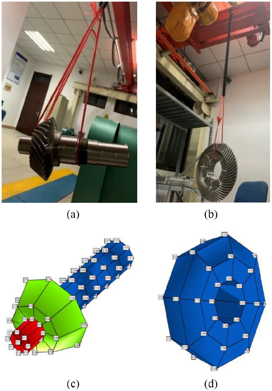
Experimental test of spiral bevel gear: (a) boundary condition of driver gear, (b) boundary condition of driven gear, (c) reference points of driver gear, and (d) reference points of driven gear.
In the finite element model, it is relatively easy to test whether the natural frequencies between the FEM method and the test are equal, and it is not so intuitive to be tested whether the two modal shapes are identical. In order to describe the correlation between the two modal shapes, numerical methods such as the Modal Assurance Criterion (MAC) is defined as: 21

where
Calculation and analysis
Natural characteristics calculation of spiral bevel gears
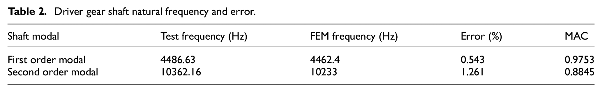
The first two natural frequencies of the driver gear shaft are obtained by the FEM method and experimental test as shown in Table 2. It can be seen from the table that the first mode frequency is 4486.63 Hz, the error between two methods is 0.543%, The MAC value is 0.975; the second mode frequency error between two methods is 1.261%, and the MAC value is 0.8845. Therefore, the accuracy of the first mode is higher and the modal shape correlation is better. Modal shapes of driver gear shaft are shown in Figure 7, it can be seen from the figure that the first two modes are mainly bending vibration modes.
Driver gear shaft natural frequency and error.

Driver gear shaft modal shape: (a) first modal shape based on FEM, (b) second modal shape based on FEM, (c) first modal shape based on test, (d) second modal shape based on test, and (e) MAC value.
Similarly, the first four natural frequencies of the driven gear plate can be obtained, as shown in Table 3. It can be seen from the table that the first order is 3423.5 Hz, and the error between the test frequency and the FEM simulation frequency is less than 5%, the MAC values are all greater than 0.83, so the correlation between the modal shape is very high. Modal shapes of driven gear are shown in Figure 8, it can be seen from the figure that the first four modes based on FEM simulation and experimental test have identical modal shapes.
Driven gear plate natural frequency and error.


Driver gear shaft modal shape: (a) first modal shape based on FEM, (b) second modal shape based on FEM, (c) third modal shape based on FEM, (d) fourth modal shape based on FEM, (e) first modal shape based on test, (f) second modal shape based on test, (g) third modal shape based on test, (h) fourth modal shape based on test, and (i) MAC value.
Influence of web thickness on each mode
The natural characteristics of spiral bevel gear depends on the structural parameters, and have a low impact on the operating conditions, so the change of web structure will have a great impact on the natural frequency and mode. In this paper, five gear models were established with different web thickness but with the same other parameters. These models are: 60 mm web thickness (Gear 1), 55 mm web thickness (Gear 2), 50 mm web thickness (Gear 3), 45 mm web thickness (Gear 4), and 40 mm web thickness (Gear 5) respectively. The first four modal shapes and natural frequencies are calculated, the modal shape is consistent with the one shown in Figure 8, and the natural frequency of each order under the influence of web thickness is shown in Figure 9. As it can be seen from the figure, when the web thickness decreases, the natural frequencies of each order go down as well, but the decreasing amplitude tends to be stable. The fourth-order natural frequency is most sensitive to the web wall thickness, it shows the sharpest declining trends.
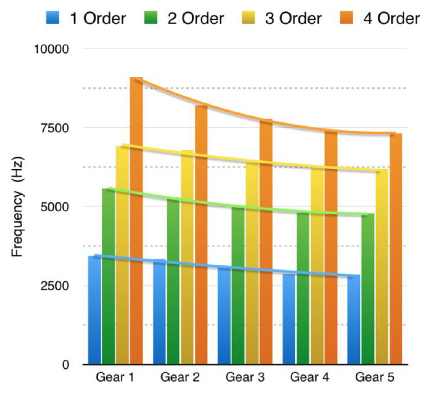
Influence of web thickness on natural frequency of driven gear.
Influence of web hole on each mode
The change of web hole also has a great influence on the natural characteristics of the driven gear plate. In this paper, the natural characteristics of five gear models are studied with different web holes but with the same other parameters. Their structural parameters are as follows: 30 mm web hole radius (Gear 6), 35 mm web hole radius (Gear 7), 40 mm web hole radius (Gear 8), 45 mm web hole radius (Gear 9), and 50 mm web hole radius (Gear 10). The first four modal shapes and natural frequencies are calculated respectively, and the natural frequency of each order under the influence of web hole is shown in Figure 10. As seen from the figure, when the radius of web hole increases, the natural frequency of each order decreases, and the second-order natural frequency declines most obviously. Therefore, the second-order natural frequency is the most sensitive to the web hole.

Influence of web hole on each natural frequency.
Conclusion
Based on the principle of meshing and gear cutting process, the involute and tooth equations of the spiral bevel gear are obtained. The three-dimensional model and finite element model of spiral bevel gear are established, the experimental test is carried out based on the multiple-reference impact method. In addition, the MAC is calculated, and the web structure influence is analyzed. This work carried out an accurate method for flank profile modeling, it could bring opportunities for more accurate contact simulation of spiral bevel gear. Meanwhile, the comparisons between simulations and experimental tests of natural frequency could be a reference for spiral bevel gear designing and testing.
Based on the research, the following conclusions are obtained:
The inserted auxiliary spherically involute equation in the direction of tooth profile can help to improve the accuracy of spiral bevel gear model.
For the driver gear shaft, the first-order mode has higher testing accuracy and better modal shape correlation; for the driven gear plate, the second-order mode has higher testing accuracy and better modal shape correlation. The values of MAC are all above 0.8, so the correlation between the test mode and the simulation mode is relatively high.
For the driver gear shaft, the error between the testing frequency and the FEM calculated frequency is within 2%; for the driven gear plate, the error value is within 5%.
For the driven gear plate, the fourth-order natural frequency is the most sensitive to the web thickness, while the second-order natural frequency is the most sensitive to the web hole.
Footnotes
Handling editor: James Baldwin
Declaration of conflicting interests
The author(s) declared no potential conflicts of interest with respect to the research, authorship, and/or publication of this article.
Funding
The author(s) disclosed receipt of the following financial support for the research, authorship, and/or publication of this article: The work described in this paper is fully supported by Nanjing Vocational University of Industry Technology Foundation (Grant No. YK20-04-06); China Postdoctoral Science Foundation (2020M671516); National Key Laboratory of Science and Technology on Helicopter Transmission (HTL-O-20G02); Natural Science Foundation of the Jiangsu Higher Education Institutions of China (2021).