
Abstract
The distribution and characteristics of internal flow field of the impeller with crack damage in service environment was investigated via numerical simulation with RNG k-ε turbulence model. The diffuser and volute are added based on the original impeller to simulate the internal flow field comprehensively. It was found that along the flow direction, the pressure, velocity, and temperature of the fluid increase continuously, and the maximum value appears near the outlet of the impeller. The maximum pressure and velocity in the crack area are distributed around the middle section and the trailing edge of the crack. Entropy production theory was applied in the study of internal flow, which reveals that the entropy production becomes larger around the crack. The further propagation of the crack is promoted by the opening force perpendicular to the entrance direction of the middle crack, the corrosion propagation at the rear edge of the crack, and the thermal deformation of the blade. The accelerated crack process will finally lead to the blade fracture accident.
Keywords
Highlights
The flow characteristics of impeller with crack was numerically investigated.
The maximum flow parameters appear near the trailing edge of the impeller outlet.
The velocity impact and pressure accelerate the corrosion cracking of the impeller.
The temperature difference results in nonuniform heating and stress deformation.
The entropy production becomes larger around the crack region.
Introduction
Centrifugal compressor is used to compress and transport a variety of gases in chemical production, and is widely applied in mining, refrigeration, metallurgy, and other fields. The design, manufacture, service, and maintenance of centrifugal compressor are of vital importance to the lifespan of the equipment, and the blade is the key factor. Blades work at high rotational velocity producing high centrifugal forces. In corrosive environment, such as seawater, the corrosion pit will appear on the blades. Corrosion pitting has been found to be responsible for the nucleation of fatigue crack. 1 Huge economic loss can be caused by stress corrosion crack of centrifugal compressor. 2 As a result, many scholars have done a lot of research on the initiation and propagation of centrifugal compressor blades’ crack. At present, the research on stress corrosion crack of centrifugal compressor impeller is mainly focused on two aspects: one is based on the experimental study of common materials in the working condition3–6; the other is the verification by using the numerical simulation of the internal flow field of the impeller.7,8
In the actual service environment, because of the complex structure of the impeller, the changes of the structure of the impeller, diffuser and volute can lead to complex and changeable internal flow field. It is complicated to study the flow field in the impeller theoretically, and it is difficult and costly to understand the distribution of the internal flow field through experiment.9,10 The emergence of computational fluid dynamics (CFD) technology has successfully solved this problem. By analyzing the internal flow characteristics of fluid machinery using numerical simulation, it not only shortens the research time, but also can obtain the data which is difficult to be obtained by experiment. In the field of fluid machinery, more and more schemes are implemented and verified via efficient and energy-saving CFD.11–18 As a new scientific research method, it plays an increasingly important role. Many researchers have studied the internal flow field of centrifugal compressor by numerical simulation. For example, Rong et al. 19 studied the centrifugal compressor impeller by fluid-solid coupling technology, and found that the stress distribution on the blade is mainly caused by the centrifugal force, and the aerodynamic load has relatively little effect on the stress distribution of the blade. The simulated abnormal stress-strain region is consistent with the actual blade fracture location. Dong et al. 20 carried out the numerical simulation to the impeller, and the results showed that the maximum velocity of the flow is located at the edge of the impeller outlet, and the maximum pressure is near the diffuser and volute outlet. Shaaban 21 optimized the structure of diffuser of centrifugal compressor by genetic algorithm. Under the condition of jet-wake and swirl, the loss coefficient of diffuser was reduced by 4.7%, and the pressure coefficient was increased by 6.6%. Burguburu and le Pape 22 reported the numerical aerodynamic optimization of a transonic compressor, and found that the suction of a 2D blade is optimized with a significant efficiency improvement. Vogel et al. 23 carried out unsteady numerical simulation of centrifugal compressor, and found that the inlet pressure fluctuation is as high as 34.4%. Rao et al. 24 found that TVD with radius ratio of 1.10 and impeller diffuser is the optimal configuration under the condition of blade tip Mach number of 0.35. Jun 25 carried out numerical simulation on the impeller, and found that rounding the inlet edge of the blade can effectively reduce the stress concentration of the impeller, and the weight of the forepart of the shroud can affect the stress distribution of the impeller. Within a certain range, the maximum stress decreases with the increase of the weight. Zheng and Ding 26 studied the effect of temperature and pressure on the stress of impeller in centrifugal compressor, and found that temperature effect is large for low inlet temperature, reaching 57% of the total equivalent stress, and the temperature mainly affects the stress on the hub and the root of the blade, and the pressure mainly influences the stress on the blade part. Han et al. 27 investigated the influence of inlet guide vanes of centrifugal compressor on the flow field characteristics of inlet chamber (IC), and numerical simulations were performed to further analyze the flow characteristic inside the radial IC. Pan et al. 28 studied the prefabricated crack propagation of FV520B specimen with unilateral gap by numerical simulation, and the results show that the maximum value of stress-strain located at the tip of the crack, and the crack propagation path is perpendicular to the load loading direction.
Any internal parameter structure changes will have serious impacts on flow characteristics, 29 efficiency, and stability. For example, Liu et al. 30 studied the internal flow of a centrifugal compressor with and without vortex generator jet (VGJ), and result shows that VGJ improves internal flow of impeller. In the research of Tian et al., 31 the flow characteristics of the bionic centrifugal compressor with aligned pits of the whirligig beetle on the impellers were simulated and compared to the prototype compressor, and the result reveals that the bionic form of the blade reduces the turbulent kinetic energy loss and improves internal air flow. As a discontinuous region of the impeller, the crack changes the flow field distribution inside the impeller, and the flow field becomes more violent and complicated, which reduces the strength and stability of the impeller structure, easily produces stress concentration, causes the continuous expansion of the crack, and greatly reduces the service life of the impeller. Therefore, it is extremely important to reveal the damage mechanism affecting the lifespan to ensure the compressors work safely and reliably. Various damage theories have been developed based on the factors affecting lifespan like operating temperature, microstructure, loading, and environmental effects, 32 and some researchers have discussed cavity’s influence to the compressor which is helpful to the understanding of the internal flow of impeller with crack. For instance, Qin et al. 33 numerically explored the flow structure within the impeller cavity and its effect on the main flow, and the results show that there are four kinds of vortices inside the backside cavity and the seal, which have little influence on the impeller internal flow or the impeller aerodynamic performance, but significantly increase flow losses within the diffuser, leading to the reduced compressor stage performance. In this research, numerical simulation was carried out to investigate the internal flow field of the impeller with crack defects to find out what factors affect the propagation of crack from the perspective of hydrodynamics. And the intuitionistic entropy production analysis was applied to study the influence of the crack on the impeller. Previous works of other researchers indicate that the entropy production analysis has advantages for evaluating the aerodynamic performance of fluid machinery.34,35 The distribution of pressure field, temperature field and velocity field of impeller, volute, diffuser, blade, and crack area was obtained. The influence of internal flow field on crack area was analyzed, and the development trend of crack propagation was explored.
Methodology
The impeller parameters and working condition
The simulation object used in this paper is a two-stage failure impeller of a centrifugal compressor provided by Shenyang Blower Works, which belongs to the three-dimensional closed type. There is a 20 mm-long crack at the pressure surface of the blade inlet root. The actual impeller and the crack area are shown in Figure 1 with the actual parameters shown in Table 1. The material of impeller is FV520B martensitic stainless steel. 29

The impeller and the crack.
The actual parameters of impeller.

Geometry and mesh generation
Considering the actual service condition of the impeller, the diffuser and volute are added based on the original impeller to simulate the internal flow field comprehensively, and the internal flow field of the impeller is analyzed based on the model. In order to ensure the stability of the simulation, the inlet and outlet of the impeller channel are extended, as shown in Figure 2(a). According to the actual failure mode of the impeller, a crack 20 mm long defect is set at the blade’s inlet root of the long blade’s pressure surface, which is the same as the actual crack position and size, as shown in Figure 2(b).

Geometric model of impeller passage and crack region: (a) the impeller passage and (b) the crack on the blade.
Because the impeller blade is complex three-dimensional structure, the unstructured tetrahedral grid is used for mesh generation. The grids of impeller channel are displayed in Figure 3(a). And boundary layer is set to five layers as shown in Figure 3(b). Compared to the size of the impeller, the size of the crack is very small, so the grids of crack were refined and boundary grids were inserted into the surface of impeller to accurately describe the characteristics of the crack. The grids of the crack surface on the impeller are shown in Figure 3(c). To improve the accuracy of the simulation results, the grid independence was verified. The results are shown in Table 2. It can be seen from the table that when the grid number is greater than 5,148,787, the variation of pressure ratio is very small. Therefore, the total grid number is set to be 5,148,787, among which the impeller is allocated 2,759,875, and the diffuser and volute are allocated 2,388,912. According to the Fluent user’s manual, the y+ can reach a safe limit of 200 for the RNG k-

Mesh of the impeller passage and crack region: (a) the impeller passage, (b) the grid detail of boundary layer, and (c) the grid of crack on the long blade.
Grid independence verification.

Average y+ of surfaces.

The pressure ratio is expressed as follows:

Governing equations and boundary conditions
According to the actual working condition of the centrifugal compressor, its internal flow field belongs to the typical turbulent flow. The governing equations selected in this research are three-dimensional Reynolds time averaged N-S equation and standard RNG k-ε turbulence model. 36
The three-dimensional Reynolds averaged N-S equation is expressed as follows:

Where i, j = 1, 2, 3 are the indices of the Cartesian coordinates,
RNG k-ε model is described as follows:
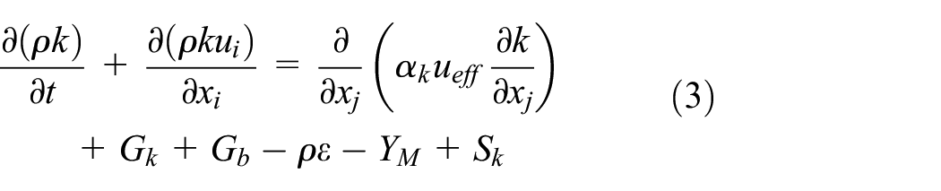
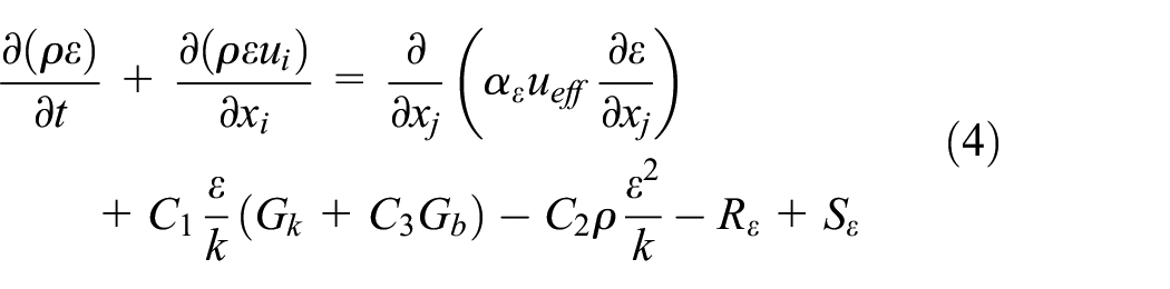
Where ui denotes component of fluid velocity along i direction, k denotes turbulent kinetic energy,
The inlet boundary is mass inlet, the mass flow rate is 0.7 kg/s, the inlet pressure is 170,000 Pa, the temperature is 325 K, the hydraulic diameter is 304 mm, and the turbulence intensity is 2.626%. The outlet boundary is the pressure outlet, the set outlet pressure is 238,000 Pa, the hydraulic diameter is 300 mm, and the turbulence intensity is 2.653%.
The impeller is in high-speed rotating state under the working condition. The rotating reference frame MRF model is used to set the impeller area as the rotating domain, and the angular-velocity is 6188 rpm, and the diffuser and volute are static domain. The blade surface, crack surface, hub surface, shroud surface, and volute surface are all set as wall boundary conditions, and nonslip and adiabatic wall is applied.
The flow is assumed to be steady. The pressure-based steady-state implicit separation solver is applied to the calculation. Re-normalization group (RNG) k-ε model are chosen to be the turbulence model. Energy equation model and standard wall function are applied. Semi-Implicit Method for Pressure-Linked Equation (SIMPLE) is used for pressure velocity coupling. Pressure discretization is standard mode. Momentum and turbulent kinetic energy are discretized in second-order upwind mode. Variable convergence residual is
Entropy production theory
Entropy production is a characteristic parameter that is used to describe irreversible energy loss due to heat transfer and fluid viscosity. The position and magnitude of energy loss can be captured in detail via entropy production theory, and then the internal flow of fluid can be analyzed. The capability of visualized evaluation of energy and aerodynamics characteristics is an advantage of entropy production theory compared with the traditional method. In this research, wall entropy production was not considered.
For turbulent flow, the specific entropy production rate is composed of two parts: one with mean term and the other with fluctuating term.

Where


Kock and Herwig 37 proposed that the turbulent entropy production could relate to the turbulent dissipation rate and the mean temperature.

Results and discussion
Analysis of pressure field in impeller passage
The pressure contour of the impeller passage is shown in Figure 4. The impeller pressure is approximately symmetrically distributed with obvious periodic changes along the circumference, and the air flow is in good condition. Along the flow direction, the pressure increases obviously from the inlet to the outlet, and the pressure gradient changes obviously. There is an obvious low-pressure area at the impeller inlet. The airflow enters the impeller passage and the blades rotate at a high speed in working condition. The pressure gradually increases and the dynamic pressure reaches the maximum at the blade outlet. When the flow enters the diffuser and volute with large circulation area, a certain amount of energy loss is caused due to the vortex impact of the air flow. At the same time, through the pressurization and gas collection of the diffuser and volute, the air flow pressurization effect is obvious. The pressure increases steadily, and the static pressure reaches the maximum value at the outlet of the impeller volute.

Pressure distribution of impeller passage: (a) the static pressure of impeller passage, (b) the total pressure of impeller passage, (c) the static pressure of impeller, and (d) the total pressure of impeller.
It can be observed from the static pressure contour in Figure 4(a) that the static pressure range of impeller passage is 170,421–240,013 Pa. Because the air flow enters the volute area from the diffuser in the counter clockwise direction, there is an obvious high-pressure area at the lower end of the volute throat. The higher radial velocity and smaller space area lead to the high-pressure gas gathering and the static pressure increasing. As a result, the airflow is blocked and the velocity loss is caused, forming a local high-pressure area. It can be seen from Figure 4(b) that the total pressure of the impeller passage increases continuously from the inlet to the outlet, and the total pressure range is 171,595–288,369 Pa. There is an obvious low-pressure area at the impeller inlet and the maximum pressure appears at the edge of the impeller blade outlet. The total pressure loss in the volute is reduced by vortex flow, leading to an unobvious pressure gradient and relatively uniform distribution. When the impeller rotates at high speeds, the airflow at the inlet will collide with the backflow at the outlet of the volute, resulting in high pressure on the blade and affecting the stability of the main flow. Therefore, the pressure and pressure area on the blade near the inlet of the volute are larger than that of other blades. This phenomenon is validated by the low-pressure zone at the inlet. As shown in Figure 4(c) and (d), the pressure gradient of the impeller changes obviously, and the pressure increases with the direction of gas flow, reaching the maximum value at the edge of the impeller blade outlet. Due to the influence of the centrifugal force of high-speed rotation of the impeller, the pressure on the pressure surface of the blade is greater than that on the suction surface. The existence of pressure difference causes the airflow move from the pressure surface to the suction surface, and the secondary eddy flow is formed which increases the generation of low-pressure area on the suction surface and the loss of pressure.
Figure 5 presents the pressure distribution of long and short blades. Along the gas flow direction, the pressure on the blade surface increases gradually from the root of the leading edge to the trailing edge of the blade. The pressure gradient changes obviously and the pressure distribution is more uniform.
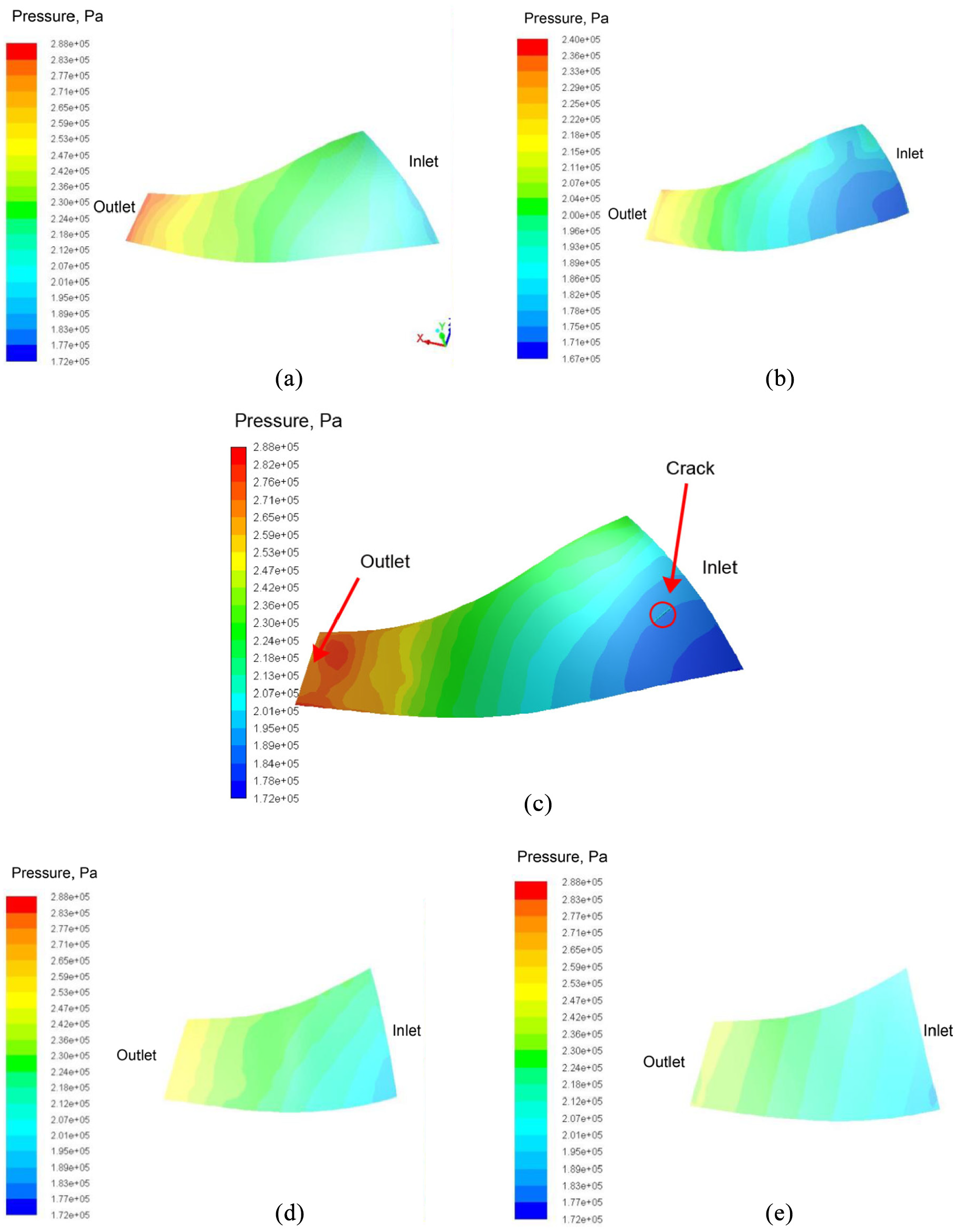
Pressure distribution of impeller long and short blade: (a) pressure surface of long blade, (b) suction surface of long blade, (c) pressure surface of long blade with crack, (d) pressure surface of short blade, and (e) suction surface of short blade.
As shown in Figure 5(a), the pressure range of the pressure surface of the long blade is 187,434–285,852 Pa, in which the minimum value is at the root of the leading edge of the blade inlet, and the maximum value is in the top area of the trailing edge of the outlet. When the airflow enters the impeller inlet, the pressure increases evenly. The high-speed rotation of the impeller and the change of the flow direction cause the airflow impact, forming a low-pressure area of backflow at the inlet of the leading edge, blocking the flow into the impeller, and affecting the stability of the flow field.
As shown in Figure 5(b), the pressure range of suction surface of long blade is 168,939–235,013 Pa, and the pressure distribution is similar to that of pressure surface. With the influence of rotating centrifugal force, the air flow at the leading edge of the blade has negative pressure lower than the inlet pressure at the root. This can easily lead to the formation of local eddy, cavitation, and pitting, causing stress corrosion cracking of impeller blades. Comparing the pressure surface with the suction surface, it can be found that the pressure on the pressure surface is significantly greater than that on the suction surface at the same radial position. Along the moving direction of the air flow, the pressure gradually increases and the pressure gradient changes more sharply.
The pressure distribution of long blade’s pressure surface with crack is displayed in Figure 5(c). Comparing Figure 5(a) and (c), the difference between them is difficult to find out. The length and width of the crack is 20 and 2 mm respectively, while the diameter of impeller is 918 mm. The scale of crack is very small compared with the impeller, so the effect of crack to the interflow of impeller is very weak. It’s difficult to study the effect of crack on the interflow of impeller via traditional analysis.
The pressure distributions of the short blade are displayed in Figure 5(d) and (e), where the pressure range of pressure surface is 195,950–269,175 Pa and the pressure range of suction surface is 186,096–262,930 Pa. The pressure and pressure gradient distribution of pressure surface and suction surface are similar and uniform. The pressure distribution of the short blade is similar to that of the second half of the long blade, which indicates that the main work object of the centrifugal compressor impeller is the pressure surface of the long blade. The role of the short blade is to increase the stiffness of the impeller, improve the distribution of the internal flow field, and reduce the occurrence of vortex between the blades.
The pressure distribution in the crack area of impeller is shown in Figure 6. The pressure range of the crack area is 190,832–195,376 Pa. The overall pressure in the area is large and uniform. Because the impeller at the front end of the area has not been damaged, the minimum pressure is located at the top of the crack front edge. The high-speed rotating centrifugal force of the impeller may cause the vortex phenomenon in the cavity. The backflow of the air in the cavity has a certain blocking effect on the entry of the mainstream, which effectively reduces the high-speed impact of the air flow and forms a local low-pressure area, providing certain protection for the crack area. Therefore, the pressure gradient at the crack front is gentle.

Pressure distribution diagram in crack area of impeller.
Along the flow direction, the pressure increases gradually from the top of the leading edge of crack to the root of the trailing edge of crack, and the maximum value appears at the middle of the crack region and the root of the trailing edge of crack. Under the high-speed impact of rotating air flow, the middle part of the crack area is the main source of air flow in the cavity. Under the impact of centrifugal force and air flow, the pressure generated in the area perpendicular to the crack direction is larger making the crack expand to the depth of the matrix, which is consistent with the fact that the deepest crack is located in the middle of the crack in the actual engineering detection. The air flow gets into the crack cavity and continues to move forward. The impact acts on the matrix at the trailing edge of the crack and produces a large pressure at the root of the crack tip. The double effects of the stress in the middle of the crack and the impact stress at the root of the trailing edge of the crack greatly promote the expansion of the crack area and accelerate the process of stress corrosion cracking of the impeller.
Analysis of velocity field in impeller passage
The velocity distribution of the impeller passage is shown in Figure. 7. The velocity first increases and then decreases along the flow direction of the air. The velocity in the impeller area is symmetrically distributed around the center with obvious periodic changes along the circumference, and the velocity gradient changes obviously. It can be found in Figure 7(a) and (b) that with the high-speed rotation of the blades, the air flow changes from the single axial flow at the inlet to the mixed flow of radial, axial and circumferential direction, and the flow field becomes more complex and violent.

Velocity field distribution of impeller runner: (a) velocity of impeller passage, (b) velocity of impeller, and (c) velocity of impeller meridian plane.
The flow field stability is greatly affected by the centrifugal force and the backflow generated by the high-speed impact of the air, resulting in the uneven distribution of the velocity at the outlet of the impeller blade. The overall speed is increasing, with the speed range of 0.4463–413.4 m/s, reaching the maximum value at the outlet of the suction surface of the blade. As shown in Figure 7(c), the velocity contour of the impeller presents the global state of the air flow after entering the impeller. The velocity of the air flow is relatively stable when air enters the blade channel. Due to the contraction of the inlet flow area and the influence of centrifugal force, the speed at the shroud side is relatively large, and there is an obvious low-speed area at the inlet of the hub side. The flow velocity in the middle section of the blade passage increases obviously. The maximum flow velocity is near the hub side of the blade outlet, and there is an obvious low-speed separation zone at the outlet of the shroud side. The phenomenon of backflow may occur between the blades, which is not conducive to the flow of the mainstream and the formation of the stable velocity field. When the flow enters the diffuser and volute with large flow area, the velocity in the inlet area of diffuser is relatively high. Because part of the kinetic energy is converted into pressure and heat when vortices impact the volute wall, the velocity decreases along the volute channel direction, and reaches the minimum value at the volute outlet. Meanwhile, there are many obvious jet-wake structures at the outlet of the volute, and the velocity fluctuates greatly.
The velocity distribution of the long and short blade of the impeller is shown in Figure 8. It can be observed that the velocity increases gradually from the root of the leading edge of the blade to the trailing edge of the blade along the air flow direction. On the same circumference, because the pressure on the pressure surface is greater than that on the suction surface, the flow velocity on the suction surface is greater than that on the pressure surface. Under the action of high-speed rotation, the air in the blade passage flows from the pressure surface to the suction surface forming secondary vortices. The direction of the vortex and the air velocity on the suction surface are same, so the superposition of two factors increases the flow velocity of the suction surface. With the decrease of the flow area, the velocity vector of the secondary flow in the passage points to the shroud side, and a low-speed recirculation zone finally appears at the shroud side of the trailing edge of the blade, resulting in nonuniform velocity distribution at the impeller outlet.

Velocity distribution of long and short blades: (a) velocity of pressure surface of long blade, (b) velocity of suction surface of long blade, (c) velocity of pressure surface of short blade, and (d) velocity of suction surface of short blade.
As shown in Figure 8(a) and (b), the velocity distribution at the leading edge of the long blade inlet is uniform, and the flow field in the middle section of the suction surface of the blade is complex. There are obvious low-speed regions and reflux vortices, which will affect the flow of the mainstream and cause energy loss. The speed range is 41.3–397.6 m/s, and the maximum velocity is located at the root of the trailing edge of the long blade. As shown in Figure 8(c) and (d), the velocity distribution of suction surface and pressure surface of short blade is uniform, and the velocity gradient variation is not obvious. The velocity range is 95.78–353.2 m/s, and the maximum velocity is located at the root of the trailing edge of short blade. There is small low-speed region and backflow on the suction surface and pressure surface of short blade, which is obviously reduced compared with the same area of large blade. This phenomenon fully proves that the existence of short blade shortens the flow channel width of impeller, effectively reduces the occurrence of reflux vortices, and enhances the internal flow stability of impeller.
The velocity distribution in the crack area of the impeller is shown in Figure 9. It can be observed that the variation of overall velocity gradient in the crack area is small, and the distribution is relatively uniform. The speed range is 162.8–191.3 m/s, and the maximum speed is at the middle of the crack area. With the high-speed rotation of the impeller, the rotating air flows into the crack cavity obliquely. The crack front area is protected by the impeller, and the speed is small and distributed uniformly, so the crack growth trend is not obvious. The velocity in the middle part of the crack is the largest, and the strong impact force produces a certain pressure on the wall surface of the cavity, resulting in a large pressure value in this area, which is consistent with the pressure distribution in the crack area. It is one of the sources of stress corrosion cracking accelerating the further propagation of the crack. The rotating air flow into the crack cavity collides with the air flow entering the crack cavity from the bottom edge of the crack, counteracting part of the kinetic energy, and resulting in the decrease of the air flow velocity. This is consistent with the local low-speed region existing in the lower edge of the crack in the figure. This effect will continue to cyclically act on the crack trailing edge, resulting in a relatively small velocity and little change in the trailing edge of the crack.

Velocity distribution of impeller crack area.
Analysis of temperature field in impeller passage
The temperature contour of the impeller passage is shown in Figure 10. It can be seen from the figure that the temperature of the impeller is symmetrically distributed around the center, and there are obvious periodic changes along the circumference. The minimum temperature appears near the impeller inlet, and the maximum temperature is in the outer wall of the impeller volute and outlet area. The temperature range is 325–430 K, and the variation gradient is not obvious. When the airflow enters the impeller passage, the blade rotates at high speed to do work on the fluid, resulting in a gradual and uniform increase in the temperature of the fluid. At the same time, with the decrease of the flow area in the impeller passage, part of the mechanical energy is converted into gas pressure energy and heat energy, and the temperature continues to rise.

Temperature distribution of impeller passage.
The temperature contour of the blades and crack area are shown in Figure 11. The temperature of the blade inlet root is the minimum, and the maximum temperature is located at the blade outlet. The air enters the diffuser and volute area and swirls is produced because of the structure of the impeller, so part of the kinetic energy is converted into pressure energy and heat energy, and the temperature inside the impeller continues to increase steadily. It is found that the temperature of the blade near the volute outlet changes greatly and a local high temperature area is produced. The temperature of shroud side is bigger than the temperature of hub side. Figure 7(c) shows that the velocity of shroud side is larger than the velocity of hub side which means more heat is produced because of viscous heating. The variation of cyclic temperature difference leads to nonuniform heating of the blades and nonuniform distribution of stress, which is one of the sources of the internal stress of the impeller in service. The temperature changes little in the crack region with the range of 339.2–340.9 K. The temperature variation gradient is not obvious and the temperature distribution is more uniform. High temperature intensifies the deformation of blade and the corrosion reaction rate at the crack tip, accelerates the process of stress corrosion cracking, and make the crack continue expanding forward.

Temperature distribution of blades and crack: (a) temperature of pressure surface of long blade, (b) temperature of suction surface of short blade, and (c) temperature of crack area.
Analysis of entropy production of impeller
Since the crack size is small and the conventional analysis is not intuitive, the entropy production theory is applied to the current research of the crack’s effects on the impeller. The entropy productions of the long blades’ pressure surface with crack and without crack are shown in Figure 12. The Figure 12(a) and (b)’s maximum of entropy production both appear at the inlet of blade, because the high-speed rotation of the impeller and the change of the flow direction cause the airflow impact, forming a low-pressure area of backflow at the inlet of the leading edge, blocking the flow into the impeller, and affecting the stability of the flow field, which is consistent with the pressure analysis. The entropy production turns bigger at the outlet of blade which is because the vortex impact of the air flows exists when the flow enters the diffuser and volute. Comparing the Figure 12(a) and (b), the entropy production suddenly turns large around the crack. It means the energy loss rises, so there is a bad flow happening. The high-speed air gets into the crack, then impacts on the inside of the crack and forms vortex. When the air flow from the crack, the vortex impact of the air affects the flow around the crack and causes energy loss. The presence of crack degrades the compressor’s performance. As the crack grows, the negative influence of crack on internal flow will become apparent, the entropy production will become larger, and the compressor’s performance will be degraded by increased energy loss.

Entropy production of long blades’ pressure surface: (a) entropy production of blade with crack and (b) entropy production of blade without crack.
Conclusions
In this research, the detailed numerical simulation of centrifugal compressor impeller passage, blade and crack area is carried out to explore the internal flow characteristics and crack growth trend of the impeller with crack defects under actual working conditions. The simulation results show that the pressure, velocity, and temperature of the fluid increase along the flow direction, and the maximum values all appear near the trailing edge of the impeller outlet. The velocity impact and pressure accelerate the wear and stress corrosion cracking of the impeller blade, which is consistent with the damage position of the blade under the actual working condition. There is a cyclic temperature difference in blade, resulting in nonuniform heating of the blade and thermal stress. The increment of the entropy production around the crack indicates that the existence of crack makes internal flow performance worse. The maximum stress and velocity in the crack defect region are distributed in the middle section and trailing edge of the crack, and the temperature variation in the crack area is small. Under the triple action of the stress perpendicular to the middle of the crack, the stress corrosion failure at the root tip of the trailing edge and the thermal stress of the blade, the crack propagation is promoted, and the stress corrosion cracking process is accelerated which finally leads to the blade fracture accident.
Footnotes
Appendix
Handling Editor: James Baldwin
Declaration of conflicting interests
The author(s) declared no potential conflicts of interest with respect to the research, authorship, and/or publication of this article.
Funding
The author(s) disclosed receipt of the following financial support for the research, authorship, and/or publication of this article: This research was supported by the National Natural Science Foundation of China (Grant Nos. 51906126, 52006126); the China Postdoctoral Science Foundation (Grant No. 2020M672058); the Ocean Industry Leading Talent Team of Yantai’s Double Hundred Plan; the Key Laboratory of High-Efficiency and Clean Mechanical Manufacture at Shandong University, Ministry of Education.