
Abstract
Machine vision is a key technology to achieve high detection accuracy for the compensation hole parameters of automobile brake master cylinders, which influence automobile safety and parking reliability. As an important part of the automobile brake master cylinder, the compensation hole can play an important role in regulating the brake fluid in the reservoir tank and brake chamber, and its dimensional accuracy and processing quality are strictly controlled. Therefore, determining how to accurately obtain images of the compensation hole is a primary problem in the detection of compensation hole parameters. In this paper, fully automatic equipment for compensation hole detection in automobile brake master cylinders is designed using an image processing algorithm to realize the automatic positioning of the compensation hole and automatic detection of size parameters. Experiments show that the automatic positioning and detection time for the compensation hole is less than 8 s, the detection accuracy of the compensation hole size is higher than ±0.021 mm, and the position detection accuracy for the compensation hole is higher than ±0.045 mm. The compensation hole detection technology proposed in this paper provides high real-time performance and good robustness while meeting accuracy requirements and detection speed.
Introduction
In recent years, the position of the automobile industry in the development of the national economy has become increasingly important,1,2 and one of the main performance indicators of the automobile is the braking performance of the automobile during driving, which directly affects the safety of driving and road traffic operation. Many major road traffic accidents are caused by the long braking distance of the automobile or the sideslip caused by the automobile’s emergency braking. Therefore, how to continually improve the processing quality of the entire automobile brake is the top priority of the entire automobile design and manufacturing engineering industry. The brake master cylinder is the most important component of the entire automobile brake, and its processing quality is essential for the entire automobile brake system. Performance and operation have a great impact. The automobile brake master cylinder is mainly composed of the compensation hole of the brake master cylinder and the brake chamber. The brake chamber is the chamber inside the master hole of the brake master cylinder, which is connected to the brake circuit through the drain hole.3,4 The brake master cylinder compensation hole is a small hole located inside the brake chamber that is used to connect the brake chamber and the reservoir tank. When the automobile is braked or released, the brake chamber and the reservoir tank are adjusted through the compensation hole. The service life requirements of the compensation hole hydraulic brake master cylinder 5 are required to reach 500,000 times under normal temperature working conditions and not less than 120,000 times at 70°C. However, due to the compensation hole and the brake chamber, the processing quality of the penetration is low, and the position and processing size of the compensation hole are difficult to guarantee. Therefore, it is difficult for the brake master cylinder to meet the above requirements. During the driving process of the automobile, the force stepping on the brake pedal controls the piston movement of the brake cylinder rubber piston cup in the brake chamber. When the brake cylinder rubber piston cup moves forward in the brake chamber, the compensation hole is sealed to the brake at this time. The dynamic chamber begins to build up pressure and transmits the pressure to the four wheels to achieve the deceleration effect of the automobile. When the brake pedal is released, the piston drives the brake cylinder rubber piston cup to quickly retract under the action of the return spring, and then the brake chamber a vacuum will be formed, so we replenish the brake fluid in the reservoir into the brake chamber through the compensation hole to reduce the pressure in the brake chamber, so as to ensure that the piston quickly returns to its position. If there is a problem with the position of the compensation hole and the size of the compensation hole, for example, the diameter of the compensation hole is smaller than the standard size, and the position of the compensation hole is larger than the standard size, then it will appear when the driver depresses the brake pedal. Sealing the compensation hole well will cause the pressure in the brake chamber to increase slowly, which will result in a relatively weak deceleration effect of the automobile and a longer braking distance, and when the pedal is released, a vacuum state is easily formed in the brake chamber. Since the size of the compensation hole is smaller than the standard size at this time, the brake fluid in the reservoir cannot be quickly flowed back into the brake chamber in time, and the pressure in the brake chamber cannot be reduced well. At this time, the automobile’s brake pedal will not be able to return to its original position, which will affect the driver to depress the brake pedal again, which poses a great hidden danger to driving safety.
Therefore, precise detection of the position and shape of the compensation hole of the automobile brake master cylinder is required, including detection of the absolute axial distance from the center of the compensation hole to the positioning base surface in close contact with the cylinder body and the size of the compensation hole diameter. The traditional detection method is through contact measurement, which is determined according to the operator’s experience, resulting in low detection accuracy, poor stability, and low efficiency, and it is difficult to meet the detection requirements of modern industrial automation. Later, some scholars developed the CCD-TV spy-bore system, which greatly improved the optical tube inspection method, and the observed images can be saved and recalled afterwards. However, this system has not fundamentally overcome the limitations of the large and bulky equipment and inconvenient operation of the optical tube spy-bore system, and it can only observe the spy bore qualitatively, not quantitatively. 6 Zhang et al. 7 studied the use of a periscope structure (an optical window, an objective lens group and a CMOS camera) in the optical imaging part to replace the endoscope structure by using a stepping motor and a grating ruler, to drive the periscope to move. By a stepping motor and coding, the device cooperates to make the tested piece rotate and move to achieve the purpose of detection. Wang et al. 8 proposed a high-precision non-contact detection method for the compensation hole of the brake master cylinder. The image of the compensation hole was collected by the micro-small endoscopic camera system, the position, size, and shape of the compensation hole of automobile brake master cylinder are detected by human-computer interaction. Although this method has been greatly improved, it still requires the participation of workers. Depending on the technical experience of the workers, the detection of the parameters of the compensation hole will have different effects. Cui et al. 9 proposed a dual-fiber coupling measurement technology on the premise of a detailed analysis of new measurement technologies such as non-contact, compensation and aiming trigger considerations. At the same time, without increasing the hardware cost, this method significantly improves the measurement accuracy, and solves the contradiction between the measurement range, the measurable depth, and the measurement accuracy. Although the above method has improved the measurement accuracy of the compensation hole of the automobile brake master cylinder, there are still problems such as complex measurement algorithm, long measurement time, and large and heavy detection equipment and so on. Therefore, we urgently need a high efficiency, high precision and non-contact detection technology for the shape and position error of the brake master cylinder compensation hole.
Therefore, the main contribution of this paper is to propose a fully automatic automobile brake master cylinder compensation hole detection technology based on machine vision, which integrates light, machine, electricity, and calculation components to achieve high-precision online detection to meet industrial needs. The main measurement range of the detection technology proposed in this paper includes: the main hole diameter of the brake master cylinder is 15–45 mm, the position of the compensation hole is 5–150 mm, and the diameter of the compensation hole is 0.3–1.2 mm. Through the detection method of machine vision, the subjective uncertain factors are avoided, and machine vision provides a non-contact measurement,10–12 it will not produce measuring force on the tested workpiece, no wear and damage, and has a high degree of automation, facilitates simple operation, and provides stability. It has good performance and can realize 100% inspection or sampling inspection of production parts. This system is mainly used in the detection of various types of brake master cylinder compensation holes in the automotive industry. At the same time, this method proposes a good detection scheme for the problem that the small holes on the inner wall of the deep chamber blind hole are difficult to detect. Therefore, it is anticipated that the automatic inspection method implemented by machine vision will be the future direction of the development of automobile brake master cylinder shape and position detection.
Detection systems
The automobile brake master cylinder compensation hole detection system is mainly composed of four parts, which are the electronic control part of the system, the acquisition part of the compensation hole, the lighting part, and the image processing software control part of the system. The system framework is shown in Figure 1, the shape and position detector of the compensation hole of the automobile brake master cylinder is shown in Figure 2:

Framework diagram of detection system.
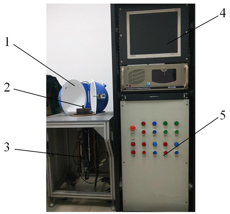
Compensation hole shape and position detector of automobile brake master cylinder.
In Figure 2, 1 is a lighting system, 2 is an image acquisition device, 3 is a motion control part, 4 is an image processing part, and 5 is an electric control cabinet.
Equipment acquisition module composition
The image acquisition part is mainly composed of a computer, a CCD camera, an object imagebi-telecentric lens, an endoscopic light path, a patch LED light source, and an integrating sphere light source. The camera of the image acquisition device is an MV-VS078FM/FC digital color area CCD camera from Weishi Digital Image Co., Ltd. Its resolution is 1024 × 768, the size of the sensor is 1/3”, and the camera frame rate is 30 fps. Because of its small size, high resolution, stable signal, low CPU resource consumption, etc., it is very suitable for image acquisition of the compensation hole of the automobile brake master cylinder. The compensation hole is collected by the matching object image bi-telecentric lens image,13,14 and using endoscopic light path technology to create an image on the target surface of the camera, and finally through a series of image processing algorithms and calculations of the software system, the position and size parameter information of the compensation hole can be obtained, the calculation result is displayed on the screen and the inspection report of the brake master cylinder is printed out through the printing device. At the same time, to avoid sudden power failures of the factory that affect the system, the system is equipped with a UPS stabilized power supply to deal with emergencies. This system mainly detects the compensation hole of the brake master cylinder of model ZDZG-22.2-12.385-1. The brake master cylinder is produced by Jilin Dongguang Aowei Automobile Brake System Co., Ltd. It is mainly applicable to Chery Jietu X70 and other series of automobiles. The main hole diameter of this brake master cylinder is 20 mm, and the cylinder body is full length 133 mm, including two compensation holes. The structure diagram and cross-sectional diagram are shown in Figures 3 and 4.

The physical body of the brake master cylinder.

The cross-sectional view of the brake master cylinder.
Image lighting module
We combine the camera with the object image bi-telecentric lens, cooperate with the annular led active illuminator and the integrating sphere back lighting system, and capture the image of the brake master cylinder in real time when the ball screw is fed with the endoscope. The specific structure diagrams are shown in Figures 5 and 6. Figure 5 is the physical diagram of the annular patch LED active lighting system, and Figure 6 is the physical diagram of the integrating sphere back lighting system. The light source of the integrating sphere lighting system adopts 220 V, 35 W halogen lamps, and at the same time, a uniform diffuse reflection paint is applied to the inside of the integrating sphere to ensure that the illuminance in any direction in the integrating sphere is equal.

SMD LED active lighting system.

Integrating sphere back lighting system.
Equipment control module composition
The control part of the system is mainly composed of a motor, a ball screw, a slider guide, a synchronous toothed belt, and a grating ruler, which realizes the vertical feed movement of the screw and the rotational movement of the brake master cylinder. The physical diagram of the mechanical transmission is shown in Figure 7.

The physical diagram of the transmission mechanism.
In Figure 7, 1 is a synchronous toothed belt, 2 is a grating ruler, 3 is a box body, 4 is a motor, 5 is an endoscope and an image acquisition device, 6 is a slider guide rail, and 7 is a ball screw.
In the actual detection of the compensation hole of the brake master cylinder, it is necessary to measure the compensation holes at two different positions on the upper and lower positions of a brake master cylinder. Therefore, the transmission mechanism that drives the endoscope for linear motion is required to have high stability, rigidity, and the sensitivity of the device itself. So, this paper uses a ball screw as the transmission mechanism of the endoscope to convert the rotary motion of the servo motor into linear motion. In this paper, the FK2505 type ball screw with precision grade of P5 from Tianjin Haite Company is selected. The screw outer diameter is 20 mm, the screw pitch is 5 mm, the step angle is 1.8°, the number of subdivisions is 40, and the rated dynamic load is 13.1 kN, the rated static load is 20.2 kN.
In terms of drive motor selection, we choose two MSMD012G1V servo motors from Panasonic Corporation of Japan as our drive components. MSMD012G1V servo motor is a small inertia servo motor of Panasonic A5 series motor, it has fast response frequency of 2.0 kHz, real-time automatic gain adjustment function and four notch filters, and the MADHT1505 motor driver used in conjunction with the servo motor can well realize motor commutation and motor acceleration and deceleration control.
When detecting the axial distance from the center of the compensation hole to the reference plane of the testing device, we use a grating displacement sensor with the advantages of high precision, high speed, and non-contact to record the relative position of the compensation hole in real time. The LS187 incremental position measuring grating ruler from HEIDENHAIN is selected. Its accuracy grade is ±5 μm, and the measuring length is 140–3040 mm. The LS187 grating ruler has functions such as dustproof and anti-spattering of cutting fluid. It is sealed by flexible strips. And the aluminum housing can well protect the grating ruler and the track from dust, chips, etc. Even in a relatively harsh working environment, it can still be accurately positioned.
In the detection of the shape and position parameters of the compensation hole of the automobile brake master cylinder, the control module of the system mainly realizes the vertical feed movement of the motor with the endoscope and the rotational movement of the brake master cylinder. After the system is powered on, the LED light source inside the brake master cylinder is turned on to illuminate the interior of the brake master cylinder, start the camera, and drive the movement of the motor below to realize the lead screw with the endoscopic light path system into the master cylinder. At the same time, another motor drives the master cylinder to rotate. At this time, the image of the master cylinder can be displayed in real time on the main interface of the computer software.
Device software module
With the enhancement of the stability of WINDOWS10 system, and with the advantages of faster running speed and more security, it has become an inevitable trend of future development. Therefore, the software development of this system is based on the WINDOWS10 system, and Microsoft developed in Visual C++ language, because the MFC basic class library provides a graphical language to design the operating interface of the software, this provides great convenience for the writing of system software. Each function button in the software system is presented on the computer in a graphical manner. On the operation interface, it is convenient for the operator to click and operate.
In regard to the image processing software control part, the core function modules include an image preprocessing module, a calibration module, a result display output module, and an interactive control module with the lower computer. The software adopts modular design, which makes the system easier to maintain and expand and provides flexible design, convenient debugging, and other advantages.
As shown in Figure 8, the software interface diagram is mainly composed of four parts, which are the image display area, compensation hole parameter measurement area, automatic control area, and manual control area. The leftmost end of the software is the image display area, which is used to display the internal image of the master cylinder in real time. In the case of automatic control, the device is initialized first, including the zero-finding of the grating ruler and the loading of the parameter list of the software. The zero-finding operation of the grating ruler is very important, because it directly affects the accuracy of the compensation hole position detection. We set the zero point of the grating ruler at the bottom of the grating ruler. Through the zero-finding command in the initialization, the motor will drive the ball screw with the endoscope to accurately find the zero position of the grating ruler, which is the initial position of the equipment movement, so as to ensure the accuracy of the position of the compensation hole in the automobile brake master cylinder. After the initialization is completed, the position and size of the compensation hole can be detected by the algorithm in this paper. The results will be displayed in the compensation hole parameter measurement area, the master cylinder inspection report can be printed out through the file menu or the print button in the tool bar, and the software can also manually control the vertical movement of the endoscope and the rotational movement of the master cylinder.

Software interface diagram.
Working principle
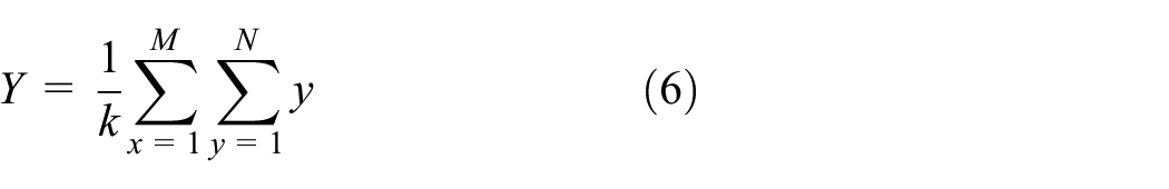
The automobile brake master cylinder compensation hole detection system adopts a fully automatic working mode. First, before testing the product, input the model of the brake master cylinder to be tested, and the technical parameters of the model will be automatically displayed, such as the position parameter of the compensation hole, the tolerance range, compensation hole size parameter, and tolerance range. Then, the manipulator is used to clamp the brake master cylinder and place it in a fixed installation position. Turn on the annular LED light source on the endoscope to illuminate the compensation hole and start the camera. By driving the motor movement, the lead screw with the endoscope light path system enters into the master cylinder. Concurrently, another motor drives the brake master cylinder to rotate. At this time, the internal image of the master cylinder can be displayed in real time on the main interface of the computer software. When the endoscope probe moves to the positioning base surface of the detection device, the position of the grating ruler is recorded as
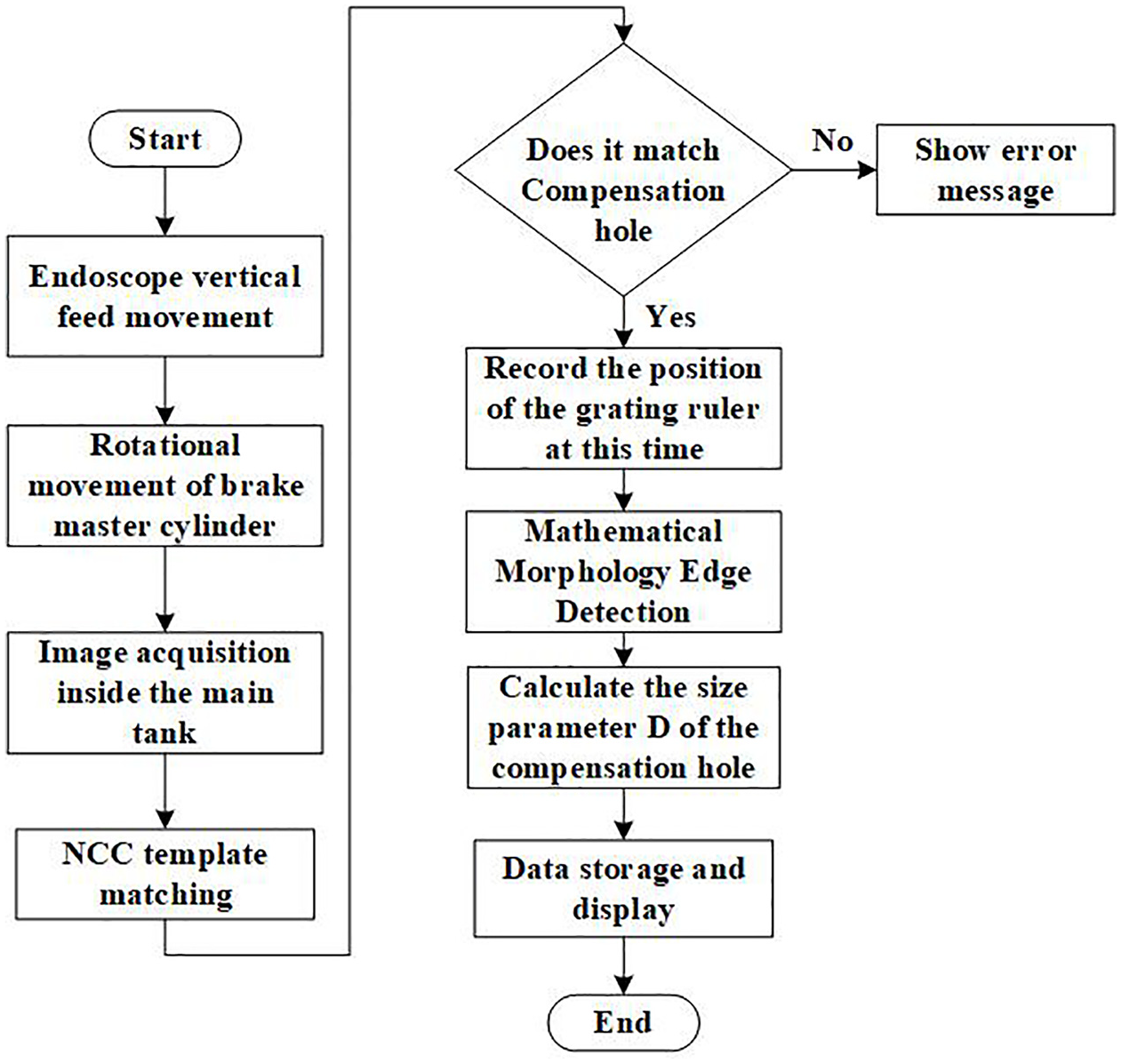
Equipment work flowchart.
Image processing algorithm design
The position of the compensation hole inside the automobile brake master cylinder is detected in real time during the movement, instead of searching manually in the traditional method, which greatly reduces the labor intensity of workers and improves the efficiency of detection. At present, there are many methods to find the hole position and parameter detection in image processing, including the template matching method, global threshold method, local threshold method, mathematical morphology method, etc. The detection effect is verified by experiments in the following.
Template matching
The template matching algorithm 15 is implemented based on the similarity between images, and the template matching algorithm is realized by finding the area closest to the target template in the obtained image. Because the template matching algorithm does not require segmentation and feature extraction of the image, it is just a data operation on the original image, so it can retain the information of the original image. In traditional target detection, template matching is simple in its algorithm. The advantages such as high speed have been widely used.
Template matching is to make a template image and then slide in the original image. By calculating the similarity with the original image, we can determine whether it is similar or the same area. One of the most commonly used calculation methods for template matching is gray value template matching, but gray value template matching is greatly affected by illumination. Considering the situation of illumination change, by subtracting the gray value from their mean value, and then dividing by its unit variance, the image brightness level is not sensitive to illumination change, and the algorithm has strong robustness, which is the normalized cross-correlation algorithm. So that the image brightness level is not sensitive to changes in illumination, and the algorithm has strong robustness, it is the normalized cross correlation algorithm (NCC). The specific formula is as follows:

where
Because template matching has a simple method and a high algorithm efficiency, it can make full use of all the information in the image, so the position of the compensation hole inside the master cylinder can be quickly determined. As shown in Figure 10, we collected the compensation hole as a template and calculated the similarity of the template by calculating the template matching algorithm to determine the position of the compensation hole in the image of the brake master cylinder. Figure 11 shows that after template matching, the position of the compensation hole can be seen from the position of the cross line in the figure, and the detection result is accurate.
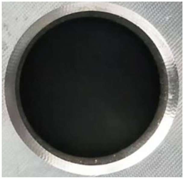
Compensation hole template image.

Template matching result image.
Global threshold segmentation
The image collected by digital camera is converted into grayscale image, which has 256 gray levels. To analysis the characteristics of the image and simplify the calculation, we often convert the grayscale image into a binary image so that the image has only two grayscale levels of 0 and 1, namely, the target image and background. The most important part of image binarization is the determination of the threshold. If the threshold is selected too high, then many target pixels will be misjudged as the background of the image, if the threshold is selected too low, the opposite will happen. At present, there are many techniques for threshold determination in images, such as global threshold segmentation, 16 two-dimensional maximum entropy segmentation, 17 inter-class variance threshold segmentation, 18 co-occurrence matrix threshold segmentation, 19 fuzzy threshold segmentation, 20 and so on.
Among them, the histogram global threshold segmentation method is a relatively simple and common segmentation method using image gray histograms. Because the brake master cylinder lights up the annular LED active illumination, the compensation hole area is darker and the surrounding area is brighter, at this time, the contrast of the target is more obvious and easy to segment. In the histogram global threshold segmentation method, the accuracy of the high and low threshold selection determines the segmentation effect of the edge of the brake master cylinder compensation hole. First, the threshold

Repeat the above steps with

Threshold segmentation histogram.
Global threshold segmentation results.
Local threshold segmentation
By preprocessing the original image, the smoothing template of the image is used for the convolution operation with the original image. The principle of convolution operation is to add the gray value of each pixel in the original image and the gray value of eight neighboring pixels according to the weights. Here we choose that the weights of the eight pixels around the center pixel are equal to 1, and then the average value of the pixel is calculated, and the average value of this pixel is used as the value of the pixel in the new image grayscale values.
The central pixel is the pixel to be processed. The template is convolved with the image, and the convolution result of the gray value in the original image is used as the gray value of the point in the new image. For the point on the boundary, since it does not have eight neighborhoods, no processing is performed. Then, the difference between the calculated and smoothed image and the original image is obtained, and the large changes in the image are extracted by the threshold method, which is the approximate area where the compensation hole is located. Several filtering conditions allow easily obtaining the location of the compensation hole. The experimental results are shown in Figure 14.

The effect of image local threshold segmentation.
As can be seen in the Figure 8, the compensation hole found by the image local threshold segmentation algorithm has a slightly better detection effect than the global threshold segmentation algorithm, but there are problems such as thick edges and disconnection between the edges of the image, the detection effect still cannot meet the demand.
Mathematical morphology
Mathematical morphology is considered as a discipline based entirely on mathematical set theory. It is a powerful means to analysis and describe geometric morphology. In 1964, French Matheron 21 and Serra 22 in terms of geometric-related technical research results, mathematical morphology has been introduced into the field of image processing, and a multimedia image processing system based on mathematical morphology has been designed and developed. There are four basic calculation methods of mathematical morphology: dilation, erosion, and opening operation and closing operation.
For a target image

The specific algorithm of expansion is as follows: use

Dilation diagram: (a) original image, (b) structural elements, and (c) image after operation.
The erosion – uses vector subtraction on the set elements to merge the two sets.

The erosion algorithm is similar to the dilation algorithm, but the result of the erosion algorithm is to reduce the image target. The specific process is shown in the Figure 16, where Figure 16(a) is the original image, Figure 16(b) is the structural element of mathematical morphology, and Figure 16(c) is the image obtained after mathematical morphology. It can be seen that the contour of the target element in the image after the mathematical morphology is eroded. Compared with the original image, the target contour becomes smaller.

Erosion diagram: (a) original image, (b) structural elements, and (c) image after operation.
Through the acquired image of the brake master cylinder, first use the mathematical morphological dilation operation on the image and then perform the erosion operation on the original image. By subtracting the eroded image from the dilated image, the internal edge image of the master cylinder can be obtained. By selecting the edge, the position of the compensation hole edge is extracted, and the edge detection effect is shown in the figure.
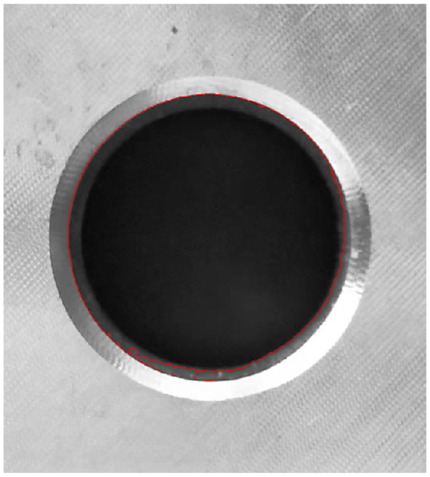
It can be seen from Figure 17 that the edge detection of mathematical morphology is significantly better than the global threshold segmentation method and the local threshold segmentation method. The edge of the mathematical morphology is described by red lines, which coincides well with the actual edge of the compensation hole, and the edge contour is fine. There is no obvious discontinuity, so it is suitable for the size detection of the compensation hole in this paper.

Mathematical morphological segmentation effect diagram.
Algorithm detection method this paper
The above describes the detection methods of various compensation hole image edges. The edges of the image can be detected by the above algorithms, but the scope of application, anti-noise performance and positioning accuracy of the detection algorithm are different. Among them, NCC correlation template matching is simple in calculation and high in accuracy. Because of the similarity between the internal texture of each automobile brake master cylinder and the shape of the compensation hole, the confidence score after matching is more ideal. Threshold-based segmentation methods, such as the global threshold segmentation method and the local threshold segmentation method, are all susceptible to illumination, and the detection effect is not good, which limits the use of detection equipment. The edge extraction algorithm based on mathematical morphology can not only accurately extract the edge of the compensation hole but also has no obvious discontinuity on the edge, and the edge contour is thin. Therefore, this paper proposes a combination of the NCC template matching extraction method. First, the NCC template matching algorithm is used to accurately extract the area of the compensation hole during the movement of the endoscope acquisition system, and then the parameters of the compensation hole are detected by the mathematical morphology algorithm.
The image of the compensation hole is acquired by the system’s endoscope acquisition device, and the area where the compensation hole is located is accurately extracted by the NCC template matching method. Since there are always some abnormal points and noise points in the image of the compensation hole image, which affects the accuracy of the contour, through mathematical morphological dilation and erosion operations, abnormal points and noise points can be removed to smooth the image and extract the edge of the compensation hole effect.
Considering the symmetry of the hole, the center coordinate of the compensation hole can be obtained by the centroid method. Defining the area of the target in the image is the number of pixels occupied by the target, that is, the number of pixels contained in the boundary of the region, denoted by

The radius of the compensation hole is the average distance of each point on the compensation hole from the center of the circle. If the number of boundary points is
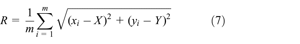
Among them
Different algorithm detections.

Experiment and verification
This paper takes ZDZG-22.2-12.385-1 model brake master cylinder compensation hole detection as an example. The theoretical distance between the first compensation hole and the second compensation hole from the reference plane of the detection platform is 40.34 and 111.47 mm, the position detection accuracy is ±0.045 mm, the theoretical diameter of the two compensation holes is 0.7 mm, and the diameter detection accuracy is ±0.021 mm. The ball screw drives the endoscope into the system from the beginning. It takes approximately 8 s to move the inside of the master cylinder to the bottom of the master cylinder. And the detection time is required to be within 1 min.
The algorithm in this paper is applied to the real-time detection of the compensation hole of the brake master cylinder of an automobile, and the position of the compensation hole in the master hole of the brake master cylinder is successfully detected through the NCC template matching algorithm. Extract the region centered on it with the region of 400 pixels in length and 400 pixels in width, that is, the region of interest from the upper left corner
Compensation hole position and size detection.


Measurement error of the compensation hole position of the master cylinder.

Measurement error of the compensation hole size of the master cylinder.
The position and diameter of the compensation hole calculated by the above eight sets of experiments indicate that the difference between the average value of the two compensation hole positions and the actual size calculated repeatedly is less than 0.008 mm, and the error fluctuation of each position measurement is within ±0.02 mm. The difference between the average diameter of the compensation hole and the actual diameter is less than 0.002 mm, and the fluctuation of the single-size measurement error is also within ±0.02 mm. Therefore, the detection method in this paper meets the requirement that the compensation hole position accuracy be less than 0.045 mm, and the size detection accuracy of the compensation hole is less than 0.021 mm, which meets the testing requirements.
Finally, this paper algorithm and several other single compensation hole edge detection algorithms are respectively applied to the standard brake master cylinder compensation hole and compensation hole parameter detection with oil contamination, to determine the advantages of this algorithm in detection accuracy, detection efficiency and robustness. Several single edge detection algorithms include: Method 1: whether the compensation hole is detected by the human eye and manually select three points on the compensation hole from the image. The principle of determining the center of the circle from the three points that are not on the same straight line, and calculate the size of the compensation hole parameter. Method 2: the compensation hole is detected through human observes and uses the global threshold segmentation method to extract the edge of the compensation hole, and calculates the size parameter of the compensation hole. Method 3: the compensation hole is detected through human observes and uses the local threshold segmentation method to extract the edge of the compensation hole, and calculate the size parameters of the compensation hole at the same time. The algorithm in this paper: NCC template matching algorithm is used to automatically detect the position of compensation hole, and then the edge algorithm of mathematical morphology is used to detect the size parameters of compensation hole. Due to limited space, here we record the average value of 10 tests of each algorithm in Table 3. The specific experimental data are shown in Table 3.
Compare the detection accuracy and detection efficiency of different detection methods.
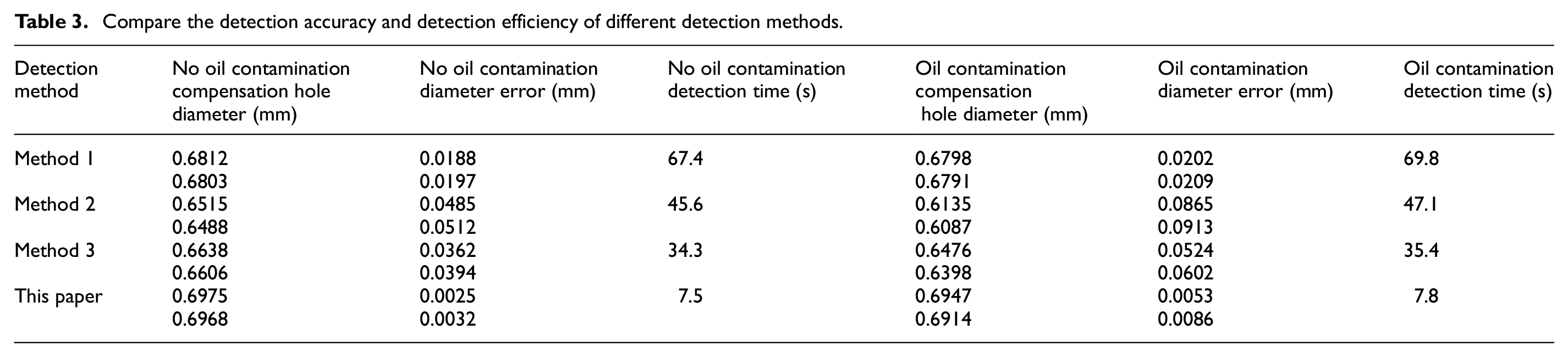
From the statistical data in Table 3, we can see that in method 1, when detecting the size of the compensation hole through human-computer interaction, although the detection error meets the accuracy requirements when there is no oil contamination or oil contamination interference in the compensation hole, the error is still large, and the detection time exceeds the detection time required by the system. Although the two detection methods of 2 and 3 meet the requirements in terms of detection efficiency, there is a lack of detection accuracy. The detection algorithm proposed in this paper can drive the endoscope through the ball screw, and the time from entering the brake master cylinder to completing the parameter detection of the two compensation holes is about 8 s, and it can meet the requirements of high-precision detection with or without oil contamination interference. Therefore, compared with other detection methods, the detection method proposed in this paper can achieve high-efficiency and high-precision detection of the compensation hole of the automobile brake master cylinder, and has good robustness.
System error analysis
There are unavoidable system errors in any experimental system. What we have to do is to reduce the measurement error as much as possible. To achieve this goal, it is necessary to detail the source of the error and the proportion of various errors in the total error analysis. The following is an analysis of the main error sources of the experimental system.
Optical system error
Since the camera lens in this paper is an object-side image-side bi-telecentric lens, its magnification is a constant magnification, and the magnification is 0.75, so there is no optical magnification error. Therefore, the optical error
Image distortion error
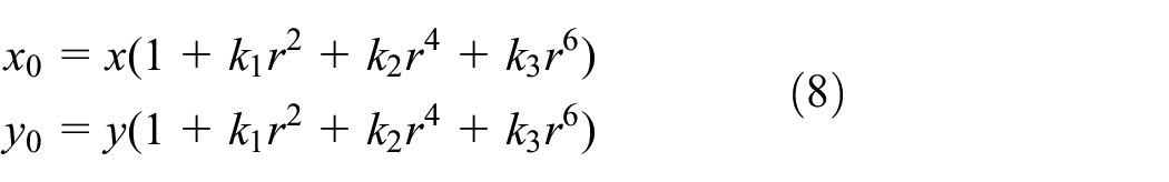
In the formula,
Mechanical system error
Since the system transmission adopts a ball screw, there is bound to be a lead error in the transmission process. The screw pitch of this system is 5 mm, the step angle is 1.8°, the subdivision number is 40, and the lead is 5 mm. Then, the lead error

In the formula,
Systematic random error
System random error refers to the influence of measurement results due to the fluctuation of small factors during the measurement process. The random error
In the detection of the shape and position parameters of the compensation hole of the automobile brake master cylinder, due to the feed movement of the lead screw, some irregular vibrations must be produced. We can only suppress these vibrations as far as possible, but cannot eliminate them. However, through the experimental verification, it is found that these vibrations have little influence on the detection error of the shape and position parameters of the compensation hole, which can be ignored.
Because all objects have characteristics of thermal expansion and contraction, the size of the automobile brake master cylinder will be affected under different temperature environments, which will affect the parameter detection of the compensation hole. Therefore, the temperature during detection is not clear. Parameter detection is meaningless. In our country, the standard temperature is defined as 20°C, but the actual working environment is generally not, so it will certainly affect the measurement results. The specific influence formula is as follows:

In the formula,
According to the analysis of the above system error, the total system error

where
Conclusion
The edge location method that combines the NCC template matching method and mathematical morphology overcomes the problems of low accuracy and poor stability of a single algorithm in edge detection. The application of this method replaces the traditional method of positioning and measuring through manual observation. Experiments show that it takes less than 1 min to detect the position of the compensation hole in the brake master cylinder, the position detection accuracy of the compensation hole is higher than ±0.045 mm, and the size detection accuracy is higher than ±0.021 mm. In this paper, the brake master cylinder detection system is based on the compensation hole position and size detection accuracy of the image processing algorithm. After a large number of experiments, the reliability, detection speed and accuracy are shown to meet the requirements of use.
Footnotes
Handling Editor: James Baldwin
Author contributions
ZC proposed a compensation hole automatic detection algorithm that combines NCC template matching and mathematical morphological edge detection for this paper. ZC, DH wrote the main manuscript text and completed most of the experimental content. HH prepared all the figures and tables. Cao completed part of the experiment and carefully verified the format of the manuscript. All authors have read and agreed to the published version of the manuscript.
Declaration of conflicting interests
The author(s) declared no potential conflicts of interest with respect to the research, authorship, and/or publication of this article.
Funding
The author(s) disclosed receipt of the following financial support for the research, authorship, and/or publication of this article: This work was supported by the National Key Research and Development Program, Development of Major Scientific Instruments and Equipment (2017YFF 0105304), Key Research and Development Project of Jilin Province Science and Technology Development Plan (20200401117GX), Jilin Province Provincial Industrial Innovation Special Fund Project (2018C038-4).