
Abstract
This paper states that there might have around 1000 small size business jets (until nine occupants) flying across the world equipped with flow control and regulating shut-off valves that uses hot wire anemometer devices to regulate massflow rate from the bleed airflow to supply the air-conditioning and pressurization systems. However, these valves present low reliability in the field. The purpose of this paper is to evaluate the implications of a flow control and regulating shut-off valve with a non-intrusive airflow measurer device under the perspective of fluid mechanics. The Venturi technology that is commonly used technology, given its construction simplicity, precision, and broad use in the industry, is selected to substitute the flow control and regulating shut-off valves with hot wire anemometer of the mentioned small size business jets applications. This paper has adopted a numeric simulation approach utilizing the ANSYS-CFX computational fluid dynamics software to verify both the differential pressure at the Venturi device and its correspondent mass flow rate to supply the air conditioning systems of some small size business jets, considering the mass-flow rate as requested by the FAA certification requirement (0.55 lb/min per occupant). This paper shows that a mass-flow rate control and regulating shut-off valve with a Venturi device, of 1 inch and β of 0.67, is compliant with the minimum fresh air flow requested by the FAA certification requirement to operate in some small size business jets. Besides that, the software ANSYS-CFX is also effective to support the engineering analysis of flow field characteristics inherent to the applications of internal compressible flow. The numeric simulation utilizing the ANSYS-CFX computational fluid dynamics software outlined herein can lay the basis for further research related to the design of a flow control and regulating shut-off valves with a Venturi device.
Keywords
Introduction
It is estimated that there might have around 1000 small size business jets flying across the world equipped with flow control and regulating shut-off valves with hot wire anemometer devices, as primary and solely air flow measurer device used to regulate the bleed airflow, of both air-conditioning and pressurization systems. It is recognized that the hot wire anemometer device is mostly utilized in static applications destined to laboratory tests, experiments, or industrial applications that require constant recalibration, and it is not commonly used in measurement of higher Mach bleed airflow as in aircraft applications. 1 Additionally, the hot wire anemometer technology presents complexities and fragilities inherent to its design 1 when combined with the premature removals as reported by field operators, explains the impact in the reliability issues of these small business aircraft. 2
The accurate measurement of the bleed airflow rate is indispensable for a viable and proper operation of an aircraft environmental and propulsion systems. In addition to this, the flow control and regulating shut-off valve needs to comply with its reliability requirement as per contract in order not to affect the field operation costs with lower MTBF (mean time between failure). The flow control and regulating shut-off valve proper operation guarantees a steady mass flow rate into the cabin to avoid the undesirable ear cabin-bumps or abnormal cabin pressure fluctuations (ft/min) that affects passenger comfort.3,4 It also maintains a smooth and constant engine bleed air extraction (lb/min) within the pre-established design level for the entire flight duration, 5 thus, not affecting fuel consumption either.
It is also acknowledged that the flow control and regulating shut-off valve are designed to perform its intended function under any foreseeable operating condition as per certification requirement from FAR regulation, thus its reliability factor is also a key parameter to guarantee its expected lifetime in operation, and thus, to improve competitiveness of the business jets operation. The employment of the term competitiveness in the business jets daily-basis operation refers to no pilot reports and no unscheduled maintenance action that leads to AOG’s (Aircraft on ground). These causes aircraft owner’s dissatisfaction, because are related to non-predictable costs, dispatchability issues, and most critically enquires about the product performance.
It is reasonable to assume that the technology employed in hot wire anemometers construction1,2,6,7 when installed in a flow control and regulating shut-off valve that operates in an aircraft bleed system environment 8 does not comply with its reliability numbers (MTBF) in real operation.
It is acknowledged that the bleed airflow is susceptible to contaminants, water condensation, and even pebbles of ice during some flight phases. The design criteria for a flow control and regulating shut-off valve assembled in air conditioning systems of some small size business jets9,10 considers this harsh environment. Therefore, the Venturi design with its non-intrusive airflow measurer device assures a robust operation also in compliance with its reliability requirement. Besides the fact that the Venturi measurer device in terms of installation requirement is suitable to the massflow rate shut-off valve, and, it is also an extensively studied and used device in worldwide engineering applications with viable costs both for manufacturing and maintenance.11–13
Tables 1 to 3, summarize the major characteristics of each massflow rate measurer device herein described in order to justify the study of an alternative technology for the substitution of a flow control and regulating shut-off valve with hot anemometer by a flow control and regulating shut-off valve with Venturi for some small size business jets.2,6
Basic technical data – application/standards.

Basic technical data – limitation.

It is believed that for a single set-point mass flow reading at a time the disadvantages are not applicable.
It does not work properly when the work fluid contains contaminants and water from condensation.
Basic technical data – advantage/disadvantages.

Contaminants, water from condensation or ice pebbles, and the employment of soldering, respectively contribute to imprecise readings and low reliability.
The general relevant topics listed in the next bullets summarize some of the main design characteristics of the hot-wire anemometers described in Tables 1 to 32,6,7:
The miniature size of the wire assembly that is in contact with the fluid flow;
Assembly difficulties due to the employment of soldering between the interface of the hot-wire anemometer probe and Wheatstone bridge electronic circuit board;
The direct impact of contaminants and water from condensation or ice pebbles causes the wire to provide temporary flow rate misreading, and it can also contribute to the soldering rupture, thus part failure;
The dynamic forces caused by the airflow itself can stretch the wire thus contribute to the soldering rupture.
The flow control and regulating shut-off valves are typically installed at non-pressurized regions of the aircraft. 8 The flow control and regulating shut-off valves need to comply with certification requirements as per FAR regulations to deliver the due mass-flow rate supply to the occupants, and, be reliable on its operation.
Figure 1 portrays a division in which the bleed system or pneumatic system distributes the compressed air that comes from the engine compressor outlet port to the users, such as the air conditioning, pressurization, and anti-ice systems with controlled temperature and pressure throughout the entire aircraft operation. The air conditioning system controls air temperature and the bleed air flow rate to guarantee a habitable living condition inside an aircraft, in accordance with the cabin temperature control and minimum ventilation certification requirements as per FAR regulations. 14
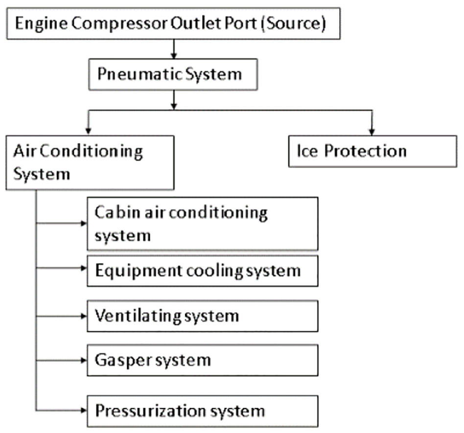
Diagram of the bleed supplied systems.
Figure 2 shows the location where the flow control and regulating shut-off valve is usually installed in a typical air conditioning system architecture of some small size business jets. 8

Schematic of air conditioning system (one engine side) small business jets.
The air-conditioning system basic architecture for a small size business jet shown in Figure 2 consists of a typical closed loop control system for the cabin temperature regulation, in which the pressure controlled thermal energy comes from the engine compressor (hot) and fan (cold) outlet ports. Then, the bleed airflow is distributed by the pneumatic lines passes by the heat exchanger and then goes to the temperature modulating valve to be adjusted to hot, cold, or mixed configuration. Finally, the air passes through the flow control and regulating shut-off valve and goes to the low-pressure distribution ducts inside the cabin. The temperature-modulating valve has a hot and a cold inlet ports for the airflow to be mixed and distributed into the cabin. These butterflies are positioned 90° one from another, in order to suitably allow the air mixture to the aircraft operation/flight phase according to the air-conditioning digital controller. The ambient (cabin and cockpit) and duct (cabin and cockpit) temperature sensors along with the pilot’s manual temperature adjustment encompass the closed loop digital control of the air conditioning system. The ECS (Environmental control system) digital controller acts on the temperature modulating valve whenever the pilot adjusts the temperature of the cabin until the ambient temperature senses that its temperature level is equivalent to the pilot’s adjustment or when the aircraft operation demands bleed air temperature change. The duct temperature sensor is typically a monitor device responsible adjust the temperature modulating valve in case the temperature trespasses a certain design limit level 8 (limited by 100°C due to the composite air-conditioning duct).
The schematic of Figure 2 also shows the VCS (Vapor cycle system), Condenser, and Evaporator that are commonly used in small size business jets to cool down the cabin temperature on ground when there is higher outside air temperatures. 8
Figure 1 also shows that the pressurization system is a sub-system of the air conditioning system, in which it has its own independent exhaust airflow regulation system that must also be compliant with the certification requirement by the FAR regulations.
The flow control and regulating shut-off valve has its own independent closed loop control system destined to the mass flow rate regulation to comply with the certification requirement by FAR regulation. 8 This valve has two functions into one component. It measures the massflow rate through a measurer device (hot-wire anemometer) which generates a proportional current to actuate the bi-directional motor that causes the motion of the butterfly valve which consequently adjusts mass flow rate until it achieves the desired set-point (zeroing a Wheatstone bridge circuit).
The flow control and regulating shut-off valves with Venturi flow measurer device, as described in this paper, has the same basic schematic as shown in the Figure 3 (except the airflow measurer device).

New flow control and regulating shut-off valve – Venturi (study version).
The flow control and regulating shut-off valve has a single butterfly valve to adjust the bleed airflow used for cabin pressurization, minimum fresh air flow supply, and equipment cooling. The valve has a bi-directional gear motor to rotate the butterfly valve to a position based on an output from an analog electronic controller linked to a Wheatstone bridge circuit. This controller of the flow control and regulating shut-off valve senses the mass flow variation of the bleed air using a Venturi device plus a temperature sensor at the exit of the valve as per Figure 3, which is the only difference when compared to the hotwire anemometer valve. Then, it processes these data from the differential pressure and temperature sensors in the PCB and sends a proportional input signal to the analog motor gear. This controller of the flow control and regulating shut-off valve constantly performs its duty of modulating the butterfly valve to a certain position where it maintains the mass flow rate within the design set-point. Both hot-wire anemometer and Venturi valves share the same functionality architecture.
This article presents the results of the numeric analysis based on a CFD analysis in order to obtain the flow field characteristic inherent to values of the differential pressure on the Venturi with its respective massflow rate.
Some articles15–17 demonstrate relevant details about the Venturi technology that validates its cost benefit use due to its construction simplicity, airflow stability, low pressure drop, and the inherent regime of choked compressible flow. The article from Mzad and Elguerri 15 also demonstrates through laboratory measurements of compressible flow fluids from convergent – divergent nozzles that the chocked flow at the throat limits the mass-flow rate, and just downstream the throat there are also supersonic shock waves similar to the results herein presented in this article.
Figure 4 shows an overall framework that illustrates the interconnectivity of the three main elements, pre-processor, solver, and post-processor, within the CFD analysis. 18

The interconnectivity functions of the three main elements within a CFD analysis framework.
Description of the problem
Pre-processor (geometry and mesh)
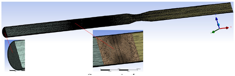
Figure 5 shows the pre-processor step of the CFD analysis that encompasses the preparation of the CAD geometry and the construction of the mesh.

Fluid domain flow control and regulating shut-off valve – Venturi (ANSYS-space claim).
The geometry is basically the CFD fluid domain (on the center) that comes from the valve CAD model (on the top). The CFD fluid domain (on the center) is the volume of the airflow path. This volume is extracted automatically from the inner volume of the valve CAD model by the ANSYS SpaceClaim. Hence, the components from the exterior of the valve CAD model are not used in the CFD fluid domain.
Figure 5 also shows the mesh (on the bottom) that consists of the discretized fluid domain used by the algorithms of the numerical calculation of any CFD analysis.
Solver
Transport equations + physical model
The universal form of the transport phenomena equation that governs the problem herein presented is expressed as equation (1)18,19:

Where,
Table 4 shows the mathematical formulation for the fundamental physics principles of the transport equations and the physical model through the conservation of mass (Continuity equation), momentum by the Newton’s second law (Conservation of momentum equation), and energy by the first law of thermodynamics (Conservation of energy equation) for a very small control volume of CFD applications. The two equations
Expressions for the generic equation.
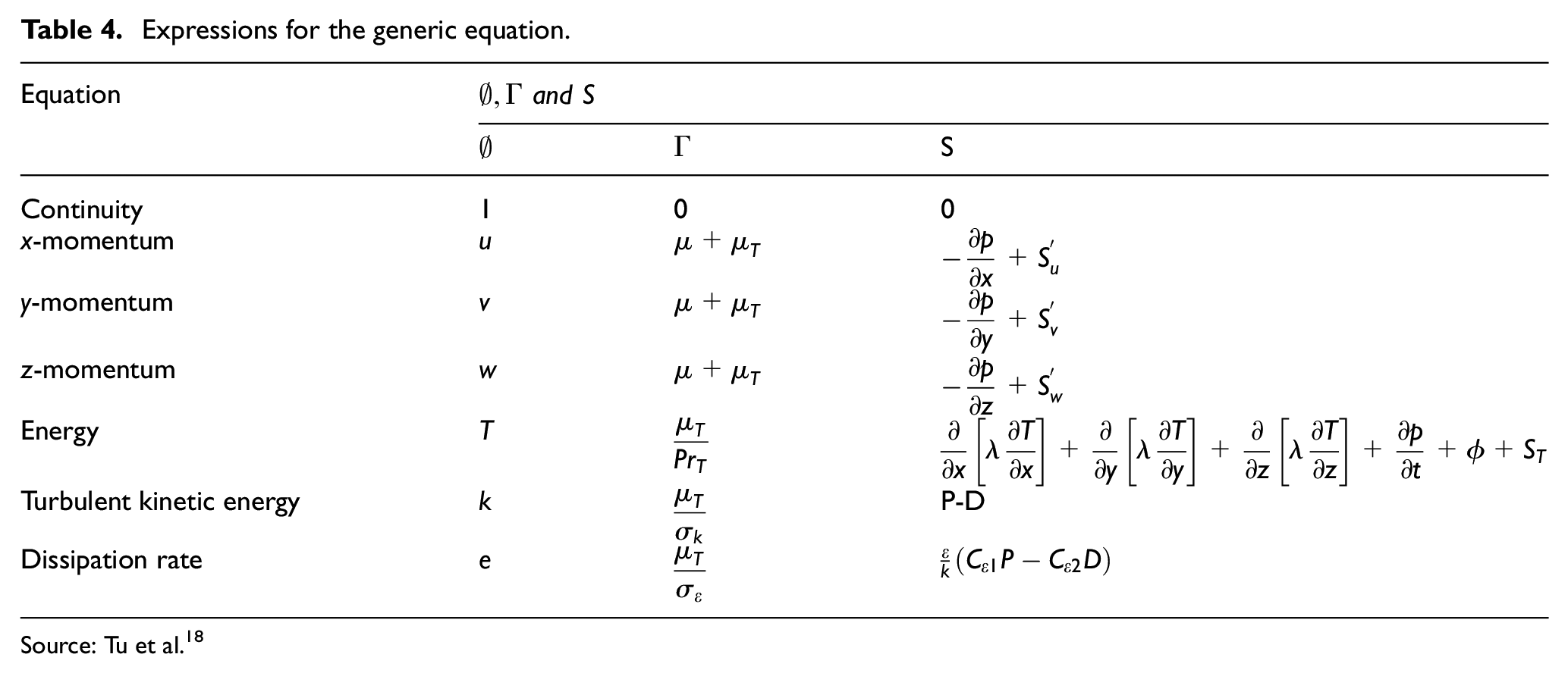
Source: Tu et al. 18
The source of momentum equations
For compressible flow condition, such as herein presented, when temperature significantly affects the density, it could be addressed through equations of state, as per equations (2) and (3), in which it provides the association between energy equation with the mass and momentum equations.19,20,22


Solver settings
ANSYS-CFX uses an algorithm to solve the numerical calculation that depends on the element-based finite volume method that involves the discretization of the fluid spatial domain using the mesh composed by innumerous tiny cells. The mesh is basically the group of innumerous tiny finite volumes, or cells, within the fluid spatial domain that are used to conserve the quantities such as, mass, momentum, and energy as cited in the previous section20,23,24 and solve it numerically.
The fluid flow domain distributed into these tiny finite control volumes, or cells, serve as boundaries for the transport of fluxes and species. The algorithms from the ANSYS-CFX solver allows the partial differential equations to be substituted by algebraic equations, and then, be numerically solved on each tiny volume from the discretized mesh of fluid flow domain. The discrete approximation developed for CFD are mostly based on series expansion approximations of continuous functions (such as Taylor series).20,24,25
The objective of this work is to obtain the massflow rate with its correspondent differential pressure at the ports P1 and P2 of the Venturi device, within a certain range of pressure ratio between the inlet and outlet of the valve based on estimation of ground (0 ft) and maximum ceiling (40,000 ft) operations of a small business jet.
Methodology
Geometry and meshing
Figure 5 the geometry of the Venturi device of the shut-off control valve is generated from the ANSYS SpaceClaim, and its design criteria is based on the ISO-5167-4 26 standards, the convergent side from ØD (pipe) to Ød (throat) has 21°, the length of the throat has 1x Ød, and divergent side from Ød (throat) to ØD (pipe) has 15°. The pipe lengths upstream the Venturi is 12 times its ØD (pipe), and downstream the Venturi is 10 times its ØD (pipe). The geometry of the Butterfly valve, part of the shut-off control and regulating valve, is also designed based on ISO-10631 27 standards adopting the concentric design criteria.
Figure 6 shows the mesh fluid flow domain of the Flow control and regulating shut-off valve – Venturi (intermediate with number of elements of 5,634,006), also mentioned on Table 5. For cells optimization purpose, it is used the sweepable bodies methodology of mesh construction with the size and quality of 5,634,006 elements, 3,689,794 nodes, and an average skewness of 0.10496 with maximum metric of 0.74999. This complies with the typical global and local configuration controls of mesh construction, that aims at quality criterion of skewness (below 0.75).21,25
Finite volume control discretized – fluid domain – Venturi (ANSYS-mechanic).
Boundary conditions to ANSYS CFX.

There are about 25 prism layers on the wall in order to obtain a possible y+ within the viscous sublayer. 23 An average y+ value close to 3 along the wall of the valve is then obtained in order to best capture the behavior of the boundary layer and the aerodynamic phenomena that exist in that convergent-divergent device region. 5
The fluid domain of the analysis presents an extended inlet and outlet, beyond the limits of the valve from Figure 3, that does not affect the results, as CFD good practices, to avoid introducing errors early in the solver calculation, or even to cause the backward-facing step issues.21,25
The mesh independency study is also another relevant approach of CFD good practices to ascertain whether or not the mesh construction is suitable to the boundary conditions imposed to the intended CFD analysis.21,23,25,28 Table 6 shows five mesh constructions from the fluid domain to evaluate the differences in results of pressure and massflow in relation to the boundary conditions of the CFD analysis. The mesh independency study reveals that the intermediate mesh demonstrates to be adequate, with errors of less than 1% when compared to the ultra-refined mesh of 14,892,772 elements and considering the boundary conditions of this CFD analysis.21,23,25,28
Mesh independency study.
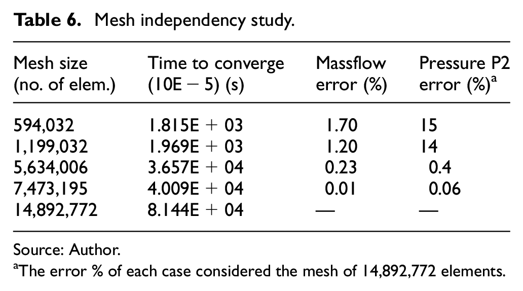
Source: Author.
The error % of each case considered the mesh of 14,892,772 elements.
Design points/boundary conditions (pre-processing set-up)
The cabin back pressure employed on the CFD analysis of this article encompasses both the ground and in-flight scenarios of a typical aircraft operation, as stated by the ASHRAE 29 Standards section 13. This means that on ground at sea level the absolute pressure inside the cabin is 14.7 psia, and in flight, at its maximum operation ceiling of 40,000 ft, the cabin pressure is limited to an altitude of 8000 ft, which means that the absolute pressure inside the cabin is 10.92 psia.
The atmospheric pressures both on ground (sea level) and in-flight (40,000 ft) operations are respectively 14.7 and 2.58 psi.
The gauge pressure from the air-conditioning ducts of an aircraft type as described in this article is usually between 29 and 35 psig.29,30 Moreover, this article adopts a more conservative approach and uses a gauge pressure of 20 psig from the air-conditioning ducts.
Hence, the absolute pressure ratios between the duct and the cabin, both on ground and in-flight operations, are presented on Table 6.
Table 7 shows an airflow temperature of 100°C that cross the massflow rate shut-off valve, energy equation model is total energy, and turbulence model is k-ω SST for the boundary conditions of the CFD analysis.
Boundary conditions to ANSYS CFX.

Maximum cabin pressure altitude as per certification requirement FAR regulation of 8000 ft. 29
Table 8 shows the other relevant parameters to compose the boundary conditions of the CFD analysis from this article.
Boundary conditions to ANSYS CFX.

It is used where kinetic energy effects become significant with gas flows which the Mach number exceeds 0.3. 25
Solver set-up
The solver control settings for the analysis herein presented typically are 5 :
Advection scheme: High resolution;
Turbulence numeric: High resolution;
Convergence control: 1–1000;
Fluid timescale control: Auto timescale, conservative, 1;
Convergence criteria: RMS, 1E-5 with target of 1%.
Results (post-processor)
Ground case
The computed data obtained from the simulation of mass-flow rate is 0.108081 kg/s (14.28 lb/min) and the delta pressure at the Venturi device is 91,493 Pa (13.26 psi).
A visualization of the general structure of the flow field at the cross-section of the valve for Mach, velocity, pressure, and density are presented in Figures 7 to 10.

Mach and velocity fields – butterfly valve fully open position.

Mach number contours with complex shock waves structure – zoomed view.

Static pressure and density flow fields – butterfly valve fully open position.

Numerically obtained pressure and Mach distributions along the inflow and outflow of the valve.
Figure 7 shows that the flow is subsonic at the converging section, then it becomes chocked at the throat (area A*) of the Venturi where it is allowed the maximum mass-flow rate that can pass through the throat. Then according to a De-Laval nozzle theory, in the diverging section of the Venturi the field flow that consequently turns into supersonic is accelerating between the throat and just upstream of the shock wave based on Mach increase due to local value of A/A*. At last, the field flow turns back into subsonic further downstream of the valve outlet pipe.22,31
Figure 8 is a magnification view of Figure 7 that shows a supersonic field flow with complex shock waves, due to sudden perturbations of the density, velocity, and pressure, just after the exit of throat toward to the divergent section until downstream the tube of the valve. This type of converging diverging device is generally intended to produce supersonic flow near the exit plane.5,22,31 There is also a small low speed recirculation zone located just downstream the diverging the section of the Venturi, this was captured by the Steady Reynolds-Averaged Navier-Stokes RANS SST model.
The variation of the Mach number and the velocity from Figure 7 are proportionally correspond to variation of the flow field at the cross-section of the valve for pressure and density as per Figure 9.
Figure 10 shows that the pressures and Mach distributions were numerically obtained by the common generating centerline along of the inflow and outflow of the valve body. When the fluid approaches the vicinity of the butterfly valve, the pressure increases, and the Velocity decreases due to the wall dynamic interaction. It also shows that pressure varies proportionally to the velocity throughout the convergent-divergent Venturi. 31
41,000 ft case
The computed mass-flow rate is 0.070869 kg/s (9.37 lb/in) and the delta pressure at the Venturi device is 59,727.7 Pa (8.66 psi).
A visualization of the general structure of the flow field at the cross-section of the valve for Mach, velocity, pressure, and turbulence are presented in Figures 11 to 13. Although the sonic regime is yet observed at the throat of the Venturi, the intensity of Mach, velocity, pressure, and density are slightly less severe when compared to the ground case, due to the fact that the pressure ratio Pduct/Pcabin for the 40 kft case is proportionally less intense. The flow field behavior observed in the Figure 13 resembles the characteristics described as per Wright et al. 32 for cases between 0.40 and 0.50 (Pexit/Pentry) with complex shock wave patterns.

Mach and velocity fields – butterfly valve fully open position.

Static pressure and density fields – butterfly valve fully open position.

Mach number contours with complex shock waves structure – zoomed view.
Figure 14 the same flow field pattern as Figure 10, however the magnitude is slightly different due to the peculiarity to the boundary conditions from 40 kft case. 32

Numerically obtained pressure and Mach distributions along the inflow and outflow of the valve.
Conclusion
This paper demonstrates that it is possible to substitute the flow control shut-off valves technology from hot wire anemometer to Venturi with 1 inch and B = 0.67 in order to be installed in some small size business jets. The computed mass-flow rates from both simulations, ground 0 and 40 kft cases, are compatible to the minimum fresh air flow demand for small business jets as per FAA regulations of 0.55 lb/min per occupant even in a conservative scenario of 20 psig of pressure gauge from the air-conditioning duct.
Additionally, the supersonic field flow characteristic observed in the CFD analysis is inherent of the boundary conditions imposed, therefore, noise might also be an issue. This observation is corroborated by the publication from Tebib et al. 5 and Wright et al. 32 that also reveals that noise might also be a challenge for this type of valve, thus probably a muffler for noise suppression might also be evaluated as part of the installation.
Future work
For a future work, the construction of a prototyping valve, for laboratory testing purposes, allows the validation of the CFD model in the context of real gas flow measurement data, as well as provides means to verify the noise characteristics inherent to the field flow characteristics. This testing campaign also aids in the evaluation of how the installation of a temperature sensor at the outlet of the valve in fact affects the response time of the butterfly valve, thus the precision of the mass-flow rate to achieve its target value or set point.
Footnotes
Handling Editor: James Baldwin
Declaration of conflicting interests
The author(s) declared no potential conflicts of interest with respect to the research, authorship, and/or publication of this article.
Funding
The author(s) received no financial support for the research, authorship, and/or publication of this article.
Availability of supporting data
All available data are part of the manuscript.