
Abstract
Additive manufacturing as a major component of the “fourth Industrial Revolution” is getting more and more attention. Friction additive manufacturing technology (FAM) is a subdivision of additive manufacturing technology. Because of its solid-state characteristics, deposition by FAM shows better mechanical performance than other technologies such as powder bed fusion technologies. This paper presents a state-of-the-art survey on the development of FAM in three categories: (i) Friction stir additive manufacturing; (ii) Friction surfacing additive manufacturing; (iii) Metal powder assisted additive manufacturing. The underlying principles, process parameters, microstructure, mechanical properties, and existing problems are described and discussed in detail.
Introduction
Additive Manufacturing (AM) is a deposition technology that converts 3D data models into entities. Materials are accumulated in 2D planes and then increments into 3D shapes, 1 which is also called 3D printing technology. 2 The technology was originated in the 1980s, 3 and rapidly evolved with numerical tools (CAD, CAM, simulation software, etc.) 4 and modern technology (directed energy deposition,5–9 material jetting, 10 sheet lamination 11 ). Compared with subtractive manufacturing, additive manufacturing saves a lot of materials, and overcomes the problems of tubular processing and right-angle processing. 11 The geometry, programming and other aspects also show excellent advantages. This technology is suitable for a variety of materials, such as ceramics, metals, and composites,12–15 and application fields, including aerospace, biomedical engineering, plastics industry, automotive industry,12,16,17 etc. It is also known as a key component of the “Fourth Industrial Revolution.” 18
According to ASTM F2792 Standard, 19 additive manufacturing technology is divided into seven categories, as shown in Figure 1. Friction Additive Manufacturing (FAM) is a subdivision of sheet lamination (SL). Although the fusion-based laser additive manufacturing 20 and selective electron beam additive manufacturing 21 are widely used, defects such as pores and cracks resulted from material fusion are inevitably produced, which seriously affect the mechanical performance. High-power input will cause problems such as metal vaporization and excessive splashing, and the consumption cost is too high.22–24 Inclusions and non-uniform structures in the microstructure,7,25 residual stress, and deformation generated during the process are also the factors that affect the performance of the sample.26,27 In order to avoid liquid-solid phase transition, the solid-state deposition technology of FAM was developed, which is more environmentally friendly and has strong interlayer diffusion bonding and higher deposition rate. 11

A list of additive manufacturing classifications.
A patent by White 28 proposed the idea of feeding plates, strips, or silk. It was not applied until 2006 that Airbus published the first report on the use of friction stir technology for additive manufacturing components. 29 After more than a decade development, the research of FAM has gradually matured and a variety of processing methods have been derived. In this paper, a state-of-the-art survey on FAM technology was carried out in the aspect of three subcategories: (i) Friction stir AM, (ii) Friction surfacing AM, (iii) Metal powder assisted AM. The principles, process parameters, microstructure and mechanical properties, as well as problems and challenges of these technologies are analyzed and summarized.
Friction Stir Additive Manufacturing
Principle
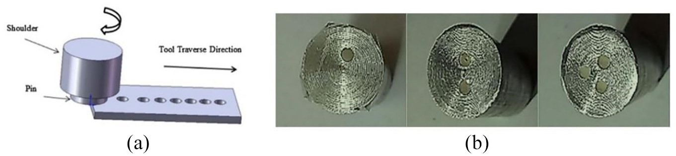
Friction stir additive manufacturing is based on friction stir welding (FSW) and friction stir processing (FSP) technology.30,31 The process diagram is shown in Figure 2. The plate is placed on top of other plates and clamped, a stirring tool with a pin is inserted into the plate at high rotation speed. The friction between the tool and the workpiece produces heat to soften the surrounding material. Compared with FSW, FSAM uses a longer stirring pin, the length of pin exceeds the thickness of the plate. As the stirring tool moves, the material along the path continues to plasticize, and a firm bond is formed after cooling.32,33 This process continues with more plates added, until the required height is achieved. The friction stir AM inherits the advantages of FSW technology, including high efficiency, safety, no waste gas, high quality.34,35 It can control the structure of microstructure through incremental reheating and remixing.36,37

Schematic of multilayer friction stir additive manufacturing process. 38
Process parameters
Sharma et al. 39 mentioned in a study that appropriate process parameters directly affected the quality of fabricated materials. The process parameters of friction stir AM include rotation speed, welding speed, shape, and size of tool pin. A summary of the process parameters used in the literature was tabulated in Table 1.
A summary of friction stir additive manufacturing.

Rotation speed
The rotation speed determines the friction speed between the tool and the materials. The faster the friction speed, the faster the heat generation rate. If the temperature is too high or too low, pores, cracks, and other defects would occur. Palanivel et al. 29 carried out four-layer friction stir AM with 1.7 mm thick sheets of WE43 alloy at two different speeds of 800 and 1400 rpm. Figure 3 shows the cross section of the specimen at 1400 rpm. Hooking defects were observed at the bonding interfaces. Cavity were found at the bottom of the sheet. This was caused by insufficient plastic flow of the material. Cracks were also observed in the heat affected zone. Mahto et al. 51 found that rotation speed had an insignificant effect on hook defect in the two-layer AA6061-T6 thin plate friction stir experiment. The sample at high rotating speed had a deeper mixing zone due to greater plastic deformation. 50 Cao and Jahazi 40 conducted a two-layer friction stir AM of AZ31B-H24 magnesium alloy at the rotation speed of 500, 750, 1000, 1500, and 2000 rpm. It was found that joint strength initially increases with increasing tool rotational speed but decreases with further increase, as shown in Figure 4. The variations of average grain size and hardness in the stir zone with tool rotational speed was presented in Figure 5. With a higher tool rotational speed, the grains in the stir zone become larger and the hardness decreases.

Defects in multilayer friction stir additive manufacturing (Material: WE43). 29

Effect of tool rotational speed on tensile shear load (Material: AZ31B-H24). 40

Effect of tool rotational speed on grain size and hardness in the stir zone of the top sheet at the mid-thickness (Material: AZ31B-H24). 40
Traverse speed
The traverse speed also has an important influence on the mechanical properties and microstructure of the sample. Slow traverse speed leads to excessive temperature accumulation in a short displacement. 52 When the tool travels too fast, the heat generated is not enough to soften the material in the forward direction, and defects such as gaps will occur. Roodgari et al. 48 used low carbon steel sheets (ST52) as substrate and the interstitial-free (IF) steel sheets as additive plate to conduct the two-layer friction stir AM under different welding speeds of 40, 70, and 100 mm/min. It can be seen from Figure 6 that no vertical material flow took place from the IF steel sheet to the St52 sheet or vice versa. The specimen had the most uniform and finest grain distribution at a traverse speed of 40 mm/min, buy the hardness and tensile strength had the highest value at a moving speed of 70 mm/min, as shown in Figure 7. This was due to more oxides produced at the interface in the specimens with 40 mm/min than those with 70 mm/min interface. Li et al. 49 carried out friction stir AM for AZ31B magnesium plate at 40, 80, 120, 160 mm/min traverse speeds. It was found that the traverse speed had little effect on the hardness. But when the traverse speed decreases, the tensile properties gradually increase and then decrease. As shown in the Figure 8, the maximum tensile-shear loads were obtained at various traverse speed.

Microstructure at different traverse speeds: (a) 40 mm/min, (b) 70 mm/min, and (c) 100 mm/min (Material: IF steel). 48

Performance at different traverse speed: (a) hardness and (b) ultimate tensile strength (Material: IF steel). 48

Tensile-shear loads of joints at different welding speeds (Material: AZ31B Mg). 49
Tool shapes
Different shapes of stirring tool have different stirring effects, leading to different fluidity in the material and the different grain size in the plasticized material.53,54 Common shapes of tool pin include thread, tapper, polygon, and so on. 55 As shown in Figure 9, Zhao et al. 56 utilized five different tool pin shapes, concave pin (T1), conical pin with three concave arc grooves (T2), cylindrical pin with three concave arc grooves (T3), flared pin with three concave arc grooves (T4), and cylindrical pin (T5). The influence of tool pin on the bonding characteristics of AM was tested at the rotational speed, 800 rpm, and traverse speed, 100 mm/min. The cross-sectional macrostructures of specimens manufactured by different tools were presented in Figure 10. It was concluded that the T2 and T5 are not applicable to the friction stir AM process owing to the very poor material mixing across the bonding interface. In contrast, the convex featured tool (T1) and the tool with three concave arc grooves (T3 and T4) caused good mixing of materials across the interface, especially the latter.

Different types of tool pin: (a) convex featured pin, (b) conical pin with three flats, (c) cylindrical pin with three concave arc grooves, (d) flared pin with three concave arc grooves, and (e) cylindrical pin. 56
Macro cross sections of the specimens manufactured by different tools: (a) T1, (b) T2, (c) T3, (d) T4, and (e) T5 (Material: Al-Li alloy). 56
The size of the tool includes the length and diameter of the pin and the diameter of the tool shoulder, which affect the heat generation in the process. Sahu and Pal 57 using Taguchi Grey Relational Analysis (GRA) to study the process parameters of friction stir for AM20 magnesium alloy. It was found that shoulder diameter was the most influential parameter on weld qualities. Andrade et al. 58 studied the effect of shoulder size on heat generation with diameters of 10, 12, and 16 mm. It was found that the maximum temperature increased with the increase of shoulder diameter. In order to produce a sufficiently deep softened material zone, friction stir AM required a deeper stirring pin than normally used in conventional friction stir welding, even longer than the thickness of the plate sheet.
Microstructure
In the friction stir AM process, the thermal cycle during each additive process has an impact on the microstructure of the accumulated materials. Therefore, the microstructure in each layer is different in the friction stir AM process. 59 Yuqing et al. 42 carried out a nine-layer friction stir additive for 5 mm AA7075-O sheet. The material in center stirred zone was fully mixed showing no grooves and holes. The layer interface was nearly invisible. He et al. 38 conducted 12 layers of AM for 4 mm thick 7N01-T4, as shown in Figure 11. Inhomogeneous microstructures were found in the stir zone, and the dominant feature of the macrostructure is the repetition of the overlapping zones between two adjacent layers obtained a nearly complete cross-section. In addition, they found that the color of the upper layer was obviously darker than that of the lower layer, and observed defects such as kissing bond at the bonding interface.

Macro- and micro-structures of the cross sections: (a) macrostructure of the build, (b) microstructure of layer 7 and layer 8; (c, f, and g) hook and kissing bond defects, (d) band structure, and (e) microstructure of the overlapping interface region (Material: 7N01-T4). 38
In terms of grain distribution, due to the state of high shear and high temperature process, the grain has a strong refinement. 60 Yuqing et al. 42 observed the microstructure of different layers with optical microscopy. By comparison, it was found that the microstructure in the substrate was coarser banded along the direction of rolling. As a result of plastic deformation and thermal cycle in the additive process, the dissolution, coarsening, dynamic recrystallization, and other phenomena occurred. Dynamic recrystallization led to equiaxed fine grains in the stir zone. The grain size in the non-overlapping interface regions increased from top to bottom owing to that the material at the bottom had to experience more thermal cycle and longer static annealing. He et al. 38 presented grain characteristics in the top, middle, middle-overlapping interfaces, and in the bottom regions of the build. The grain size and grain boundary angle were measured as shown in Figure 12. The average grain sizes increased in the order: overlapping interface (2.48 μm) < top (2.86 μm) < middle (3.02 μm) < bottom (3.30 μm). It was concluded that the reinforced cooling could be an effective way to control and optimize the microstructures.

The different Grain boundaries: (a) top, (b) middle, (c) overlapping interface region, and (d) bottom (Material: 7N01-T4). 38
Mechanical properties
The defects in microstructure, grain size distribution, and intermetallic layer have significant effects on the strength of the samples. 61 According to Hall-Petch relationship 62 as below. The finer the grain, the more grain boundaries, the stronger the ability to block dislocation movement, the better its performance.


where,
Hardness and strength are inversely proportional to grain size. The strength depends on solute elements, grain boundaries, dislocations, and the second phases to block the dislocations. These microstructure variables are strongly affected by the processing route and the welding parameters. 29 Based on the above equation and the grain size distribution, it can be inferred that the hardness and tensile strength of the upper layer manufactured by friction stir additive are higher than those of the lower ones. Zhang et al. 37 established a new integrated model by combining the precipitate evolution model, Monte Carlo method and finite element model. The simulation results showed that re-heating and re-stirring can make the grain more finely distributed, thus improving the hardness and yield strength. After data processing, the relationship between hardness and yield strength is as follows:

where,
Hardness
He et al. 38 tested the microhardness at different positions in the vertical direction, as shown in Figure 13. The overall trend of the hardness decreased from top to bottom, owing to the influence of the multi-pass thermal cycles during the AM process. Yuqing et al. 42 measured hardness of AA7075 build in both vertical and horizontal directions, as shown in Figure 14. Similar trend in the vertical direction can be found as He et al. 38 While in the horizontal direction, the hardness varied slightly and almost symmetric along the centerline.

Hardness distribution at different depths (Material: 7N01-T4). 38

Horizontal hardness distribution (Material: AA7075).
For AM process of dissimilar material plates, Li et al.
49
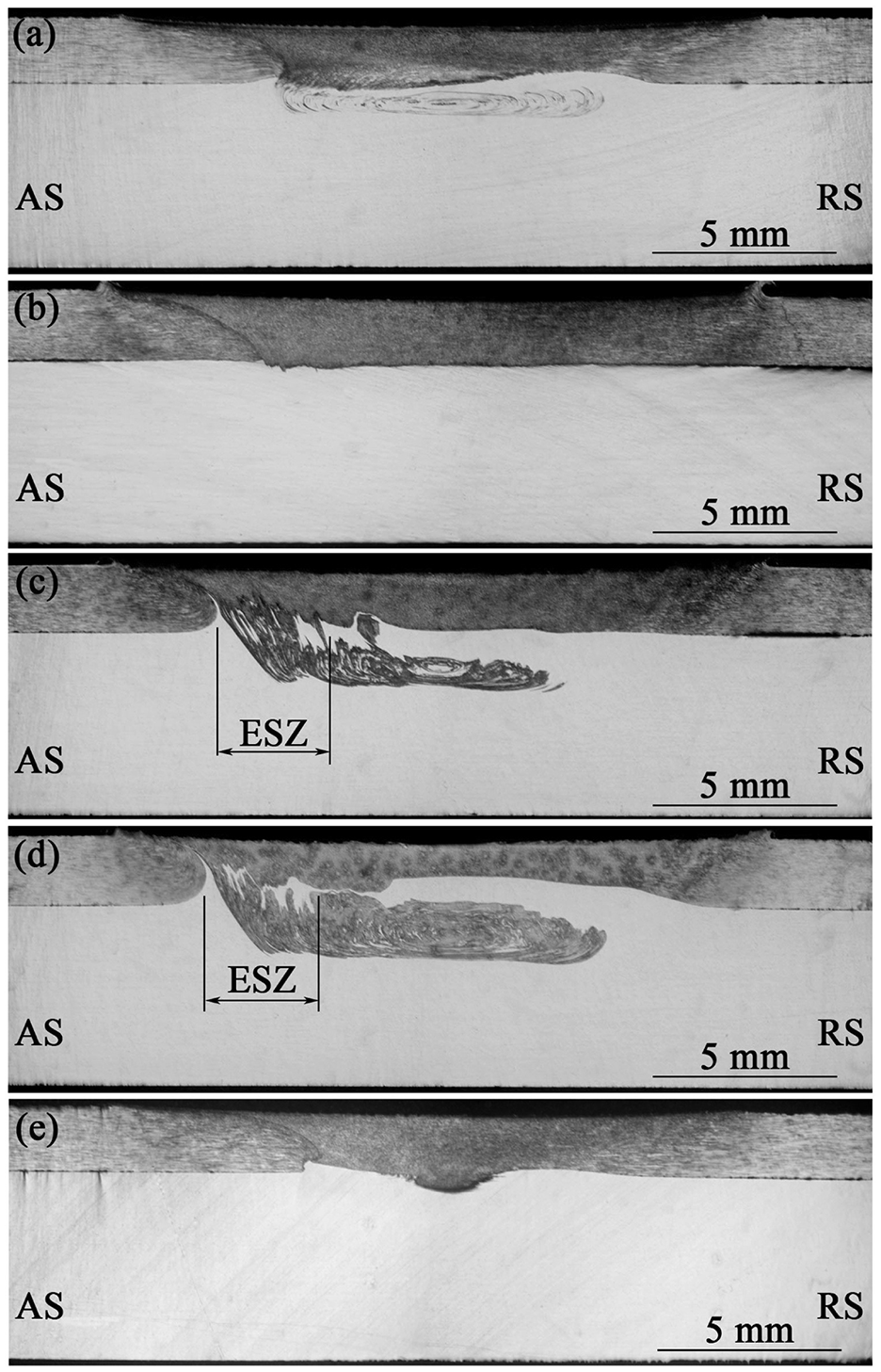
added AZ31B Mg plates to Ti-6Al-4V alloys plates. In the horizontal direction, the hardness of the stirring zone in the upper plate was slightly lower than that of the base material, as shown in Figure 15. In the vertical direction, there was a sharp change in the bonding interface since the hardness for two base materials were significantly different. The mixing of dissimilar materials may cause higher hardness than the two base materials. Guan et al.
46
place 3 mm 6061-O Al plate on 3 mm T3 Cu plate for friction stir processing. It can be seen from Figure 16 that a sudden increase in hardness as a result of intermetallic compounds formed at the interface such as

Hardness distributions along: (a) middle thickness of upper Mg alloy and (b) joint center line in thickness direction. 49
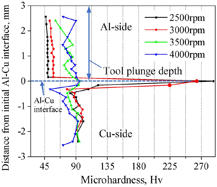
Hardness profiles measured across the Al-Cu interfaces along the tool axis line. 46
Tensile properties
Yuqing et al. 42 carried out tensile tests with samples cut from different positions of the build material. The ultimate tensile strength was presented in Figure 17. The ultimate strength was 278 MPa at the top and 231 MPa at the bottom, while the elongation exhibited the opposite trend, with the largest value of 14.8% at the bottom and 10.4% at the top. Compared with the base material, the tensile strength was significantly improved and the elongation was slightly decreased. The distribution of ultimate tensile strength gradually decreased from the top to the bottom.

Ultimate tensile strength and elongation (Material: AA7075).
Friction surfacing additive manufacturing
Principle
The principle of friction surfacing AM is shown in Figure 18. Through the high-speed friction between the consumable rod and the substrate, enough heat is generated to plasticize the rod material. Because the temperature gradient of the substrate and the rod is different, the plasticized material cools faster on the side of the substrate, thereby forming a coating. 63 The heat dissipation at the rod is slow, which leads to excessive plasticization of the rod and flashes under the action of axial force. 64 Through the lateral movement of the consumable, a continuous additive material is left on the substrate. Repeating the processing on the first layer of additive samples, the height of the additive material increases. 65 Friction surfacing AM has been used as an industrial forming technology. 66 Its application fields include surface processing, 67 aircraft manufacturing, 68 manufacturing metal composites, 64 and so on.

Schematic of friction surfacing additive manufacturing process.
In recent years of research, a more novel form of friction surfacing has appeared. As shown in Figure 19, Phillips et al. 69 used a special stirring tool for friction surfacing. A square through hole was machined in the middle of the mixing tool to feed the material. There are four tear-like bulges around the bottom of the square hole. Perry et al. 70 also conducted a similar study, with two small spherical protrusions at the bottom of the square hole. With the stirring effect of the protrusions, a non-planar interface was created, and the effective combination of the deposition material and the substrate was observed on the non-planar interface, as illustrated in Figure 20. During the experiment, the material underwent continuous dynamic recrystallization, which led to significant grain refinement and better performance.

New type of friction surfacing: (a) cross section schematic of the beginning of the AFS-D process where the tool plunges into a substrate while spinning at a predetermined rotational speed, (b) the tool is then raised to the layer height during which time an actuator drives a solid, or powder, feedstock through the tool as the tool traverses across the substrate, producing a layer, (c) at the completion of a layer, the spindle raises to the next layer height and repeats the process to build consecutive layers, (d) photograph of the actual AFS-D process applied to AA6061, and (e) image of the teardrop featured tool. 69

Material flow process at the protrusion (Material: AA2024). 70
Process parameters
Friction surfacing process parameters include rotation speed, moving speed, axial force, rod diameter, and offset. 71 Table 2 summarizes the process parameters used in previous research works.
A summary of friction surfacing additive manufacturing.

Rotation speed
In friction surfacing, the rotation speed determines the friction speed and strain rate, thus affecting the heat generation. Higher rotation speed leads to higher temperature, softening consumables more excessively, which makes it easier to generate higher flash and smaller maximum-diameter of rod. This affects the contact area between the consumable rod and the substrate, and reduces the width and thickness of the coating. However, at high speeds, the distance between the annular rings on the surface of the surfacing layer becomes smaller and the surface becomes smoother. Tokisue et al. 73 uses a 5 mm thick 5052 P-34 aluminum alloy plate as the substrate, and a 20 mm diameter 2017 BE-T4 aluminum alloy bar as the consumables. Under the conditions of friction pressure of 30 MPa and feed speed of 9 mm/s. As shown in the Figures 21 and 22, when the rotation speed increases, the thickness gradually increases while the width gradually decreases, when the tensile strength increases to a certain strength, it does not increase any more, and the deposition efficiency gradually decreases.
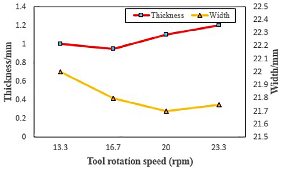
Width and thickness of the sample (Material: BE-T4).

The tensile strength and deposition efficiency of the sample (Material: BE-T4).
The high heat caused by the high rotation speed will also affect the coarsening of the grains. Fitseva et al. 68 conducted friction surfacing of Ti-6Al-4V at 300–6000 rpm. At low rotating speed (400 rpm), the grain refinement was achieved. At high rotational speed (3000 rpm), high temperature led to coarsening of grains. However, the dynamic recrystallization generated by surface friction counteracted grain coarsening, such that the grain size was controlled within a certain range. The process temperature did not increase when the rotating speed continuously increased, there was a limit value for the process temperature. The hardness didn’t vary much when the rotation speed increased, as shown in Figure 23.
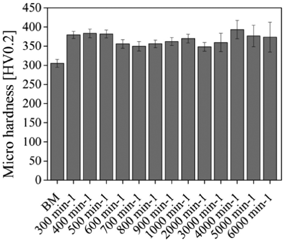
Average hardness of layers at different RPM (Material: Ti-6Al-4V). 68
Traverse speed
The traverse speed mainly affects the thickness of surfacing layer. Vitanov et al. 89 developed a decision support system using rule-based and modeling techniques. With the help of the database and the model of the relationship between some process parameters and state variables, the temperature, torque, and processing time are monitored in real time to predict the quality of the added material. By comparing the experimental data, it is found that the thickness of the added material decreased with the increase of traverse speed. The increase of thickness led to the decrease of bonding performance. Due to the reduced bonding time.
Due to the significant influence of rotation speed and traverse speed on the additive sample, the combined research of the two is also very important. High rotational speed and high welding speed will produce compressive residual stress (lower hardness), low rotational speed and traverse speed will produce tensile residual stress (higher hardness), the latter has weaker adhesion between the surfacing layer and the substrate. 87 The response surface method was used to analyze the process parameters of friction surfacing 75 as shown in Figure 24. It was found that when the velocity ratio (the ratio of the feed rate to the welding speed) was constant, the increase of the rotation speed will reduce the quality of the sample. After optimization, it can be found that the sample performance was the best when the rotation speed was lower and the velocity ratio was higher. The analysis of variance (ANOVA) found that the velocity ratio was the main factor affecting the machining process.

Graphical study of multiple responses (coating thickness, coating regularity, and bond strength) to determine the optimal range of input variables (Material: Stellite6). 75
Axial force (feed rate)
Sakthivelu et al. 88 used stainless steel 304 (consumable rod) on the surface of the ductile iron plates (substrate) for friction surfacing addition manufacturing. The experiment was designed by L9 orthogonal array. It was found that the axial force had the greatest influence on the hardness and bending strength. Sahoo et al. 90 proposed an analysis method of multi response criteria into the Taguchi method for the friction surfacing AM of AISI 316 stainless steel and EN24 medium carbon steel. It was also found that axial force had the greatest influence on the width and thickness of the layer. Sakihama et al. 72 deposited 5052 P-H34 aluminum alloy consumable rods on 5052 P-H34 aluminum alloy substrate. With the increase of the axial force, the width and thickness of the sample did not change much. The tensile strength and surfacing efficiency decreased with friction pressure, as shown in Figure 25.

Surfacing efficiency and tensile strength of the sample (Material: 5052 BDS-F).
Rod diameter
In friction surfacing AM, the diameter of the consumable rod directly affects the width of the additive sample. The size of the diameter determines the processing contact area. Sahoo et al. 85 tested different diameters (14, 18, 22 mm) of 6063 aluminum rods on AISI 316 stainless steel plates. As shown in Figure 26. The larger the diameter, the higher the maximum peak temperature. In the bending test, the peeling at the interface occurred with an applied load of 2 tons at 90° bending angle for the 14 mm diameter rod. But for specimens with 18 and 22 mm rods, no peeling or crack was found at 90° bending angle. The larger diameter the rod, the higher the bending strength. The maximum bending load was 3.2 ton with 120° bending angle for the 22 mm rod specimen.
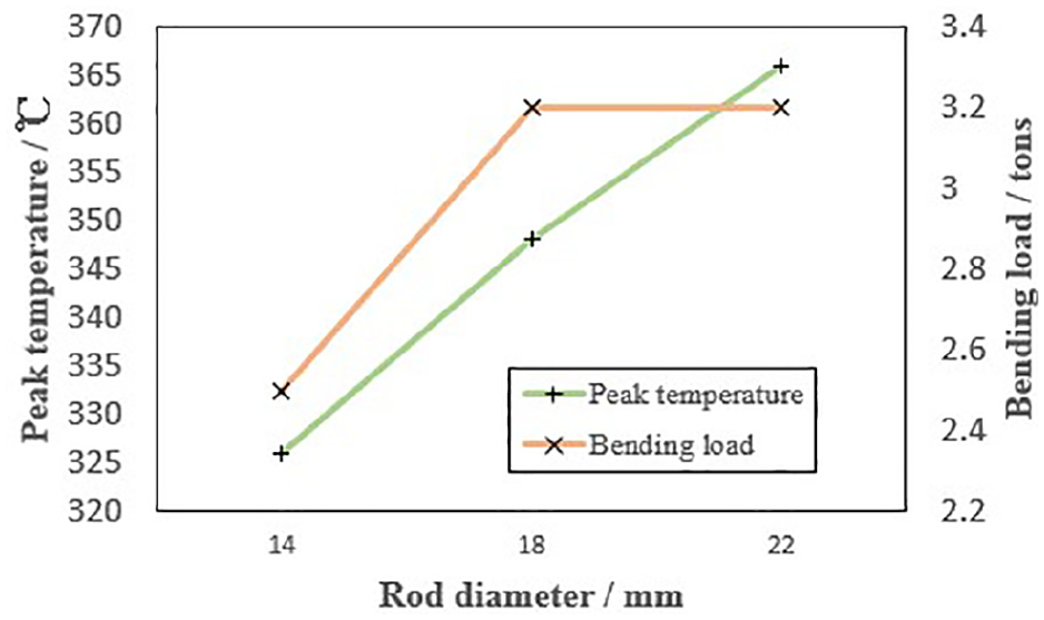
Peak temperature and bending load of the samples (Material: AA6063).
Offset
For the demand of large-area AM, it is necessary to carry out multi-pass friction surfacing. 84 Batchelor et al. 65 proposed that multi-layer additive exhibits fewer problems than single-layer additive. For single-layer additive samples, poor bonding defects are found at the edges, so the second layer should cover the edges of the first layer to repair the defects. 78 Tokisue et al. 73 made the friction surfacing additive of the second layer through a certain amount of offset on the basis of a single layer. The second layer of additive samples tends to tilt toward the first layer. The tensile strength of the multilayer specimens did not change much, but the elongation increased first then decreased as the offset increased. Shifting a smaller distance to the retreating side or a larger distance to the advancing side can increase deposition efficiency. Dilip et al. 91 carried out multi-layer friction surfacing AM of mild steel. The track overlay mode is shown in Figure 27. The first layer consists of five tracks, the second layer consists of four tracks, the third layer consists of three tracks. The experiment was performed at a fixed rotation speed of 1700 rpm, a traverse speed of 1.2 mm/s, and an axial pressure of 28 MPa. After processing one track each time, the 5 mm specimens on the edge are processed on the retreating side to eliminate defects at the edge. The transverse tensile properties of these deposits were found to be at par with standard wrought processed mild steel.

Picture of a multi-track multi-layer friction surfaced deposit.
Microstructure
Three layers of additive samples were made by Gandra et al. 92 using AA2024-T3 plates and AA6082-T6 aluminum alloy as the substrate and the consumable rod, respectively. It can be seen from Figure 28 that the material at interface between each combination in the middle part was fully bonded together, and defects were observed at the edges of both sides. A more uniform fine grain structure was observed in Figure 28(a). Figure 28(b) located at the bonding interface between the deposited layer and the substrate. The deposited layer did not diffuse into the substrate. The reason for the defects on both sides lies in the influence of the flash edge and axial load of consumables. The axial load in the middle part of consumables was greater than the circumferential regions. The rod rotation direction in the advancing side was the same as the traverse direction, but different in the retreating side. Therefore, the fluidity of the material on the advancing side was greater than that on the traverse side, and more defects appear on the edge of the retreating side.92,93 The grain size of the advancing side, center area, and retreating side of different layers was tabulated in Table 3. The variation of grain size in each layer was not much, indicating that the friction surfacing AM was able to produce a relatively uniform grain structure. 92

Cross section macrograph of multi-layer coating: (a) coating microstructure and (b) bonding interface to the substrate (Material: mild steel). 92
Grain size table for different positions. 92

Pirhayati and Aval 93 performed friction surfacing of 20 mm diameter AA2024 rod on 2 mm thick AA2024 aluminum alloy sheet. It was observed from Figure 29 that the grains in the center area were the finest and densest, followed by the advancing side and the retreating side, but the difference was not significant. Studies proved that the continuous and discontinuous recrystallization process led to significant grain refinement of the friction surfacing AM samples. Friction surfacing of alloy 718 rods were carried out by Dilip and Ram. 82 The deposit material was analyzed by EBSD. Grain in the deposit were significantly refined with high-angle grain boundaries. Due to the high strain rate and high temperature, the material was prone to discontinuous dynamic recrystallization. When the critical deformation condition is reached, the new grains originated at the prior grain boundaries began to grow. With the increase of dislocation density, the grain growth stopped and more new grains formed nucleation at the boundary.

Grain boundaries at different locations: (a) retreating side, (b) center zone, and (c) advancing side (Material: AA2024). 93
Mechanical properties
Hardness
Silva et al. 87 investigated the hardness distribution for the AISI 4340 steel deposit on a 5.6 mm ASTM A36 steel substrate as presented in Figure 30. In the horizontal direction, the hardness in the middle was slightly greater than that on both sides because of the ultrafine grains in the middle and the more bonding defects closer to the edge. 87 In the vertical direction, the hardness of the reinforced sample varied greatly with the process parameters. The hardness values observed were consistent with martensite formation upon cooling after deposition. At low rotation speed and traverse speed (_CC group), the hardness was in the range of 610 ± 60 HV. Similar trend was found by Shinoda et al. 80 for deposited AISI 440C martensitic stainless steel on low carbon structural steel SM490A.

Hardness distribution diagram: (a) vertical direction and (b) horizontal direction (Material: AISI 4340). 87
Tensile properties
Single-layer additive and multi-layer additive exhibit different tensile properties under different process parameters. Tokisue et al. 73 added BE-T4 aluminum alloy on a 5 mm thick 5052 P-34 aluminum alloy plate. Effect of friction surfacing conditions on deposition efficiency of monolayer deposit and effect of offset of second coating rod on deposition efficiency of multilayer deposit are shown in Figure 31. It is found that the tensile strength increases with the increase of the friction pressure, and decreases with the increase of the feed rate. The highest tensile strength is 267 MPa at 40 MPa friction pressure. The elongation also increases with the increase of friction pressure, and decreases with the increase of feed speed. Rotation speed has little effect on tensile strength and elongation. By comparing the tensile properties of multi-layer additive samples, it was found that the elongation increased regardless of the offset on either side. Although there is no major change in the tensile strength, compared with the single layer, the tensile strength has a great increase, around 319 MPa.

Effect on tensile strength and elongation: (a) friction pressure, (b) feed speed, (c) rotation speed, and (d) offset of second coating rod (Material: BE-T4).
Kumar et al. 83 used 15 mm diameter AA6063 consumable rods and 10 mm thick low carbon steel IS2062 plates for friction surfacing additive experiments. The best parameters of the process were studied. The factors studied include axial force, rotation speed, and traverse speed. The axial force was 4 kN (A1), 6 kN (A2), the rotation speed is 800 rpm (B1), 1000 (B3), and the traverse speed was 600 mm/min (C1), 800 mm/min (C2). The Figure 32 shows the tensile results of the experiment under different parameter groups. The experimental group used the following parameters: (1) A1B1C1, (2) A2B1C1, (3) A1B2C1, (4) A2B2C1, (5) A1B1C2, (6) A2B1C2, (7) A1B2C2, (8) A2B2C2. Three factors have positive effects on tensile properties. It yielded better performance under the conditions of low axial force, low traverse speed, high rotation speed and high axial force, high traverse speed and low rotation speed.

Tensile strength: (a) for different combinations and (b) effect of spindle speed (Material: AA6063).
Metal powder assisted additive manufacturing
Principle
The principle of metal powder assisted AM is to add metal powder in the process of additive processes. The mixing of metal powder can increase hardness and improve thermal stability, 94 inhibit the formation of metal oxides. 95 Different from the simple surface coating technology, the metal powder assisted AM technology mixes the metal powder into the material. The metal particles are tightly combined with the material to achieve better performance. While cold spraying, 96 laser melting, 97 thermal spraying, 98 and other surface additive technologies only modify the surface of the substrate, defects such as poor bonding performance, pores, and cracks may exist. Metal powder assisted AM uses friction stir processing or friction surfacing in the subsequent process to make up for these defects.99,100 There are many ways to add metal powder in the additive process. Some scholars have changed the friction stirring tool to act as a carrier of metal powder. Figure 33 shows one typical powder embedding methods.
Methods of metal powder embedding: powder mechanically inserted into the tool. 93
Process parameters
The method of adding powder includes embedding to the substrate or the rod, cold spraying and hot spraying. The metal powder processing methods are friction stir processing and friction surfacing. Table 4 summarizes the parameters of metal powder, including the size of metal particles, layers, rotation speed, traverse speed, shape and size of stirring tool, and processing method.
A summary of metal powder assisted additive manufacturing.
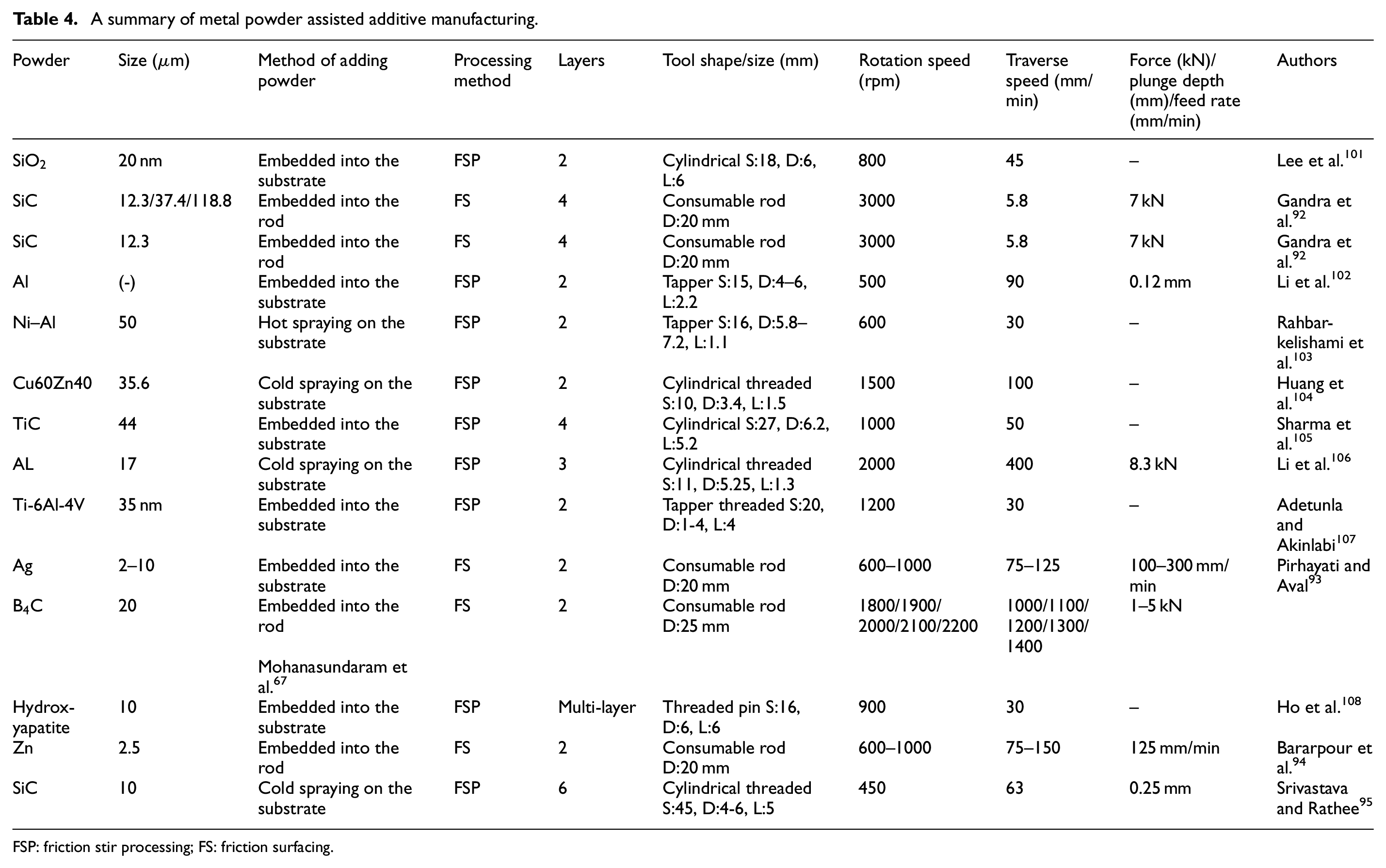
FSP: friction stir processing; FS: friction surfacing.
Powder size
The smaller the size of the metal powder, the easier to bond with the substrate. The smaller size is evenly distributed inside the material during processing, thereby achieving tight bonding. In powder spraying process, larger particles cause the particles to collide with the substrate and bounce off, which reduces the deposition rate and leads to waste of materials. Gandra et al. 92 drilled holes at the bottom of AA6081-T6 aluminum rods, and mechanically embedded the silicon carbide (SiC) of different sizes for friction surfacing. It can be clearly seen from Figure 34 that smaller particles were more effectively dispersed, while larger particle (118.8 μm) were not evenly distributed, increasing the surface roughness.

Microstructure of the inner and binding areas of the coating: (a) SiC 118.8 μm and (b) SiC 37.4 μm (Material: AA6082-T6). 92
Content (mass fraction)
In the metal powder assisted AM, it is necessary to control the amount of metal powder embedded into holes or grooves on the substrate surface, and then perform friction stir processing to uniformly disperse the powder.105,109,110 The modification of the stirring tool can be roughly divided into two types: one is to directly add metal powder when casting the stirring tool.67,111 Another method is to drill multi-directional holes at the bottom of the stirring tool and then fill metal powder into the hole. The number and location of embeddable holes can be different. When the stirring tool rotates, the area swept by the hole is different, so the mass fraction of the metal powder changes accordingly. Pirhayati and Aval 93 used the latter method to carry out the experiment and found that when the mass fraction of silver powder increased, the strength and hardness of the sample also increased, As shown in the Figure 35, after proper artificial aging heat treatment, the hardness and shear strength increase significantly. It was also found that the deposition efficiency is reduced because the frictional behavior between the silver powder and the substrate is different from that between aluminum rod and the substrate.

Hardness and shear strength of samples with different Ag content. 93
Microstructure
Mondal et al. 100 machined a groove with a depth of 0.5 mm and a width of 10 mm on the 1060 aluminum alloy plate. 7075 aluminum alloy powder (size: 30–45 μm) was added into the hole using selective laser melting technology. Then friction stir processing was performed, the traverse speed used was 50 mm/min, the tilt angle was 2°, and the tool rotation speed was 800 rpm. The macroscopic view of the interface after selective laser welding was presented in Figure 36. It can be observed that although there is a good bond between the metal powder and the substrate, there are a lot of pores. The existence of pores has a great influence on the mechanical properties. The interface after friction stir processing is shown in Figure 37. The disappearance of pores and the “onion rings” in the stirred zone can be clearly observed. The microstructure of bright and dark areas was examined by scanning electron microscopy. It was found that the particles in the dark areas were finer, and the bright areas had coarser precipitation. The experiment proved that sound microstructure can be obtained through metal powder assisted AM, and the metal powder can be fully mixed into the material.
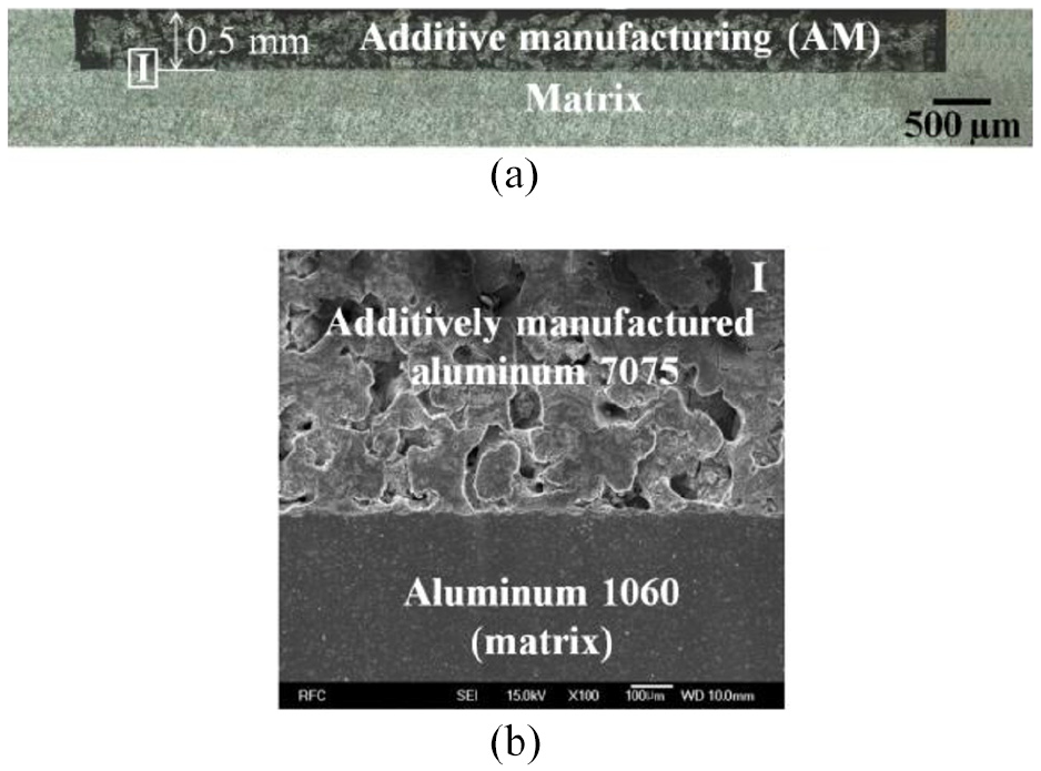
(a) Cross section of AMed aluminum matrix and (b) magnified view of the interface (region I). 100
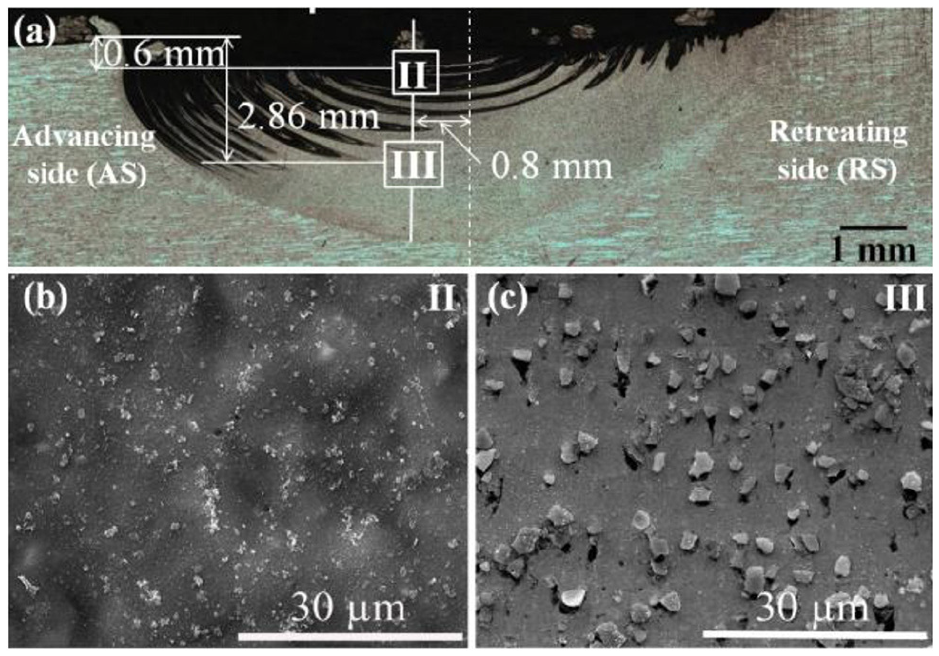
(a) Cross section of the AM-FSP specimen and SEM images of the regions, (b) II, and (c) III. 100
FSP can play the role of homogenizing particles. Adetunla and Akinlabi 107 studied the effect of multi-pass FSP processing on the 7075 aluminum substrate with Ti-6Al-4V as additive particles (average diameter 35 nm). The FSP tool was made of H13 tool steel, the tool shoulder diameter was 20 mm. The shape of the pin was tapper with threaded. With the increase of the number of FSP processing passes, the particle distribution becomes more uniform and finer. The clustered particles of Ti-6Al-4V were observed in the first two processing, and they were unevenly distributed in the matrix. No microstructure defects were observed after the third processing.
Bararpour et al.
112
drilled holes into the bottom of AA5083 consumables in friction surfacing to embed zinc powder (2.5 μm). The diameter of the bottom hole is 2.5 mm and the depth is 30 mm. The sample was observed by XRD, and the presence of zinc-containing compounds was found. Pirhayati and Aval
113
put Ag powder (1–2 μm) in the artificial hole at the bottom of the AA2024 aluminum rod. Friction surfacing was carried out on the substrate of the same material. The SEM image of the samples with and without powder is shown in Figure 38. It was found that more precipitated phases appeared in the silver-containing samples. The composition of the precipitation phase was further analyzed by EDS technology and the compounds such as
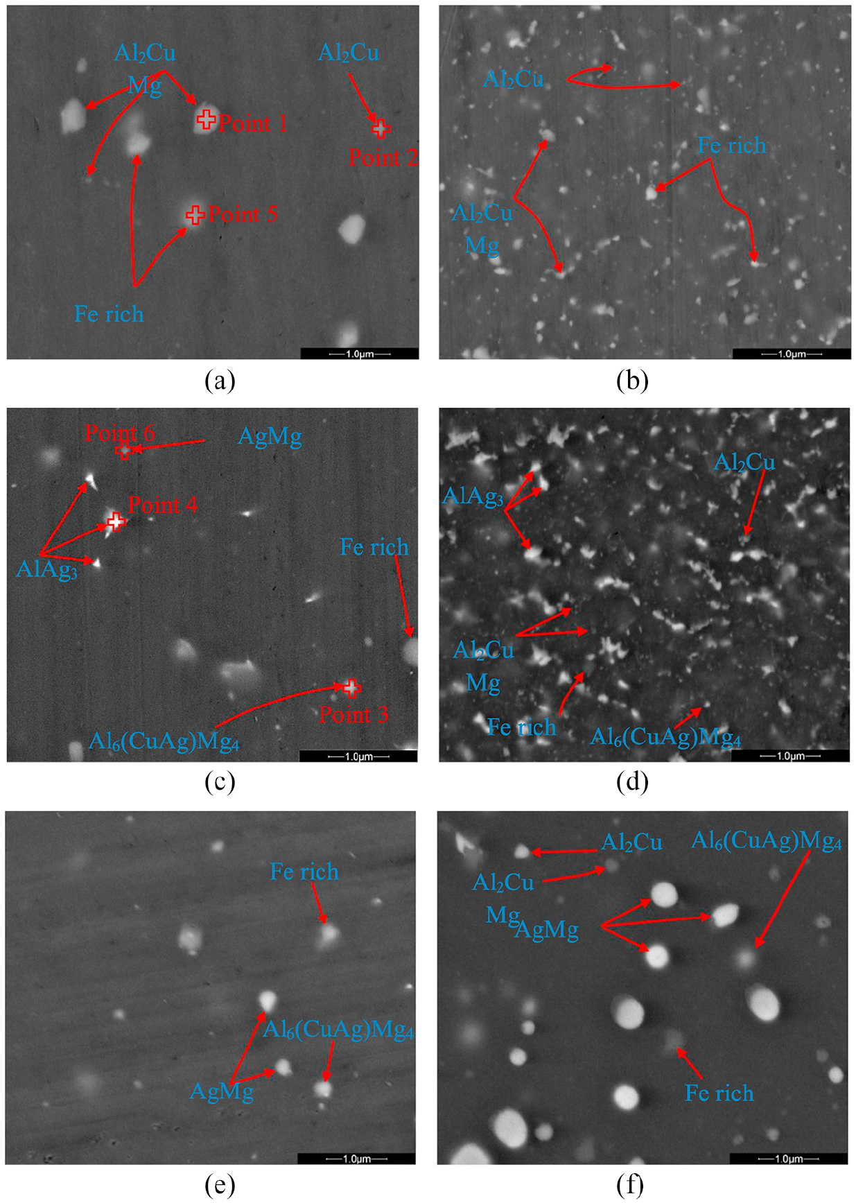
The SEM image of coated sample: (a) the samples without silver and (b) the sample containing silver (Material: AA6082-T6). 113
Mechanical properties
Hardness
Lee et al.
101
added SiO2 powder into the grooves on AZ61 base metal, and then performed the FSP process. The hardness distribution of the central cross-sectional area of the processed sample was shown in Figure 39. Among them, “D” represents the number of grooves in the base material, and “P” represents the number of friction stir treatments. The Gray area represents the location of grooves where
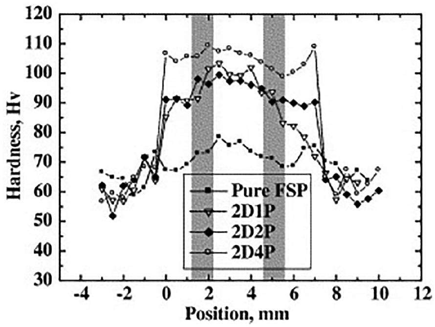
Typical variation of the microhardness (Material: AZ61Mg). 101
With the increase of the height of the added material, the reheating effect of continuous processing coarsens the grains. Gandra et al. 92 used AA6082-T6 consumable rod with embedded SiC particles to perform friction surfacing AM on AA2024-T3 substrates. The hardness distribution was presented as shown in Figure 40. In the substrate the hardness increased toward the bonding interface. This was due to the plastic deformation caused by the scrubbing of the consumable rod. However, in the additive region, the hardness generally decreased toward the interface. Under continuous reheating, the grains of the underlying additive material become coarser.

Hardness distribution in vertical direction of multilayer friction surfacing additive manufacturing. 92
Khodabakhshi et al. 114 cold sprayed AA7075 powder on the AZ31B magnesium alloy plate, and then performed FSP process. Figure 41 shows the indentation load-displacement graphs before and after FSP. A higher indentation depth under a constant load means a lower hardness. It was found that the hardness of the substrate after FSP was decreased owing to the grain coarsening and annealing of dislocations. The hardness of the cold sprayed layer was increased after FSP under the shoulder due to the grain refinement. Cold spray technology also had a strengthening effect on hardness, but the performance of samples combined with FSP was better.

Indentation load-displacement graphs and the related hardness values for the AZ31B alloy and cold sprayed AZ31B-AA7075 structure before and after FSP (Material: AZ31B magnesium alloy). 114
The hardness of the processed samples under different parameters also showed different performance. Xie et al. 115 conducted laser cladding experiments on the surface of 45 steel, and the powder used was Ni-Cr-Fe alloy powder. FSP treatment was carried out after laser cladding experiment. A cylindrical tool made of a columnar WC–Co hard metal without a stirring pin was adopted. The hardness curves of the cross section of the sample at different rotation speeds were shown in Figure 42. Overall, the hardness of the laser cladding layer has increased from 300 HV to over 400 HV. As the rotation speed increased, the hardness also increased. This was attributed to the reason that a greater plastic deformation at high speeds resulted in a more refined structure.

Microhardness in depth of the cross section of the Co–Cr–Fe alloy prepared by laser cladding and FSP (Material: 45 steel). 115
Tensile strength
Dixit et al. 116 filled a powder mixer of 40 atomic% of graphite with balance amount of aluminum in the grooves of pure aluminum plate (99.9% purity). Figure 43 shows the tensile stress-strain curve of the material. The ultimate tensile stress of the composite material was 147.5 MPa, much greater than those of pure aluminum. In contrast, the elongation of the composite material was 26%, smaller than that of FSP aluminum. Bararpour et al. 94 carried out metal powder assisted AM experiments by punching holes in the bottom of Al-Mg consumable rods and embedding zinc powder (2.5 μm). The strength-normalized displacement curves of the sample were shown in Figure 44. It can be seen that the addition of zinc powder improved the performance greatly. The effect of aging on the properties was compared. The best strength 213.83 MPa occurred at 8 h. During the 4 h aging process, the crystal grains grew and non-homogeneous precipitates caused performance degradation. For 8 h aging, intermetallic compounds containing zinc were precipitated to improve the strength. When the heat treatment continued, the zinc compounds decreased.

Mechanical deformation behavior of the pure Al, FSP processed Al and the processed composite plates (Material: AL). 116

The strength-normalized displacement curve of Zn containing and Zn free samples (Material: AA5052). 94
The tensile results of multi-layer AM with titanium powder (63 μm) embedded in the bottom of 20 mm AA5083-H112 consumable rods were presented by Karthik et al. 117 in Figure 45. Compared with consumable rods, the tensile strength of the single-layer composite samples was slightly higher. The tensile property of the multi-layer composite sample was worse than that of the single layer sample. The presence of oxides and incomplete bonding on the multi-pass processed interfaces resulted in weak tensile properties.

Typical tensile stress–strain plots (Material: AA5083). 117
Discussion
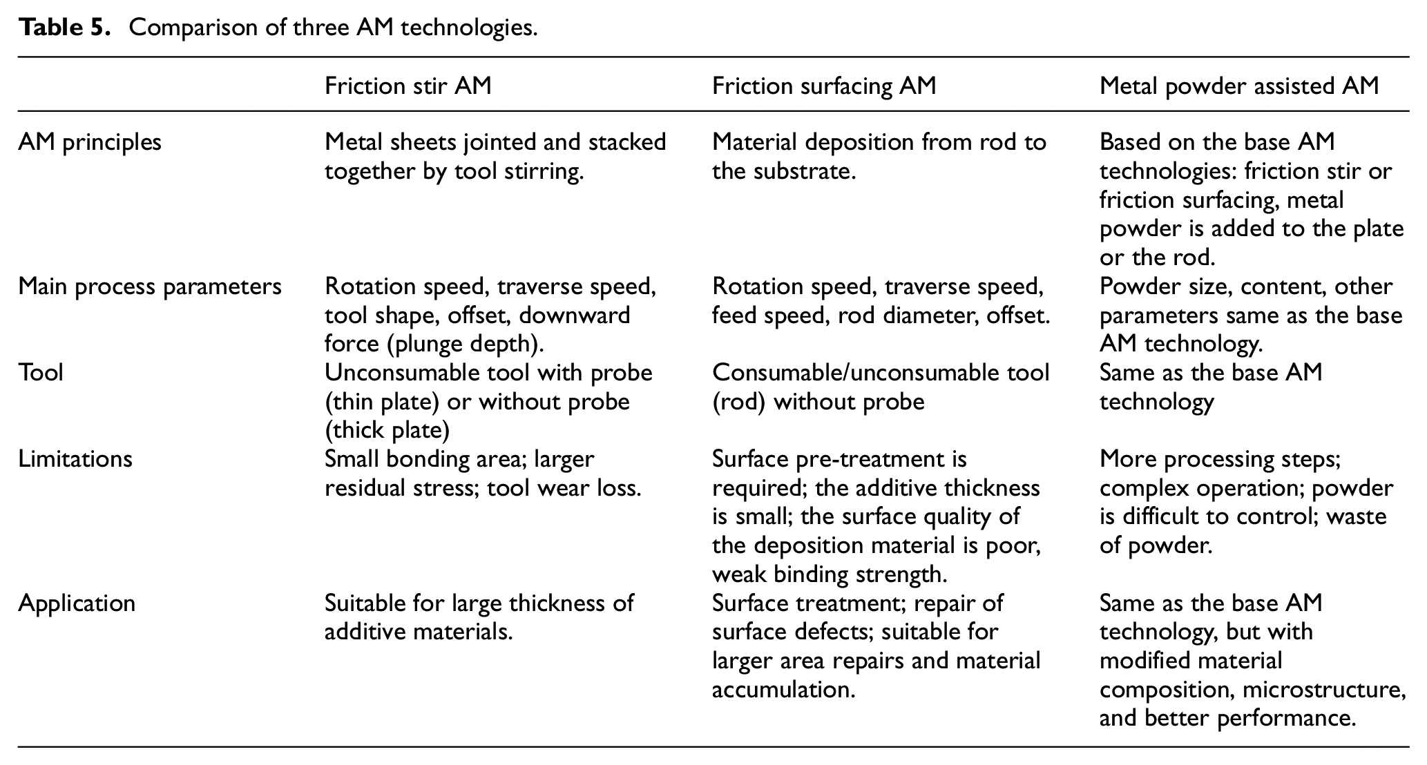
FAM technology has been applied to the manufacture of 28% of engineering products, and it is expected that it will be applied to the manufacture of 52% of engineering products in 2030. Europe and the United States already have a complete AM production chain. 118 Friction stir AM is the most widely used while the friction surfacing AM technology is mainly used for surface repair and modification. Metal powder assisted AM technology is mainly used to manufacture smaller parts, molds, tooling equipment, etc. The comparison of three AM technologies is presented in Table 5.
Comparison of three AM technologies.
For friction stir AM of metallic materials, the hooking defect at the specimen edge is the main factor affecting the performance. In response to these problems, reasonable control parameters and multi-pass processing can effectively avoid hooking defects. Multi-pass processing includes multiple processing in one direction and multiple processing back and forth. With the increase of processing passes, the number and size of precipitates decrease, the grain size becomes finer, and the tensile properties gradually increase.40,119 Faced with grain coarsening under the influence of heat, the solution is to accelerate cooling as much as possible. Li and Shinoda 120 used a water spray system to cool friction surfacing welding. As a result, the deposition efficiency of consumables increased from 19% to 31%, the strength and position of the water spray system also changed the geometry of the sample. Repeated re-stirring and re-heating lead to uneven distribution of grain size and the precipitated particles, which cause residual stress and micro-cracks. The hazards of residual stress include the reduction of ultimate tensile stress and fatigue life. However there has been very little research work on the effect of residual stress and its effect. For residual stress in FAM, the most effective method is controlling process parameters. Appropriate parameters can control compressive stress and thermal effects. In addition, a shot peening technique was proposed in the literature of Ziemian et al. 121 Other methods to reduce residual stress include overheating aging, ultrasonic impact strengthening, vibration aging, etc.122–124 The tool works in a harsh environment with high temperature and high stress. Therefore, the tool wear has been problematic, significantly shortening the tool life. Sadhu et al. 125 compared the wear of stirring tool: (a) as-received (AR), (b) heat treated (HT), (c) laser remelted (LR), (d) S6 hard-faced by direct metal laser deposition (S6 tool). In Figure 46, it can be observed that the S6 hard-faced tool (S6) has the least wear.

Tool pin morphology after 125 mm long FSP pass: (a) as-received (AR), (b) heat treated (HT), (c) laser remelted (LR), and (d) S6 hard faced by direct metal laser deposition (S6 tool). 125
For the friction surfacing AM, after the first layer of additive sample is successfully deposited, the second layer produces a large shear stress, it is necessary to ensure that there is sufficient bond strength between the first layer sample and the substrate so that it will not fall off. It is desirable to control the process parameters and ensure that each layer is carried out under the optimal process parameters. One of the drawbacks of the friction surfacing AM is that the additive material cannot achieve the complex shape and required precision. Necessary subtractive manufacturing can be carried out, including turning, grinding, and other processing. 38 This will lead to a waste of materials. There is no mature technology to improve its accuracy, which requires further research in this field. If the parameters are improper, flash will be formed on the substrate, which is also a waste of material. The deposited material edges on both sides are not bonded to the substrate, which has a great influence on the tensile strength and bending properties. The method of secondary surfacing with an offset can compensate for this defect, and increase the surfacing area. During processing, oxides and impurities are easily generated at the bottom of consumables rods. If it is processed directly without treatment, it is easy to mix impurities into the sample. The precipitates formed by these impurities and oxides at the processing interface are often defective parts of fracture extension. Usually, acetone is used to clean the bottom of consumables and degrease the surface, 65 which can effectively reduce the amount of precipitates in the microstructure. Acetone is a safe dissolving agent that can dissolve substances and will not cause adverse effects on the human body and the environment. There are also many methods for surface degreasing, including organic solvent degreasing, chemical degreasing, electrolytic degreasing, etc., which can effectively remove oil, dust, and iron filings.
Conclusion
In this paper, the state-of-the-art of friction additive manufacturing technologies: friction stir AM, friction surfacing AM, and metal powder assisted AM was reviewed and studied. From the above discussion, the following conclusions can be drawn:
Based on the nature of solid-state processing, the FAM can improve the mechanical performance of the additive materials comparing with traditional powder bed fusion AM technologies. The application exhibits great potential and will expand rapidly in the coming years.
Friction stir AM can obtain a complete bonding interface between each layer. The grain is refined during the process. Increase in rotation speed can increase material fluidity, but too high speed will cause more defects. High traverse speed can lead to incomplete softening, while low speed makes the material excessively plasticized. Kissing bond defects are common in the middle bonding area, and hooking defects are present at the edges. In terms of the stirring tool design, the key is to make the material produce better fluidity.
Friction surfacing AM can produce uniform and fine grain structure. Incomplete bonding may exist at the edge of the additive materials. The higher the rotation speed, the smaller the width and thickness of the deposition. The slower the traverse speed, the greater the thickness of the deposition. The increase in axial force improves the strength, but reduces the thickness and increases the width. Appropriate offset can compensate for the edge defects of single-layer samples and increase the area of additive materials.
For metal powder assisted AM, there are many variants, depending on the powder addition and processing methods. There is relatively little research on each variant. Addition of powder to either the consumable rod or the substrate will inevitably increase the process time. To obtain a sound microstructure, more process parameters need to be controlled compared with friction stir AM and friction surfacing AM.
For the mechanical performance of the additive material, current studies mainly focus on the hardness and tensile properties. However, the research on the performance under cyclic loading is very rare. The fatigue damage process and failure properties should be investigated in the future study.
Footnotes
Handling Editor: James Baldwin
Declaration of conflicting interests
The author(s) declared no potential conflicts of interest with respect to the research, authorship, and/or publication of this article.
Funding
The author(s) disclosed receipt of the following financial support for the research, authorship, and/or publication of this article: This work is supported by Zhejiang Province Public Welfare Technology Application Research Project (Grant No. LGJ21E050001).