
Abstract
This paper studied the dynamic process of a dual-trolley overhead crane transshipping rigid-body cargo with degrees of spatial freedom. By taking the tensile stiffness of wire rope, the bending stiffness of box girder and the mass of cargo as variables, six different working conditions were calculated. The influences of the variables on spatial movement of slender cargo were analyzed. To verify the presented analytic model, a virtual prototype model was constructed by using the commercial software ADAMS and ANSYS. The consistency of the calculation results from the two different models proves the effectiveness of the analytic model presented in this paper.
Keywords
Introduction
In the past decades, the transportation capability and lightweight design of overhead crane has raising more and more concerns. In practice, as the cargo grows larger and heavier, it often needs to be cooperatively delivered by two trolleys. As special equipment for transferring the heavy and slender cargo, the dual-trolley overhead crane develops rapidly in the field of mechanical engineering. The specific transshipping process has been illustrated in detail in Figure 1 of Yao et al. 1 In the figure, the cargo needs to be horizontally upraised and steadily transshipped to the prearranged location by the cooperated control of the dual-trolley and girder. According to Masoud’s 2 research, heavy payload combined with the dynamic stretch of the hoist cable had a significant impact on the configuration of the hoisting mechanism and the pattern of oscillation. The elasticity of wire rope and crane structure may introduce considerable change in the oscillation frequency of the cargo, which resulted in a significant impact on the performance of the anti-sway control system. Therefore, in order to improve the safety, reliability, and economy of the transshipping process, the dynamic research and elastic influence on the lightweight crane becomes crucial.

The transshipping motion of dual-trolley overhead crane.
There have been lots of researches highlighting the transshipping dynamics for different kinds of cranes. Lu et al. 3 presented a precise model of dual overhead crane system by utilizing the Lagrangian modeling method. Zhao and Huang 4 develops a new method to predict the natural frequency of dual planar cranes with different cable lengths. Ku and Ha 5 carried out the dynamic response of the multi-cranes in block lifting operation to increase the lifting capacity for ship and offshore structure building. Huang et al. 6 pointed out that large payloads and the actual configuration of the hoisting mechanism may transform the crane to a double-pendulum system with a distributed-mass payload. Although the aforementioned literatures have studied the dynamics of different kinds of cranes, the elasticity of crane system is out of consideration. The ignoring of structural elasticity, as stated in Masoud, 2 may introduce considerable differences for the dynamic analysis and anti-swing control of crane system.
Masoud 2 developed an analytic approximation of the oscillation frequency of the hoisting mechanism of a quayside container crane, in which the elasticity of the hoisting cables were taken into consideration. Fatehi et al.7–9 has dealt with the modeling and control problems of an overhead crane with a flexible cable. A dynamical model including both transverse vibrations of the flexible cable and large swing angles of cable was developed. Zhang and Abba 10 presented a dynamic model of the trolley-payload pendulum system considering both the flexibility and the damping of the hoist rope. Simulation results show that the flexibility of the hoist rope cannot be ignored especially near the destination of the final position of the payload. Similarly, Moustafa et al. 11 considered the dynamic modeling problem of the overhead crane with flexible cable. The transverse vibrations of the flexible cable and trolley motion were included in the analysis. In Tuan’s research,12–14 the flexibility of wire rope was characterized by a spring-damper. Hu and Liu 15 modeled the whole deployment system of offshore structure including the wire rope as a lumped mass model, and the discretization scheme for the cable was presented. d’Andréa-Novel and Coron 16 studied the uniform exponential stabilization of an overhead crane with flexible cable. Rong et al. 17 developed a multibody model of the overhead crane system by regarding the wire rope as a series of rigid segments connected by hinges. In the above literatures, only the elasticity of wire rope was taken into account in the modeling of crane-payload system. The modeling processes for wire rope are various. For instance, the wire rope was considered as elastic body with continuously distributed mass in Refs.7–11 However, it was characterized by spring and damper in Refs.12–15 In addition, it was modeled as a series of rigid segments connected by hinges in Rong et al. 17
In recent years, there have been lots of literatures concerning on the structural elasticity of crane. Trąbka 18 summarized ten variants of a computational model for a telescopic boom crane that differs in number and selection of flexible components. To obtain transverse and longitudinal vibrations of a gantry crane system subjected to an elastically suspended moving body, Zrnić et al. 19 presented a combined finite element and analytical method. Jerman et al. 20 formulated a non-linear mathematical model of the load sway during the slewing motion, in which the structure’s elasticity and damping were taken into account. Kimmerle et al. 21 presented a model of an elastic crane transporting a load by means of controlling the crane trolley motion and the crane rotation, in which the extension arm of the crane was considered as a homogeneous beam. Cao et al. 22 constructed a mathematical model of a tower crane with long flexible boom. Both the vertical deformation and the horizontal deformation of the boom, modeled as an Euler-Bernoulli boom, were considered in the model. Rauscher and Sawodny 23 presented a modeling approach for the slewing control based on a distributed-mass model, in which the crane jib was also modeled as an Euler-Bernoulli beam. Golovin and Palis 24 pointed out that one of the most significant structural dynamics problems of large gantry cranes are elastic vibrations in trolley travel direction. Ren et al. 25 studied the dynamic response of moored crane-ship. The boom was modeled based on finite element method, while the payload was modeled as a planar pendulum of point mass. In Trąbka’s research, 26 the influences of flexibilities of seven crane structural components on working accuracy in relation to the trajectory of the load were estimated. In addition, the elasticity of structural component was also taken into account in Refs.27–34 to obtain the precise response of crane system. In the above literatures, although the elasticity of crane structure is concerned, the wire rope is modeled as rigid rod. Unfortunately, the elastic coupling effects between the structural component and the wire rope are not included in the studies.
So far, some literatures have begun to study the coupling effects between the structural component and the wire rope in crane system. He et al. 35 proposed a model of dynamics analysis of an offshore crane based on virtual prototyping technique. The tower column and the wire rope were simultaneously modeled as flexible bodies in the model. Adamiec-Wójcik et al. 36 presented an offshore knuckle boom crane model, in which the flexibility of booms and the rope system were taken into account. The rigid finite element method was used for the discretization of flexibility boom and the wire rope was equivalent as spring-damper model.
Unlike the previous studies, this paper mainly focuses on the influences of structural elasticity on the dynamic response of dual-trolley overhead crane carrying rigid-body cargo. The elasticity of crane girder and wire rope was simultaneously taken into account in the model as well as the elastic coupling effect between them. Moreover, the cargo was assumed as a rigid body rather than a concentrated mass. Section 2 introduced the composition and motion of the crane system. The position and velocity vectors of the key points in the crane system were represented in Section 3, then the governing equations of crane system was deduced by the Lagrange’s Equation. In Section 4, six different numerical examples were calculated. The influences of variation of box girder bending stiffness, wire rope tensile stiffness, and payload mass on the motion of cargo were analyzed. A virtual prototype model was created in Section 5 and the validity of the analytical model was partially verified. Section 6 summarized the conclusions obtained by the aforementioned calculations.
Descriptions of dual-trolley crane system
The process of the dual-trolley overhead crane transshipping the distributed-mass cargo is illustrated in Figure 1. In the initial moment, an inertial coordinate system, Oxyz, is established on left-end point of the box girder. The box girder possesses with big-span, slight-weight, and minor-rigidity. Thus, it is considered as an Euler-Bernoulli beam with uniform cross section and density. In the transshipping motion, the girder travels along the forward direction of y-axis and the trolleys traverse along forward direction of x-axis. The left and right trolleys are denoted as c1 and c2, respectively, and are deemed as point masses. The slender cargo, suspended by wire ropes at the two suspension points, p1 and p2, is considered as a rigid body possessing with spatial freedom. A conjoined coordinate system O′x′y′z′ is added to the mass center of the rigid body to analyze the motion and attitude of the body. A set of Euler angles φ, θ, and ψ, defined as rotating around the x′-axis, y′-axis, and z′-axis of the conjoined coordinate system, respectively, are used to describe the attitude of the rigid body. The elastic attribute of the wire rope is taken into account and thus, a distributed parameter model is adopted to represent the kinetic and the potential energy of wire rope. To aid the study, the swing angle, θ, of particle on cargo is orthogonally decomposed as θ x and θ y , in which θ x is the projection of the swing angle, θ, on oxz-plane and θ y is the angle projection on oyz-plane. For instance, the definitions of swing angle and its projections of cargo mass center, pc, are illustrated in Figure 2.

Definitions of swing angle, θ, and its projections, θ x and θ y , for mass center of cargo.
Governing equations
Position and velocity vectors
To facilitate the analysis of the problem, the three-dimensional transshipping motion is projected onto the Oxz- and Oxy-plane, respectively, as illustrated in Figures 3 and 4.

Projection of transshipping process on Oxz-plane.

Projection of transshipping process on Oxy-plane.
In the inertial coordinate system Oxyz, the position vector of an arbitrary particle on the girder can be expressed as

where
The position vector of trolley, ci (i = 1, 2), can be described as

where xci(t) is the x-axial coordinate of ci; v(xci,t) and w(xci,t) are the deformation projections of girder on Oxy- and Oxz-plane, respectively, at ci.
The position vector of suspension point, pi (i = 1, 2), on cargo can be exactly expressed as

where θ
xi
denotes the angular projection of θ
i
, defined as the swing angle of suspension point pi, on Oxz-plane; θ
yi
denotes the angular projection of θ
i
on Oyz-plane; lpi represents the initial length of wire rope li at equilibrium state, affected only by the cargo weight; ui(x,t) represents the axial extension of an arbitrary particle on the wire rope in the transshipping process;
Assuming the cargo is homogeneous and has a consistent shape, the position vector of its mass center,

Practically, in the transshipment process, the swing angle, θ, and its time derivative,


where the notation • denotes the derivative of functions with respect to time t. The differential operation of the compound function F(xci,t) (F = w, v and i = 1,2) should be expanded as

in that xci is also a time-varying function.
Kinetic energy of system
In the transshipping process, the total kinetic energy of the dual-trolley crane system consists of Tb, Tc, Tr, and Tp contributing from box girder, dual-trolley, wire rope, and cargo, respectively.
According to equation (5), the kinematic energy of girder, Tb, can be expressed as

where ρ, A, and lb denote the density, the sectional area, and the span of box girder.
According to equation (6), the kinematic energy of dual-trolley, Tc, can be expressed as

where mci (i = 1, 2) represents the mass of trolley ci.
The kinematic energy of wire rope, Tr, can be expressed in distributed parameter model form as

in which ρri and Ari represent the density and sectional area of wire rope lpi, respectively;
The kinematic energy of spatial cargo Tp consists of two parts, that is, the translational energy TpT and the rotational energy TpR. The specific expression of Tp can therefore be expressed as
In the above equation,

Due to the symmetry of the cargo structure and its lifting moment, the roll angle φ can be ignored. The pitch angle θ and the yaw angle ψ are not free variables. They are coupled with the beam and the wire rope and are constrained by the lifting points. Therefore, similar to the centroid coordinate vector of the cargo, they are also a function of the lifting point position. By neglecting the high order infinitesimal term, the explicit expressions of the two angles are

in which lp1p2 represents the distance between the two suspension points.
Potential energy of system
In the transshipping process, the total potential energy of the dual-trolley crane system consists of Ub, Uc, Up, and Ur contributing from box girder, dual-trolley, cargo, and wire rope, respectively.
Specifically, the deformational energy of girder, considered as an Euler-Bernoulli beam, can be expressed as
where Izz and Iyy denote the inertia moment of beam cross section with respect to z- and y-axis, respectively; the notation ″ denotes the second derivative with respect to spatial variable x.
The elastic potential energy of wire rope, Ur, consists of the generalized potential energy, caused by the static stretching force, and the elastic potential energy, caused by the dynamic axial stretch. The potential energy of wire rope can be expressed as

where Pi (i = 1, 2) denotes the stretching force of wire rope in the equilibrium state; EiAi (i = 1, 2) denotes the tensile stiffness of wire rope. The stretching force, Pi (i = 1, 2), can be expressed in detail as

in which mlpi (i = 1, 2) represents the mass of wire rope; g is the local gravity acceleration.
By taking the Oxy-plane as the zero potential energy plane, the gravitational potential energy of dual-trolley, Uc, can be described as

The gravitational potential energy of cargo, Up, can be described in detail as
where rpcz is the projection of position vector of cargo mass center on z-axis.
Governing equations
Before formula derivation of governing equations, it is expedient to introduce the following non-dimensional parameters:

and the dimensional ratios
By using the Rayleigh-Ritz method and the non-dimensional coordinate ξ, the elastic deformation of box girder can be assumed as

where

where γi and λi are the non-dimensional circular eigenfrequencies of the ith out-of-plane and in-plane mode.
Similarly, the elastic deformation of wire rope can be assumed as

in which

To get the governing equations, one can firstly decompose w(x,t) and v(x,t) via equation (19) and decompose ui(x,t) via equation (21). Secondly, one can take the column vector

in which
What needs to be added is that, according to the geometrical relationship of the two hanging points, p1 and p2, there is a constraint equation for the argument vector

By substituting equation (3) into the above equation and neglecting the nonlinear term of higher order infinitesimal, we have the following results

Obviously, the constraint equation is a function of the two variables θx1 and θx2. The governing equation of the dual-trolley crane system in transshipping process, therefore, is a set of differential-algebraic equations consisting of equations (23) and (24).
Analysis of effects of elasticity and mass
In the subsequent analysis, the influence of elasticity of wire rope and box girder, and the influence of payload mass of cargo on the transshipping process will be analyzed, respectively. To facilitate the comparison of results, the analysis cases and the relevant parameters are sorted and listed in Table 1. Without loss of generality, the lengths of the two wire ropes are assumed identical, that is, Lp1 = Lp2 = Lp; furthermore, the two wire ropes are assumed to have the same tensile stiffness, that is, E1A1 = E2A2 = EA. The cross section of box girder is assumed square, which result in the same bending stiffness in the oxy- and oxz-plane, that is, EIzz = EIyy. The parameters of crane system are listed in Table 2. The transverse velocity of trolley and the travel velocity of girder are assumed identical and portrayed in Figure 5. The initial values of the generalized coordinate vector,
Numerical cases and the corresponding parameters for analysis.

Parameters employed in crane system.


The traversal and travel velocity for trolley and girder.
Before the analysis, it should be noted that, due to the symmetry of the system and the consistency of the initial values, the results of the two out-of-plane swing angles, θy1 and θy2, are almost the same in all cases. Thus, in the subsequent studies, the results of the two angles are labeled as θy1 = θy2 = θ y . Similarly, the two in-plane swing angles, θx1 and θx2, also have the same result, so the two angles are labeled as θx1 = θx2 = θ x in the following sections.
Influence of wire rope elasticity
Calculation results for case 1
As illustrated in Figure 6, in case of the tensile stiffness of wire rope EA = 2.80 × 10⁴ N and EA = 2.80 × 10³ N, the trajectory projections of cargo mass center on x-y plane agree well with each other. The differences in amplitude and period of projection curve, however, become noticeable when EA = 2.80 × 10² N. This means along with the decrease of tensile stiffness of wire rope, the elastic deformation increases and finally, it can notably affect the motion of cargo when the tensile stiffness decreases to a minor value.

The trajectory projection of cargo mass center on x-y plane: () EA = 2.80 × 10⁴ N; ( ) EA = 2.80 × 10³ N; (··········) EA = 2.80 × 10² N.
The trajectory projections of cargo mass center on z-axis are exhibited in Figure 7. The amplitude of the trajectory projection, in case of EA = 2.80 × 10⁴ N, is limited between 3.50 and 3.62 m, while it is increased to 3.65 m when EA = 2.80 × 10³ N. Although the amplitude difference between the two curves is small, the period difference is conspicuous. The partial enlarged drawing of the trajectory projection is displayed in Figure 8, where one can see that the curve period in case of EA = 2.80 × 10⁴ N is smaller than that in case of EA = 2.80 × 10³ N. As time goes on, the difference gets bigger. At the time t = 10.5 s, the two curves become opposite in phase. Compared with the two aforesaid curves, the amplitude and phase differences of the projection curve in case of EA = 2.80 × 10² N are remarkable as illustrated in Figures 7 and 8. The amplitude is much bigger and the period is much longer due to the greater elongation of wire rope. The elongation of wire rope makes the length become bigger, which can change the amplitude and the period of swing angle of cargo. The bigger the rope length, the greater the amplitude and the period.
The trajectory projection of cargo mass center on z-axis: () EA = 2.80 × 10⁴ N; () EA = 2.80 × 10³ N; (··········) EA = 2.80 × 10² N.
The partial enlarged drawing of trajectory projection of cargo mass center on z-axis: () EA = 2.80 × 10⁴ N; () EA = 2.80 × 10³ N; (··········) EA = 2.80 × 10² N.
The in-plane swing angle θ x , as shown in Figure 9, matches well with each other in case of EA = 2.80 × 10⁴ N and EA = 2.80 × 10³ N. Similar to the simple pendulum motion, the two curves keep oscillating at approximately equal amplitude. However, the amplitude is no longer constant when the tensile stiffness EA = 2.80 × 10² N. The equal amplitude oscillation is modulated by a sine curve due to the tiny tensile stiffness of wire rope. In addition, the curve period on this occasion also changed significantly, especial in the later stage.
Effect of tensile stiffness on in-plane swing: () EA = 2.80 × 10⁴ N; () EA = 2.80 × 10³ N; (··········) EA = 2.80 × 10² N.
As shown in Figure 10, the out-of-plane swing angle θ
y
, in case of EA = 2.80 × 10⁴ N, has the motion characteristics of uniform-acceleration, uniform-velocity, and uniform-deceleration. The motion features, however, become inconspicuous when EA = 2.80 × 10³ N and EA = 2.80 × 10² N due to the decreasing of wire rope tensile stiffness. The difference in amplitude of curve is tiny in case of EA = 2.80 × 10⁴ N and EA = 2.80 × 10³ N, while the difference becomes obvious when EA = 2.80 × 10² N. As time goes on, the periodic differences are becoming more and more significant as illustrated in Figure 11. It also shows that the curve with less tensile stiffness of wire rope has a smaller period, which is in contrast to our common sense. This is mainly caused by the combined elastic effect of box girder and wire rope behaving as stiffness regulator in
Effect of tensile stiffness on out-of-plane swing: () EA = 2.80 × 10⁴ N; () EA = 2.80 × 10³ N; (··········) EA = 2.80 × 10² N.
The partial enlarged drawing of out-of-plane swing: () EA = 2.80 × 10⁴ N; () EA = 2.80 × 10³ N; (··········) EA = 2.80 × 10² N.
Figure 12 shows the motion trajectory of the cargo mass center along y-axis. It is noticeable that, due to the elastic effect of wire rope, the trajectory of cargo mass center oscillates around the inelastic motion curve. The slight vibration behaves as disturbance to the expectant motion, which may make the movement of cargo unstable, and might cause trouble for the motion control of cargo.
The motion trajectory and its partial enlarged drawing of cargo mass center along y-axis: () EA = 2.80 × 10⁴ N; ( ) EA = 2.80 × 10³ N; (··········) EA = 2.80 × 10² N; (
 ) the inelastic motion.
Calculation results for case 2
As illustrated in Figure 13, the trajectory projections of cargo mass center on x-y plane have the same pattern with those in Figure 6. The difference is that the amplitude of curve in Figure 13 is slightly smaller.
The trajectory projection of cargo mass center on x-y plane: () EA = 2.80 × 10⁴ N; () EA = 2.80 × 10³ N; (··········) EA = 2.80 × 10² N.
By comparing Figure 14 with Figure 7, the same research conclusion can be obtained. Under the condition that the wire rope has the same tensile stiffness, the amplitude of the curve in Figure 15 is smaller than that in Figure 8. This is because in Case 2 the position of the trolley on the girder is constantly changing, rather than being in the mid-span of girder as in Case 1.
The trajectory projection of cargo mass center on z-axis: () EA = 2.80 × 10⁴ N; () EA = 2.80 × 10³ N; (··········) EA = 2.80 × 10² N.
The partial enlarged drawing of trajectory projection of cargo mass center on z-axis: () EA = 2.80 × 10⁴ N; () EA = 2.80 × 10³ N; (··········) EA = 2.80 × 10² N.
Similar to the motion of an inelastic crane-wire rope-cargo system, the in-plane swing angle θ x , in case of EA = 2.80 × 10⁴ N and EA = 2.80 × 10³ N, has the motion characteristics of uniform-acceleration, uniform-velocity, and uniform-deceleration as shown in Figure 16. The two curves fit perfectly, which means that the elasticity of wire rope at this level has little effect on the in-plane swing of cargo during the transverse motion of dual-trolley. As the tensile stiffness continues to decrease, for example to EA = 2.80 × 10² N, its influence on the in-plane swing angle begins to appear as illustrated in Figure 17. Under this condition, the tensile stiffness affects not only the amplitude but also the period of the in-plane swing angle. The same conclusion can also be obtained from Figure 18.
Effect of tensile stiffness on in-plane swing: () EA = 2.80 × 10⁴ N; () EA = 2.80 × 10³ N.
Effect of tensile stiffness on in-plane swing: () EA = 2.80 × 10⁴ N; () EA = 2.80 × 10³ N; (··········) EA = 2.80 × 10² N.
Effect of tensile stiffness on out-of-plane swing: () EA = 2.80 × 10⁴ N; () EA = 2.80 × 10³ N; (··········) EA = 2.80 × 10² N.
The same as in Figure 12, the motion trajectory of cargo mass center along x-axis oscillates around the inelastic motion curve as illustrated in Figure 19. Somewhat differently, the two curves in case of EA = 2.80 × 10⁴ N and EA = 2.80 × 10³ N fit well with each other in Figure 19, however, this is not the case in Figure 12.
The trajectory and its partial enlarged drawing of cargo mass center along x-axis: () EA = 2.80 × 10⁴ N; () EA = 2.80 × 10³ N; (··········) EA = 2.80 × 10² N; () the inelastic motion.
Influence of box girder elasticity
Calculation results for case 3
As illustrated in Figure 20, the trajectory projections of cargo mass center on x-y plane agree well with each other when the bending stiffness of girder EI = 4.50 × 10⁴ N m2 and EI = 4.50 × 10³ N m2. The two curves oscillate at approximately the same amplitude and period. The differences in amplitude and period, however, become noticeable when the bending stiffness decreases to EI = 4.50 × 10² N m2. This means that as the bending stiffness of the box girder decreases, the elastic deformation of the system gradually increases. Finally, the variation of bending stiffness significantly changes the amplitude and period of the trajectory curve of the mass center on x-y plane, when it decreases to a minor level.
The trajectory projection of cargo mass center on x-y plane: () EI = 1.50 × 10³ N m2; () EI = 4.50 × 10³ N m2; (··········) EI = 4.50 × 10⁴ N m2.
The trajectory projections of cargo mass center on z-axis, in case of different bending stiffness of box girder, are exhibited in Figure 21. In this figure, the difference of the trajectory projections on z-axis caused by the variation of bending stiffness of the box girder is significant. It is worth noting that the period difference among the three curves is also conspicuous. From Figure 22 one can see that the period of the projection curve becomes longer with the decrease of the bending stiffness of box girder. Reason for this can be explained as follows: with the decreasing of bending stiffness of box girder, the elastic deformation of it gradually increases. This is equivalent to increase the rope length of the simple pendulum system, which will inevitably increase the period of swing angle. The smaller the bending stiffness of box girder, the larger the amplitude and the period of the projection curve.
The trajectory projection of cargo mass center on z-axis: () EI = 1.50 × 10³ N m2; () EI = 4.50 × 10³ N m2; (··········) EI = 4.50 × 10⁴ N m2.
The partial enlarged drawing of cargo mass center on z-axis: () EI = 1.50 × 10³ N m2; () EI = 4.50 × 10³ N m2; (··········) EI = 4.50 × 10⁴ N m2.
In Figure 23 the performance of the in-plane swing angle, θ x , is similar to that in Figure 9. When the bending stiffness EI = 4.50 × 10⁴ N m2 and EI = 4.50 × 10³ N m2, the in-plane swing angles match well with each other. Similar to the simple pendulum motion, the two curves keep oscillating at approximately equal amplitude. When the bending stiffness of box girder decreases to EI = 1.50 × 10³ N m2, the amplitude of the in-plane swing curve increase, while the period decreases. The curve no longer oscillates at approximately equal amplitude. The change of amplitude and period of the curve, in case of EI = 1.50 × 10³ N m2, is mainly caused by the elastic coupling of box girder and wire rope, which behaves as the stiffness regulator in the differential equation with respect to θ x .
Effect of bending stiffness on in-plane swing: () EI = 1.50 × 10³ N m2; () EI = 4.50 × 10³ N m2; (··········) EI = 4.50 × 10⁴ N m2.
As shown in Figure 24, in case of the bending stiffness EI = 4.50 × 10⁴ N m2 and EI = 4.50 × 10³ N m2, the out-of-plane swing angle, θ y , has the motion characteristics of uniform-acceleration, uniform-velocity, and uniform-deceleration, which is similar to the inelastic crane-wire rope-cargo system. However, both the amplitude and the period of the swing curve change when the bending stiffness decreases to EI = 1.50 × 10³ N m2. Different from Figure 23, the period of the curve in case of EI = 1.50 × 10³ N m2 increases rather than decreases. As time goes on, the periodic difference of the curve with the other two curves becomes increasingly apparent as shown in Figure 25.
Effect of bending stiffness on out-of-plane swing: () EI = 1.50 × 10³ N m2; () EI = 4.50 × 10³ N m2; (··········) EI = 4.50 × 10⁴ N m2.
The partial enlarged drawing of bending stiffness on out-of-plane swing: () EI = 1.50 × 10³ N m2; () EI = 4.50 × 10³ N m2; (··········) EI = 4.50 × 10⁴ N m2.
In Figure 26, the two trajectory curves of cargo mass center along y-axis match well with each other in case of the bending stiffness EI = 4.50 × 10⁴ N m2 and EI = 4.50 × 10³ N m2, which is similar to those in Figure 19. However, when the bending stiffness reduces to EI = 1.50 × 10³ N m2, the differences between the curves begin to become obvious. Similarly, the trajectory curves, in case of considering the elasticity of box girder, of cargo mass center along y-axis vibrate around the inelastic motion curve. The vibration behaves as the interference of the expectant motion and may bring difficulties in the control of cargo motion.
The trajectory and its partial enlarged drawing of cargo mass center along y-axis: () EI = 1.50 × 10³ N m2; () EI = 4.50 × 10³ N m2; (··········) EI = 4.50 × 10⁴ N m2; () the inelastic motion.
Calculation results for case 4
In Figure 27, the difference in period among the three curves becomes more and more obvious in the later stage, while the difference in amplitude is not the case. Compared with Figure 20, this indicates that the change in the bending stiffness of the box girder has less influence on the movement of cargo during the dual-trolley transverse motion than on the movement during the box girder travel motion. Unlike Figure 21, the curves in Figure 28 appear to be modulated by sinusoidal waves instead of holding constant amplitude oscillations. This is mainly caused by the vibration differences between the two trolleys moving in different positions of the box girder. The maximum amplitude of the curve decreases with the increasing of the bending stiffness of box girder. As can be seen from Figure 29, within the range of the bending stiffness of box girder described in this paper, the in-plane swing angle, θ x , is not sensitive to the change of bending stiffness in case of trolley transverse motion. In addition, the amplitude of the out-of-plane swing angle, θ y , is also not sensitive to the change of bending stiffness as illustrated in Figure 30. However, it should be noted that when the bending stiffness reduces to EI = 1.50 × 10³ N m2, the period of the out-of-plane swing angle changes. And as time goes on, the periodic difference in this case becomes more and more apparent with the other two cases. Similarly, it can be seen from Figure 31 that, within the range of the bending stiffness of box girder described in this paper, the motion of cargo mass center along y-axis, in case of trolley transverse motion, is not sensitive to the change of bending stiffness.
The trajectory projection of cargo mass center on x-y plane: () EI = 1.50 × 10³ N m2; () EI = 4.50 × 10³ N m2; (··········) EI = 4.50 × 10⁴ N m2.
The trajectory projection of cargo mass center on z-axis: () EI = 1.50 × 10³ N m2; () EI = 4.50 × 10³ N m2; (··········) EI = 4.50 × 10⁴ N m2.
Effect of bending stiffness on in-plane swing: () EI = 1.50 × 10³ N m2; () EI = 4.50 × 10³ N m2; (··········) EI = 4.50 × 10⁴ N m2.
Effect of bending stiffness on out-of-plane swing: () EI = 1.50 × 10³ N m2; () EI = 4.50 × 10³ N m2; (··········) EI = 4.50 × 10⁴ N m2.
The trajectory and its partial enlarged drawing of cargo mass center along y-axis: () EI = 1.50 × 10³ N m2; () EI = 4.50 × 10³ N m2; (··········) EI = 4.50 × 10⁴ N m2; () the inelastic motion.
Influence of payload mass
Calculation results for case 5
The curves of cargo mass center projection on x-y plane in Figure 32 behave similar to those in Figure 27. When the cargo mass increases to Mp = 0.5, the period of the curve in this case changes obviously compared with the other two cases. However, the change of curve amplitude is not such obvious. This means the period of the curve of cargo mass center projection on x-y plane is sensitive to the change of payload mass, but the amplitude is not the case.
The trajectory projection of cargo mass center on x-y plane: () Mp = 0.10; () Mp = 0.25; (··········) Mp = 0.50.
As can be seen from Figures 33 and 34, the amplitude and period of the projection curves of cargo mass center on z-axis increase with the increasing of the payload mass. Obviously, the larger mass of cargo leads to the larger deformation of wire rope and box girder. This is why the period and the amplitude of the curve increase as the payload mass increases.
The trajectory projection of cargo mass center on z-axis: () Mp = 0.10; () Mp = 0.25; (··········) Mp = 0.50.
The partial enlarged drawing of trajectory projection of cargo mass center on z-axis: () Mp = 0.10; () Mp = 0.25; (··········) Mp = 0.50.
Within the range of mass variation described in this paper, the in-plane swing angle, θ x , is not sensitive to the variation of payload mass as shown in Figure 35. The curves remain vibrating with almost the same period and amplitude. The differences of period and amplitude among the three curves are tiny as illustrated in Figure 36.
Effect of cargo mass on in-plane swing: () Mp = 0.10; () Mp = 0.25; (··········) Mp = 0.50.
The partial enlarged drawing of out-of-plane swing: () Mp = 0.10; () Mp = 0.25; (··········) Mp = 0.50.
As can be seen from Figure 37, when the payload mass, Mp, increases to Mp = 0.5, the period difference of out-of-plane swing angle, θ y , begins to become obvious. In this case, the period of the out-of-plane swing curve increases with time. Especially in the later stage, the difference in period may have a significant impact on the anti-swing control of cargo.
Effect of payload mass on out-of-plane swing: () Mp = 0.10; () Mp = 0.25; (··········) Mp = 0.50.
Figure 38 shows that, in case of Mp = 0.10 and Mp = 0.25, the variation of payload mass do not have a significant impact on the motion of cargo mass center along y-axis. The trajectories of the two curves fit well. However, when the mass of payload increases to Mp = 0.5, the curve trajectory changes significantly, which means the mass of payload at this level begins to have a significant impact on the motion.
The trajectory and its partial enlarged drawing of cargo mass center along y-axis: () Mp = 0.10; () Mp = 0.25; (··········) Mp = 0.50; () the inelastic motion.
Calculation results for case 6
From Figures 39 to 41, it can be seen that within the range of payload mass described in this paper, the change of payload mass has small influence on the cargo motion. Different from Figure 33, the vibration amplitude of trajectory projection of cargo mass center on z-axis in Figure 42 is very tiny. This means that, in the dual-trolley transverse motion, the integrated elastic deformation of the crane system is very small at the given range of tensile stiffness of wire rope, the given range of bending stiffness of box girder and the given range of mass of payload. This is also the reason why there is little difference in the motion of the cargo under different payload mass conditions in this case. In Figure 43, it is difficult to distinguish the projection curves of cargo mass center along y-axis under the three different payload mass conditions. However, they differ significantly from the curve of the inelastic motion.
The trajectory projection of cargo mass center on x-y plane: () Mp = 0.10; () Mp = 0.25; (··········) Mp = 0.50.
Effect of payload mass on in-plane swing: () Mp = 0.10; () Mp = 0.25; (··········) Mp = 0.50.
Effect of payload mass on out-of-plane swing: () Mp = 0.10; () Mp = 0.25; (··········) Mp = 0.50.
The trajectory projection of cargo mass center on z-axis: () Mp = 0.10; () Mp = 0.25; (··········) Mp = 0.50.
The trajectory and its partial enlarged drawing of cargo mass center along y-axis: () Mp = 0.10; () Mp = 0.25; (··········) Mp = 0.50; () the inelastic motion.
Model verification
To partially validate the presented study, a virtual prototype model was created by ANSYS and ADAMS. The model described the individual travel motion of girder with the pendulum length Lp = 1/3, Lp = 1/2, Lp = 1 and the cargo mass Mp = 0.25. It should be noted that because the virtual prototype model can only calculate small elastic deformation of structure, the bending stiffness of box girder and the tensile stiffness of wire rope are respectively assumed as EI = 4.50 × 10⁵ N m2 and EA = 2.8 × 10⁵ N. To maintain the comparability of results, the parameters in the analytical model proposed in the previous study are also accordingly changed.
Modeling of virtual model
The specific model and constraints of the dual-trolley overhead crane system are illustrated in Figure 44. The travel motion of box girder, shown as a flexible beam in the figure, is applied to the translational joint and the velocity function is defined in detail as step(time,0,0,15,0.133) + step(time,45,0,60,−0.133).
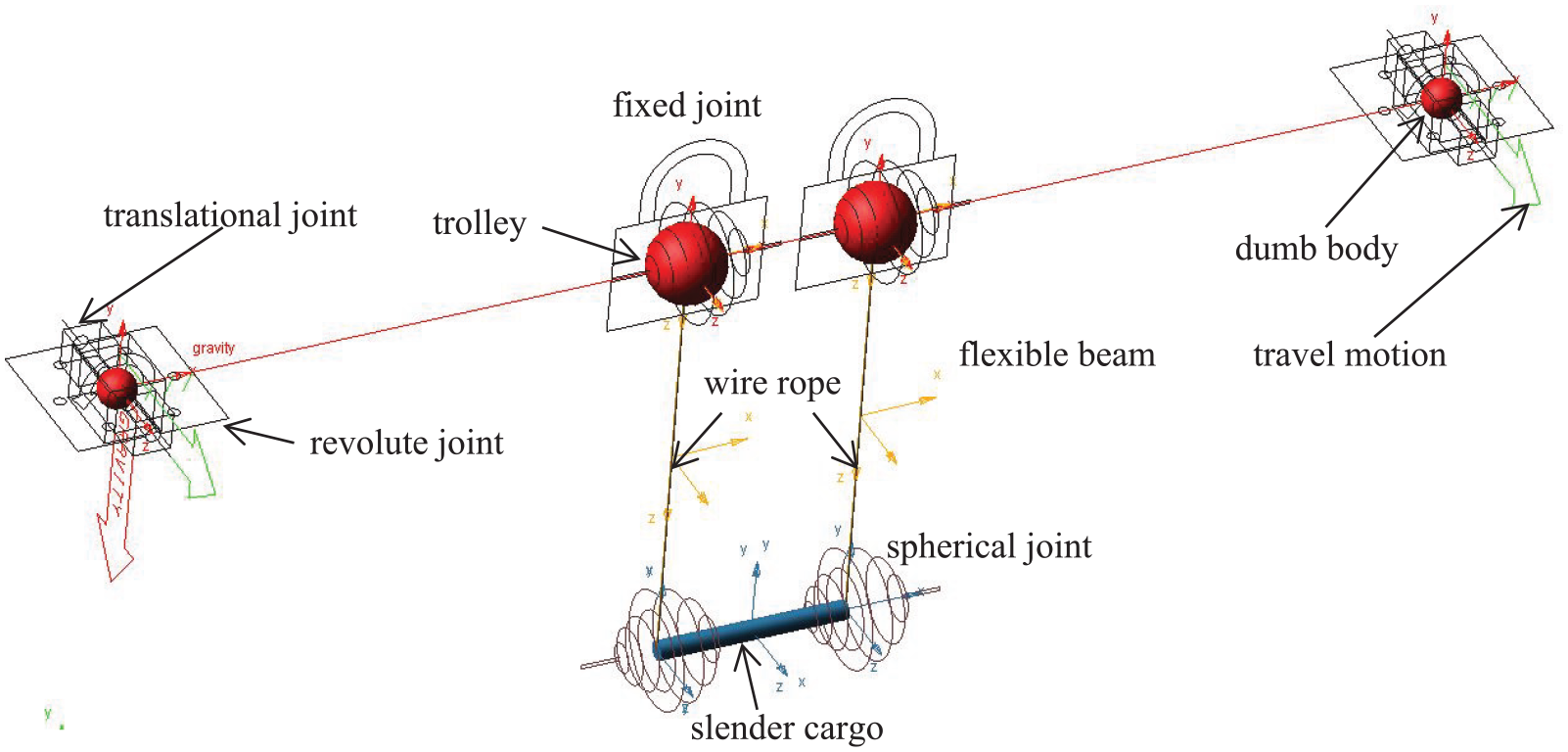
The prototype model of dual-trolley crane system in ADAMS.
Comparison of results
Only the time history curves of the in-plane angle, θ x , and the out-of-plane swing angle, θ y , calculated by the virtual prototype model and the presented analytic model, are illustrated in Figures 45 to 47. The stiffness of the main girder and the wire rope in the virtual prototype model are assumed large, and only the individual travel motion of the main girder is analyzed. Therefore, no matter how the pendulum length changes, the performance of the swing angle θ x is the same as that of the constant amplitude free swing, and the performance of the swing angle θ y is the same as that of the forced swing with the characteristics of “acceleration-uniform motion-deceleration.” The difference among the calculation results of the three pendulum lengths, Lp = 1/3, Lp = 1/2, and Lp = 1, is that, similar as the ordinary simple pendulum motion, when the pendulum length is small, the swing period of the curve becomes shorter; when the pendulum length is larger, the swing period of the curve is lengthened. By comparing the results from the two models, some conclusions can be drawn as follows.
The results for the in-plane and out-of-plane swing angles in case of Lp = 1/3 are depicted in Figure 45. Overall, the calculation results for the in-plane and out-of-plane swing angle agree well. In the figure, both the in-plane swing angle curves perform with almost constant amplitude, while the out-of-plane swing angle curves possess with the “acceleration, uniform-motion, deceleration” character. Although the amplitude of the curves is slightly different, the period agrees very well.
The results for the in-plane and out-of-plane swing angles in case of Lp = 1/2 and Lp = 1 are depicted in Figures 46 and 47, respectively. Compared with Figure 45, it can be found that both the in-plane and the out-plane swing angle curves in the two figures have similar characteristics to the curves in Figure 45. The most predominant difference of the results lies in the minor overshoot of amplitude. In addition, the period of the swing angle curve varies with the length of the wire rope in all cases.

The results of in-plane and out-of-plane swing angle in case of Lp = 1/3: (- - - - - -) the result calculated by virtual prototype model; (—) the result calculated by analytic model.

The results of in-plane and out-of-plane swing angle in case of Lp = 1/2: (- - - - - -) the result calculated by virtual prototype model; (—) the result calculated by analytic model.

The results of in-plane and out-of-plane swing angle in case of Lp = 1: (- - - - - -) the result calculated by virtual prototype model; (—) the result calculated by analytic model.
Conclusions
The dynamic process of dual-trolley overhead crane transshipping rigid-body cargo with degrees of spatial freedom was studied in this paper. Through the construction of a rigid-flexible coupling system model composed of beam, cable, point mass and rigid body, the effects of wire rope elasticity, main beam elasticity and payload mass on the motion of the cargo are analyzed, and the following conclusions are obtained.
When considering the elasticity of the system, the elastic variations of the wire rope and the girder will affect the motion of the cargo. This is because the elastic deformations of girder and wire rope behave as forced vibration term in equation (A.1); meanwhile, their second order differential terms behave as stiffness modulator in the stiffness matrix of equation (A.1). When they process with considerable magnitude, they will generate remarkable influence on both the amplitude and period of the swing angles.
The elastic effect is more significant in the process of individual travel of girder than in that of individual transverse of dual-trolley. This is due to that, in the transverse motion, the trolley and payload traverse along the girder rather than stay on the mid-span. The deformations of beam at the locations of the two carriages possess with similar amplitude and thus, they just cancel out the interactions. This leads to the influence of elasticity on payload swing become unnoticeable.
When considering the elastic influence of the system, the variation of the mass of payload will also have a significant impact on the motion of the cargo in the process of individual travel of girder. The influence of change of payload mass on its swing period is more significant than that on its amplitude. The period gets longer with increment of payload mass, that is, the heavier the payload mass the longer the period. However, in the individual transverse motion of the trolley, the influence of change of payload mass on the motion of cargo is not such obvious.
The fundamental purpose of this paper is to construct the governing equations of such a dual-trolley overhead crane transshipping rigid-body cargo. The calculation results can provide reference for the dynamic analysis and anti-sway control of dual-trolley overhead crane in case of large span, small stiffness and heavy load.
Supplemental Material
sj-pdf-1-ade-10.1177_16878140211031029 – Supplemental material for Influence of structural elasticity on transshipment dynamics of dual-trolley overhead crane
Supplemental material, sj-pdf-1-ade-10.1177_16878140211031029 for Influence of structural elasticity on transshipment dynamics of dual-trolley overhead crane by Xiaoguang Yao, Yongbao Feng, Lijun Meng, Liang Yao and Hongbin Li in Advances in Mechanical Engineering
Footnotes
Handling Editor: James Baldwin
Declaration of conflicting interests
The author(s) declared no potential conflicts of interest with respect to the research, authorship, and/or publication of this article.
Funding
The author(s) disclosed receipt of the following financial support for the research, authorship, and/or publication of this article: This work was supported by the National Natural Science Foundation of China (grant number 51505485), the Basic Research Program of Natural Science in Shaanxi Province (grant number 2020JM-640), the Special Item Funds for High-level Personnel of Xijing University (grant number XJ18B08), and the Youth Innovation Team of Shaanxi Universities.
Supplemental material
Supplemental material for this article is available online.
References
Supplementary Material
Please find the following supplemental material available below.
For Open Access articles published under a Creative Commons License, all supplemental material carries the same license as the article it is associated with.
For non-Open Access articles published, all supplemental material carries a non-exclusive license, and permission requests for re-use of supplemental material or any part of supplemental material shall be sent directly to the copyright owner as specified in the copyright notice associated with the article.