
Abstract
Stainless steel wire rope isolator is widely used in engineering. To optimize design of the isolator, loading, and unloading characteristics of the 6 × 19 6 mm wire rope under compression are investigated. Ropes of different lengths are tested to get the force-displacement relations. The stiffness, the equivalent damping ratio, and the hysteresis loop of the wire rope are derived. The stiffness decreases with both the length of the rope and the vibration amplitude. It has an approximate linear relationship with the reciprocal of length and amplitude. The equivalent damping ratio has an approximate quadratic relationship with the reciprocal of length and amplitude. The hysteresis loop of the wire rope is described using the proposed quadrilateral model. The loading stage is found to be determined by the length of the rope. The unloading stage is influenced by both the vibration amplitude and the length of the rope. Influences of the excitation amplitude and the frequency on the isolation performance for both steady-state vibration and transient impact vibration are revealed based on the models. The work would help engineers to design the isolators and predict responses of the structures.
Introduction
Vibrations and shocks are detrimental to the structures and equipment if they go beyond the tolerable limits. To protect the equipment and structures, vibration isolators often lie between the support base and the equipment or structures to reduce the vibration energy transmission of the support base. The vibration isolators can be divided into two categories: linear isolators and nonlinear isolators. For linear isolators, the stiffness and the damping ratio are constant. However, these isolators cannot provide isolation in the frequency range lower than its natural frequency. For this reason, the nonlinear isolators whose stiffness and damping ratio changes during the vibration have been widely studied.1,2
Wire rope isolators (WRIs) are a type of nonlinear isolators. They mainly consist of stainless wire ropes and two metal retainers. There are three types of traditional WRIs: T-type, G-type, and Q-type. 3 In addition, researchers have designed other types of WRIs according to specific working conditions such as YGG type, O type, limit type, etc.4–7
WRIs have lots of advantages. They can provide isolation in all directions. The damping characteristic of the WRIs is originated from the rubbing and sliding friction between the intertwined wires.8,9 It is not influenced by the vibration frequency.10,11 WRIs can work under temperatures between −100°C and 250°C. The mechanical properties of WRIs are not sensitive to salt, fog, grease, and dust. 2 These advantages make them widely used in ships,12,13 vehicles, 14 pipes, 15 and electrical equipment.16,17
WRIs exhibit a hysteresis behavior under cyclic loading. The hysteresis curve is symmetric for rolling and shearing loading while asymmetric for tension or compression loading. 9 The hysteresis curve could be described using different models such as the Bouc–Wen model, the revised Bouc–Wen models, the PHM model, and the bilinear model.9,18–22 However, the parameters of the models usually have no physical meaning, making them difficult to correlate with the structural parameters. 23
To optimize the design of the WRIs, researchers investigated the mechanical properties of the wire rope. Costello 24 and Velinsky 25 presented elastic theories to predict the stresses in the wire rope under axial, bending, and torsional loads. The studies show that the bending modulus and the tension modulus are different from the material’s Young’s modulus. Thus, the rope is not seen as a homogeneous material when there are combined stresses in the rope. As a consequence, the analytical modeling becomes very difficult. The finite element method has the advantage of geometric modeling of the wire rope. It is employed to analyze the mechanical properties of the wire rope. Ghoreishi et al. 26 and Jun et al. 27 examined the stresses in the wire ropes under axial loading using a finite element model. However, the analysis of the damping properties of the wire rope needs a much finer mesh of the rope to take into account the friction between the wires. It makes the analysis very time-consuming especially when there are large-scale structure models. Thus, Jiang, 28 Fedorko et al., 29 and Stanova et al. 30 only built the finite element models of a single strand.
To overcome the mechanical modeling difficulties of the wire rope, the nonlinear vibration performances of the 6 × 19 6 mm stainless steel wire rope under compression are investigated using the experimental method in this paper. The stiffness and the damping ratio of the wire rope are obtained. Their relations with the length of the rope and the vibration amplitude are established. Further, an asymmetric model is proposed to describe the hysteresis loop of the wire rope. The relations between the model parameters and the length of the rope and the vibration amplitude are then established. The findings in this paper would be helpful for the design of the WRIs.
Materials and methods
The tested wire rope is from the structure of 6 × 19 as shown in Figure 1. The nominal diameter of the rope is 6 mm. There are seven strands in the wire rope. The core strand is the same as the other outside strands. Each strand consists of 19 wires. The wires in the strand are distributed over three layers, one wire in the core, six wires in the mid-layer, and twelve wires in the outside layer. The material of the wire is 06Cr19Ni10 which is a kind of stainless steel. 31

Structure of the 6 × 19 wire rope: (a) front view and (b) section view.
Three specimens of the wire rope are prepared as shown in Figure 2. The lengths of them (L) are 275 mm, 432 mm, and 581 mm, respectively. The ends of the specimen are fixed in a rigid manner using buckles. The buckles are set on the testing machine by the upper holder and the lower holder as shown in Figure 3. The buckles are not allowed to rotate. It can move only along the x-direction to achieve a simple compression state of the wire rope isolator. The testing machine used is HS-3000A from Hesheng Instrument Technology Co., Ltd. The wire rope is located in the vertical plane. The initial shape is semicircular.
Tested wire rope isolator.

Fixture of the wire rope.
A compression load on the wire rope is applied by moving the upper holder of the wire rope downward and upward. The maximum displacement of the forced movement, the amplitude A is shown in Table 1. According to the typical nonlinear hysteresis characteristics of the WRI, the hysteresis performance of the wire rope is independent of the frequency.11,12 The moving speed of the holder is set to 60 mm/min. Figure 4 shows the deformation of the wire ropes at different displacements.
Moving amplitude A.

Deformation of the WRIs: (a) L = 275 mm, (b) L = 432 mm, and (c) L = 581 mm.
Results
The relations between the vertical force f and the displacement x of the wire ropes are shown in Figures 5 to 7.
Experimental f(x) of 275 mm rope.
Experimental f(x) of 432 mm rope.

Experimental f(x) of 581 mm rope.
Effective stiffness
Based on the experimental data, the effective stiffness of the wire rope can be obtained by the formula 31 :

Where fmax and fmin are the maximum and minimum force. xmax and xmin are the maximum and minimum displacement. The stiffness of the wire rope is shown in Table 2. It can be seen that the stiffness decreases when the length or the amplitude gets larger.
Effective stiffness k.

Let k have a linear relationship with the reciprocal of the length and the amplitude for all points:

Where a1, b1, and c1 are coefficients. They could be acquired using the least square method. a1 = 39.07 N, b1 = 0.8205 N, c1 = −0.0632 N/mm. The fitting surface is shown in Figure 8. The r2 is 0.99. The standard error is 0.0056 N/mm which is very small compared with the stiffness. This indicates equation (2) can describe the changes of the stiffness well.
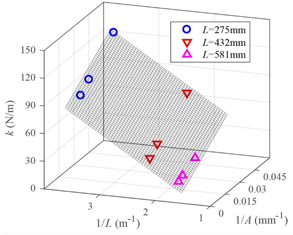
Surface fitting of k.
Equivalent viscous damping ratio
The equivalent viscous damping ratio of the wire rope ξ can be evaluated with the following equation 31 :

Where WD is the dissipated energy in a cycle of harmonic motion. It can be acquired by evaluating the area of the hysteresis loop in Figures 5 to 7. The obtained damping ratios are shown in Table 3.
Equivalent damping ratio ξ.
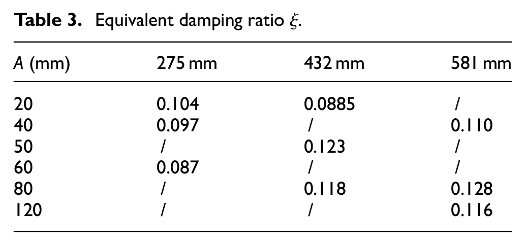
It can be seen from Table 3 that the damping ratio may increase or decrease with the length of the rope and the vibration amplitude. No apparent simple relations exist between them. Thus, the damping ratio is assumed to have a quadratic relationship with the reciprocal of length and the reciprocal of amplitude:

Where p1 = 0.08139, p2 = 47.69 mm, p3 = −1.238 mm, p4 = −1.576 × 104 mm2, p5 = 1162 mm2, and p6 = −36.71 mm2. The fitting surface is shown in Figure 9. The r2 is 0.95, and the standard error is 0.00553 showing the results agree well with the experimental data.

Surface fitting of ξ.
Hysteresis loop
A quadrilateral model is proposed to approximate the hysteresis loop of the wire rope. The quadrilateral curve OHMN is shown in Figure 10. The quadrilateral consists of the triangle OHM and the triangle MNO. O is the origin. Let the coordinates of the points be H (xH, fH), N (xN, fN), and M (xmax, fmax).

Quadrilateral model of the hysteresis loop.
Lines OH and HM correspond to the loading stage. The piecewise function of the lines can be expressed as:

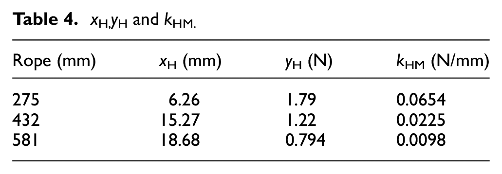
The f–x curves of each WIR under different loading amplitude basically coincide as shown in Figures 5 to 7. Only M changes with the vibration amplitude. Thus, the loading stage is described using the parameters xH, fH, and the slope of the HM line kHM. kHM can be written as:

The values of these parameters for each WRI are obtained by fitting the loading stage of the f–x curve of the largest amplitude using equation (5). They are listed in Table 4.
x H, y H and kHM.
Their relationship with the length of wire rope can be described by the quadratic polynomials:

Lines MN and NO correspond to the unloading stage of the vibration. The functions of the lines could be expressed as:

By fitting the unloading experimental data in Figures 5 to 7 with equation (8), the coordinates of N can be obtained. The slope of line ON kON, and the slope of line MN kMN are then derived as listed in Tables 5 and 6. It can be seen that kMN has a tendency to decrease with the amplitude and the length of the rope, while kON increases with the amplitude and falls with the length of the rope.
k ON.

k MN.

Let kMN and kON be functions of the reciprocal of the length and the reciprocal of the amplitude:

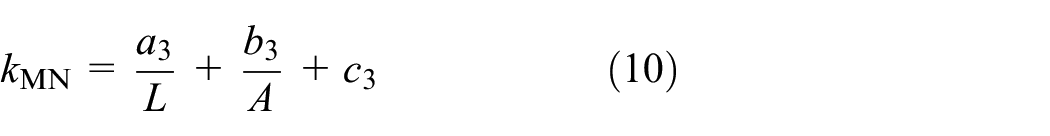
Coefficients for all points using the least square fitting method can be obtained. a2 = 24.79 N, b2 = 0.3908 N, and c2 = −41.63 N/m, a3 = 107.9 N, b3 = 0.6955 N, c3 = −131.3 N/m. The r2 for both fittings are 0.98, indicating equations (9) and (10) describe the characteristics of the unloading stage well.
The theoretical force-displacement relations of the tested wire ropes are shown in Figures 11 to 13. Based on the theoretical hysteresis loop, the theoretical stiffness and the theoretical equivalent damping ratio of the tests can be derived. Comparisons of the theoretical stiffnesses with the experimental ones are shown in Table 7. It can be seen that the relative errors are all smaller than 10%, showing the quadrilateral model can predict the stiffness well. Comparisons of the theoretical damping ratios with the experimental ones are shown in Table 8. The relative errors are all smaller than 20%. These comparisons indicate that the quadrilateral model can describe the hysteresis loop well.

Theoretical f(x) of 275 mm rope.

Theoretical f(x) of 432 mm rope.

Theoretical f(x) of 581 mm rope.
Theoretical error of k.

Theoretical error of ξ.

Discussions
If the WRI consists of the tested wire ropes and the ropes work under compression, the vibration performances of the WRI could be predicted with the built models.
Steady-state performance of the WRIs
When the WRIs work under the steady-state vibration situation, the transmissibility would be the priority target for design. It can be expressed as 31 :

Where

Where m is the mass of the supported structure,
However, the damping ratio

When A is smaller than Ac,
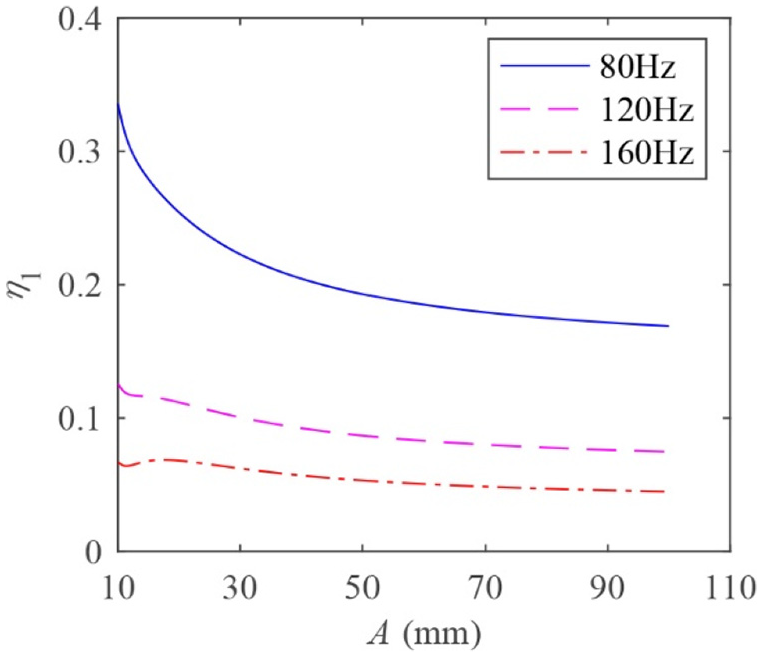
Let m = 0.1 kg, and the WRI consisted of only one 275 mm wire rope. According to equation (13), Ac is 24.5 mm. The transmissibility of the isolator is shown in Figure 12. It can be seen that when A is larger than Ac, η1 gets smaller. The results are in accordance with the theoretical analysis. When A is large enough, the transmissibility of the isolator decreases very slowly with A, as it can be observed. Figure 14 also shows that η1 decreases with ω. This relationship is similar to that of the linear isolators.
Steady-state transmissibility versus the vibration amplitude.
Figure 14 shows that when ω is small such as 80 or 120 Hz, η1 decreases with A even if A is smaller than Ac. However, when ω gets larger such as 160 Hz, η1 oscillates with A. This indicates that the influence of the amplitude on the transmissibility is larger than the damping ratio when the vibration frequency is small. The influence declines with ω when A is smaller than Ac.
The length of the wire rope has significant influences on the stiffness and the damping ratio according to equations (2) and (4). When designing the WRIs, the stiffness can be adjusted by the numbers of the ropes rather than the length of the rope. Thus, the length of the wire rope could be mainly chosen to meet the requirement for the damping ratio.
Transient performance of the wire rope isolator
For linear isolators, the transient response of them could be obtained using the Fourier transformation method. However, as the stiffness and the damping ratio of the wire rope are functions of the amplitude, the process is challenging to get the responses of the WRIs. Thus, there is a need to model the hysteresis loop of the wire rope. According to the characteristics of the force-displacement relations of the wire rope, the quadrilateral model to approximate the hysteresis loop is proposed.
For a single degree of freedom isolation system, the dynamic equation of the system can be expressed as:

Where x is the displacement of the supported structure. xb is the excitation displacement of the base. F is the restoring force of the isolator. F can be obtained using the built quadrilateral model.
If m = 0.1 kg and the isolator consisted of only one 275 mm wire rope, when there is a sinusoidal half-wave impact on the base, the displacement of the supported structure can be obtained by solving equation (14). The half-wave impact is expressed as:

Where ω0 is the excitation frequency of the base. It is set to be π initially. The results are shown in Figure 15. The first vibration period of the isolator is 4.4, 5.0, and 5.5 s when xb is 10, 20, and 30 mm, respectively. This means the vibration period becomes longer when the impact amplitude xb becomes larger. The transmissibility η2 (Ratio of displacement of the structure to xb) is 0.81, 0.62, and 0.55 when xb is 10, 20, and 30 mm, respectively. This means the performance of the isolator gets better when the excitation displacement gets larger.
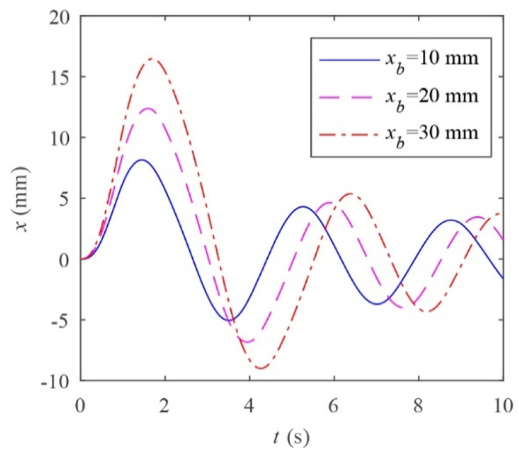
Displacement of the supported structure under sinusoidal impact.
The relationship between the transmissibility of the isolator and the excitation frequency of the base is shown in Figure 14. It can be seen η2 decreases rapidly when ω0 is small. Then it drops slowly with ω0. This suggests the WRI could work well in high-frequency impact situation. Figure 16 also tells that η2 decreases when xb increases. However, the influences of xb are insignificant. It indicates that the performance of the isolator is little influenced by excitation amplitude.

Transient transmissibility versus excitation frequency.
Conclusions
Nonlinear performances of the 6 mm 6 × 19 wire rope are investigated in this paper in order to help designers to optimize the WRIs. The following conclusions could be concluded:
The stiffness of the wire rope under compression has an approximate relationship with the reciprocal of length and the reciprocal of amplitude. The equivalent damping ratio of wire rope has an approximate quadratic relationship with them.
The hysteresis loop of the wire rope can be described well using the proposed quadrilateral model.
Steady-state transmissibility of the WRIs may decrease with the vibration amplitude and the excitation frequency. Transient transmissibility of the WRIs decreases with the excitation frequency. However, the vibration period gets longer with the excitation amplitude.
The work mainly focuses on the compression behaviors of the wire rope. Further studies are needed to fully understand the vibration characteristics of the WRIs in rolling and shearing.
Footnotes
Handling editor: James Baldwin
Declaration of conflicting interests
The author(s) declared no potential conflicts of interest with respect to the research, authorship, and/or publication of this article.
Funding
The author(s) disclosed receipt of the following financial support for the research, authorship, and/or publication of this article: The work is supported by the Senior Talent Foundation of Jiangsu University (15JDG038) and the Natural Science Research of Jiangsu Higher Education Institutions of China (19KJB130003).