
Abstract
This paper proposes a novel gas journal bearing in which orifices are different in diameter and distribute unevenly. Finite Difference Method (FDM) combined with Linear Perturbation Method (LPM) is used to solve the unsteady-state Reynolds equation of the flow field in the bearing clearance. Moreover, four types of bearing structures are used to discuss the effects of orifices different in diameter and uneven distribution on the bearing performance. The results demonstrate that the new bearing has better static and dynamic performances compared with those of traditional bearing in which orifices are equal in diameter and distribute evenly. Moreover, thin gas film thickness, high supply pressure, and large eccentricity ratio are hopeful for improving load capacity of the new bearing. Furthermore, the stability of the novel bearing is improved if eccentricity ratio is 0.25–0.3.
Keywords
Introduction
By using compressible gas as the lubricant for realizing non-contact rotary motion, gas journal bearing has many advantages such as approximate zero friction, high precision, high speed, no wear, and long life. It is widely used in the fields of large-scale mirror fly-cutting, microelectronics manufacturing, etc. The performance of gas journal bearing (the key component of the equipment) relates to the processing and manufacturing accuracy greatly. Although the bearing performance determined by the gas flow field (described by Navier-Stokes equation) in the bearing clearance, nearly all scholars used Reynolds equation to analyze the performance because of the difficulty of solving Navier-Stokes equations directly.
Li et al. 1 utilized Finite Difference Method (FDM) to solve Reynolds equation and employed Successive Over Relaxation (SOR) method in the iterations. Lo et al. 2 combined FDM and Rate Cutting Method (RCM) to solve Reynolds equation and the calculation was convergent if average gas film thickness was larger than 6 µm. In order to reduce calculation time, Zheng and Jiang 3 proposed a novel variable step iteration method when using FDM to calculate the performance of gas journal bearing and the iteration times was reduced greatly. Li et al. 4 concluded that FDM combined with flow-difference feedback was more suitable for solving Reynolds equation than FDM combined with SOR or RCM. Wang et al.5,6 combined FDM with Linear Perturbation Method (LPM) to solve unsteady-state Reynolds equation and analyze the effect of bearing parameters and manufacturing errors on the dynamic performance of gas journal bearing. Cui et al. 7 applied Finite Element Method (FEM) to discuss the influence of bearing parameters and manufacturing error on angular stiffness of aerostatic bearing. Sun and Gui 8 modified Reynolds equation for the gas journal bearing with misalignment caused by shaft deformation and analyzed the bearing performance by using FDM. Zhang et al. 9 studied the effect of misalignment of rotor and sleeve on load capacity and stiffness of gas journal bearing under pure-static and hybrid condition by using FDM. The results demonstrated that load capacity and stiffness improved with the increase of the degree of journal misalignment under hybrid condition, while the pure static condition was opposite. Yang et al. 10 discussed the effect of the numbers and locations of orifices on the performance of rotor-aerostatic bearing. They concluded that the bearing had better static and dynamic performance if there was an orifice located at the bottom of the bearing. Chen et al. 11 discussed the effect of the unbalanced aerostatic spindle on the manufacturing surface. The conclusion indicated that rotation speed and unbalanced spindle directly affected manufacturing surface topography. Hargreaves 12 improved load capacity of gas journal bearing by adding waviness inside sleeve surface. Moreover, they concluded that sine waviness increases load capacity significantly. Xiao et al. 13 discussed the performance of aerostatic journal micro-bearings (bearing diameter was 3–9 mm and orifice diameter was 0.08–0.14 mm) by using FDM. They concluded that aerodynamic pressure effect was more clear at ultra-high speeds and large eccentricities. Ishibashi et al. 14 concluded that the static and dynamic performance of small aerostatic bearing obtained by Computational Fluid Dynamics (CFD) method showed a reasonably good match with experiments. Wang et al. 15 discussed the influence of journal misalignment on the performance of gas journal bearing by using CFD simulations. They concluded that misalignment angle influenced dynamic stiffness coefficients clearly. However, it had little effect on dynamic damping coefficients. Cui et al. 16 studied the effect of manufacturing errors (waviness, taper, concavity, and convexity in circumference) on the static performance of gas journal bearing by using CFD simulations. Sharma et al. 17 concluded that gas journal bearing compensated by porous materials was helpful for improving load capacity, stiffness, and stability at high rotation speeds. Gao et al. 18 discussed the effect of chamber configurations on the performance of aerostatic thrust bearings by using CFD method. They concluded that the bearing with cylindrical chamber shape was helpful for improving load capacity and stiffness. Chen et al. 19 investigated the influence of spindle speed on the dynamic properties of aerostatic spindle systems according to CFD results. They concluded that rotational speed and rotation effects mainly impacted the tilting motion natural frequencies of the spindle. Lu et al. 20 reported that structure deformation could lower load capacity of aerostatic spindle by using CFD simulations.
This paper proposes a new gas journal bearing in which orifices are different in diameter and distribute unevenly to improve the bearing performance. FDM combined with LPM are used to solve the unsteady-state Reynolds equation of the flow field in the bearing clearance. Further, four types of bearing structures are used to analyze the effect of orifices different in diameter and uneven distribution on the bearing performance. This paper is organized as follows: Section 2 proposes the structure of a new gas journal bearing. Moreover, FDM combined with LPM is described for the performance calculation of the bearing. Section 3 discusses the effect of bearing parameters on its performance. Finally, the conclusions are given in the last section.
Bearing structure and performance calculation
Structure of a new gas journal bearing
The gas journal bearing with traditional structure is shown in Figure 1, in which two rows of orifices are equal in diameter and distribute evenly in the circumferential direction inside the sleeve. Where d, h, L, D, e, θ, and c are orifice diameter, gas film thickness, bearing length, bearing diameter, eccentricity, attitude angle, and average gas film thickness, respectively. y and z are the coordinates in the radial and axial directions, respectively. x is perpendicular to y and z simultaneously. L1 is the distance between bearing edge and orifice distribution circumference. Attitude angle θ relates to the centroids of rotor and sleeve. External pressurized gas enters the bearing clearance through orifices and forms gas film, then exhausts to atmosphere at bearing edge. The uneven gas film induced by eccentricity leads to gas pressure difference and enables the bearing support vertical load.

Gas journal bearing with traditional structure.
A new bearing structure is proposed in order to improve the bearing performance, as shown in Figure 2. The orifice diameter decreases from d1 to dn, etc. di+1 = di*γ, i = 1, 2, …, n − 1.

Structure of new gas journal bearing.
Performance calculation
Supposed the flow field is isothermal and laminar. 21 Lubricated gas is compressible and its viscosity is constant. The gas pressure distribution in the bearing clearance is governed by compressible Reynolds equation. 22
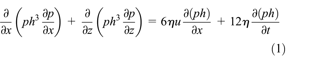
where p, t, and η are gas pressure, time, and gas viscosity coefficient, respectively. u is gas velocity in the x direction. Gas film thickness
Given

Supposed gas pressure is
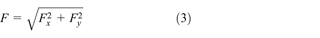
where Fx and Fy are load capacity in the x and y directions, respectively.


Attitude angle is calculated by

Given a linear displacement perturbation (ΔX, ΔY) to the rotor,


where P0 and H0 are dimensionless gas pressure and gas film thickness in the steady-state.
Substituted equations (5) and (6) into equation (2) and neglecting high-order terms. The perturbation equations about


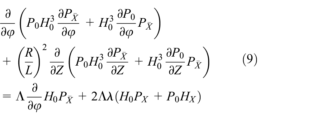

Equation (7) and equations (9), (8), and (10) are coupled equations, which can be solved by using SOR method.
FDM is used to solve the dimensionless Reynolds equation. In the calculations, the rotor curvature is not considered because bearing clearance is much small compared with bearing diameter. Therefore, the rotor surface is unfolded into a plane, as shown in Figure 3. M + 1 and N + 1 nodes are equally distributed in the x and z directions, respectively. Therefore, the calculation domain is divided into
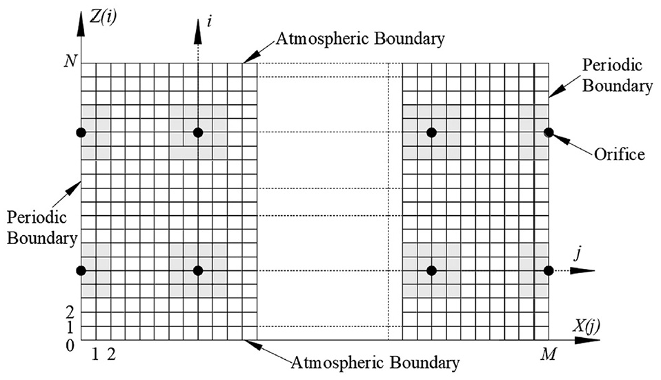
Unfolded rotor surface and mesh grid for FDM calculation.
The steady-state Reynolds equation can be discretized as following by using the second-order difference method.

where


The boundary conditions are as follows:
(1) Atmospheric boundaries,
(2) Periodic boundaries,
(3) The square of dimensionless gas pressure at node (i, j) where orifice located is

where
The partial differential terms of equation (7) at each grid satisfy the following equations.


Therefore,

where


Similarly, the solutions of
The boundary conditions of equations (7)–(10) are as follows:
Atmospheric boundaries, PX(i=0) = PX(i=N) = PY(i=0) = PY(i=N) = 0.
Periodic boundaries, PX(j=0) = PX(j=M), PY(j=0) = PY(j=M),


The dimensionless coefficients of dynamic stiffness and dynamic damping are
Therefore, the coefficients of dynamic stiffness and dynamic damping are
The stability characteristics of gas journal bearing is evaluated by two parameters
21
: critical inertial force (Keq)
c
and critical whirl ratio

The calculation procedure is shown in Figure 4. Finite Difference Method (FDM) combined with Linear Perturbation Method (LPM) is used to solve equation (2). Firstly, set bearing parameters and boundary conditions. Then, solve the steady-state Reynolds equation by using FDM and P0 and H0 are obtained. Thirdly, resolve the unsteady-state Reynolds equation by combining FDM with LPM and calculate load capacity, dynamic stiffness coefficients, and dynamic damping coefficients. Finally, calculate critical inertial force and critical whirl ratio.

Flow chart of static and dynamic performance calculation.
Results and discussion
In order to verify the correctness of the numerical method, the calculation results are compared with those of in reference 4. It indicates that gas pressure distribution and load capacity of present study are in good agreement with those of in reference 4, as shown in Figure 5.

Comparison of the results of present study and those of in Li et al.
4
(
The performance of four types of gas journal bearing listed in Table 1 is calculated. Structure I is the bearing with traditional structure whose orifices are equal in diameter and distribute evenly. The orifices of structure II distribute evenly while their diameters decrease from d1 to d5 gradually. The orifices of structure III are equal in diameter while distribute unevenly. Structure IV is the new bearing proposed in this paper in which orifices are different in diameter and distribute unevenly.
Bearing structures.

The bearings use gas as the lubricant. The gas characteristics and other parameters of the bearing are listed in Table 2.
Bearing parameters and gas characteristics.

The working parameters of the bearings are listed in Table 3. Case 1 analyzes gas pressure distribution on the rotor surface and load capacity of the four types of bearing structures. Cases 2–5 discuss the influence of eccentricity ratio, rotating speed, orifice diameter, and supply pressure on load capacity of the four types of bearing structures, respectively. Cases 6 and 7 analyze the effect of eccentricity ratio on the dynamic stiffness coefficients and dynamic damping coefficients of the bearings, respectively.
Bearing working parameters.

c = 12.5, 15, 17.5, 20, 22.5, 25, 27.5, and 30 µm in cases 2–5.
Gas pressure distribution and load capacity of different bearing structures
Figure 6 demonstrates the calculated results of case 1. Gas pressure distribution is symmetrical in the axial direction because of the symmetry of bearing structure while it is asymmetrical in the circumferential direction due to the aerodynamic effect when the rotor rotates. The maximum gas pressure is near the outlet of orifice 1 at where the bearing clearance is minimum. Moreover, gas pressure decreases from orifice 1 to orifice 5 gradually which generates load capacity because of the pressure difference in the bearing clearance. The pressure difference between adjacent orifices is enlarged in structure II, structure III, and structure–IV compared with structure I.

Gas pressure distribution and load capacity of the bearing with different structures: (a) structure I FI = 535 N, (b) structure II FII = 582 N, (c) structure III FIII = 596 N, and (d) structure IV FIV = 651 N.
Load capacities of structure I, structure II, structure III, and structure–IV are 535, 582, 596, and 651 N, respectively. Compared with structure I, orifice diameter gradually decreases from d1 to d5 in structure II improves load capacity 9%, from 535 to 582 N. Similarly, load capacity of structure IV is 9% bigger than that of structure III because orifices are different in diameter, from 596 to 651 N. Compared with Structure I, load capacity of structure III increases 11%, from 535 to 596 N because orifices distribute unevenly. Similarly, load capacity of structure IV grows 12% compared with structure II as orifices distribute unevenly, from 582 to 651 N. Therefore, the gas journal bearing in which orifices are different in diameter and distribute unevenly is helpful for improving load capacity. Compared with structure I, load capacity of structure IV increases 22%, from 535 to 651 N.
Effects of bearing parameters on load capacity
Figure 7(a) to (d) demonstrate the calculated results of cases 2–5, respectively. The figures indicate that load capacity of structure IV is obviously higher than those of other three structures. The order of load capacity from large to small of the four types of bearing structures is: structure IV, structure III, structure II, and structure I with the same eccentricity ratio.
Effect of bearing parameters on load capacity: (a) effect of eccentricity ratio, (b) effect of rotation speed, (c) effect of orifice diameter, and (d) effect of supply pressure.
Figure 7(a) indicates that eccentricity ratio affects load capacity greatly. The larger eccentricity ratio is, the higher load capacity is. The improvement of bearing structure on load capacity is obvious at thin average gas film thickness. However, it is negligible if average gas film thickness is larger than 22.5 μm at large eccentricity ratio.
Figure 7(b) demonstrates that bearing structure has obvious effect on load capacity at rotation speed of 5 krpm while the effect can be neglected at rotation speed of 20 krpm. Moreover, load capacity increases firstly and then decreases after it reaches the maximum value with the growth of average gas film thickness at low rotation speed while it decreases with increasing average gas film thickness at high rotation speed.
Figure 7(c) indicates that orifice diameter has little effect on the maximum value of load capacity. Moreover, the average gas film thickness corresponding to the maximum load capacity increases with the growth of orifice diameter.
Figure 7(d) shows that supply pressure influences load capacity significantly. The larger the supply pressure is, the larger load capacity is and the greater the influence of bearing structure on load capacity is.
Effects of bearing parameters on dynamic stiffness coefficients
The calculated results of case 6 indicate that eccentricity ratio influences dynamic stiffness coefficients greatly, as shown in Figure 8. Principal stiffness coefficients kxx and kyy increase with the growth of eccentricity ratio while cross-couple stiffness coefficient kxy is on the contrary. Furthermore, kyy changes more clearly than other dynamic stiffness coefficients with the increase of eccentricity ratio.

Dynamic stiffness coefficients with different eccentricity ratios: (a) effect of eccentricity ratio on kxx, c = 20µm, (b) effect of eccentricity ratio on kxx, c = 30µm, (c) effect of eccentricity ratio on kyx, c = 20µm, (d) effect of eccentricity ratio on kyx, c = 30µm, (e) effect of eccentricity ratio on kxy, c = 20µm, (f) effect of eccentricity ratio on kxy, c = 30µm, (g) effect of eccentricity ratio on kyy, c = 20µm, and (h) effect of eccentricity ratio on kyy, c = 30µm.
If average film thickness is 20 µm, as shown in Figure 8(a), (c), (e) and (g). kxx and kxy of structure II and structure III are higher than that of structure I while kyx is on the contrary. The orifice differenence in diameter and uneven distribution induce the growth of kxx and kxy. kyy of structure II is smaller than that of structure I while kyy of structure III approximates to structure I. Therefore, the orifice difference in diameter leads to the decrease of kyy while the effect of orifice uneven distribution on kyy is negligible. kxx and kxy of structure IV are larger than those of other three structures while kyx is on the contrary. Moreover, kyy of structure IV is smaller than those of other three structures at small eccentricity ratio. kxx, kyx, and kyy of four structures are positive while kxy is negative except the eccentricity ratio of structure IV is smaller than 0.3 at average gas film thickness of 20 µm. Therefore, the stability of structure IV is improved at small eccentricity ratio compared with that of other three structures because the bearing may be whirling unstable if
The sign of

If average gas film thickness is 30 µm, as shown in Figure 8(b), (d), (f), and (h). kyx of structure I is positive while those of structure II and structure IV is negative. kyx of structure III increases from negative to positive and decreases to negative again with growth of eccentricity ratio. kxy of structure I is negative while those of other structures decreases from positive to negative with the increase of eccentricity ratio. Therefore, the stability of structure IV and structure II is improved compared with that of structure III and structure I if eccentricity ratio is larger than 0.25.
Effects of bearing parameters on dynamic damping coefficients
The calculated results of case 7 demonstrate that eccentricity ratio influences dynamic damping coefficients significantly, as shown in Figure 9. The principal damping coefficients dxx and cross-couple damping coefficients dxy of structure II and structure III are larger than those of structure I at average gas film thickness of 20 µm. However, dyx and dyy of structure II and structure III are smaller than those of structure I. The orifice different in diameter and uneven distribution leads to the growth of dxx and dxy while dyx and dyy are on the contrary. Therefore, dxx and dxy of structure IV is larger than those of other three structures while dyy is on the contrary. Moreover, dyx of structure IV is smaller than those of other three structures if eccentricity ratio is small.

Dynamic damping coefficients with different eccentricity ratios: (a) effect of eccentricity ratio on dxx, c = 20µm, (b) effect of eccentricity ratio on dxx, c = 30µm, (c) effect of eccentricity ratio on dyx, c = 20µm, (d) effect of eccentricity ratio on dyx, c = 30µm, (e) effect of eccentricity ratio on dxy, c = 20µm, (f) effect of eccentricity ratio on dxy, c = 30µm, (g) effect of eccentricity ratio on dyy, c = 20µm, and (h) effect of eccentricity ratio on dyy, c = 30µm.
Dynamic damping coefficients can dissipate whirling energy. Compared with the effect of principal damping coefficients on whirling stable, the influences of cross-couple damping coefficients can be ignored. The whirling stability of structure IV is improved at small eccentricity ratio because the superposition of the effect of orifice different in diameter and uneven distribution. Therefore, the stability of structure IV is improved compared with that of other three structures especially at small eccentricity ratio.
The critical whirl ratio and critical inertial force of the four types of bearing structures are shown in Table 5 (
Critical whirl ratio and critical inertial force.

Conclusions
In this article, a new gas journal bearing in which orifices are different in diameter and distribute unevenly is proposed to improve the bearing performance. FDM combined with LPM is used to resolve the unsteady-state Reynolds equations numerically. Moreover, four types of bearing structures are used to discuss the effects of orifices different in diameter and uneven distribution on bearing performance. The conclusions can be summarized as following.
The small the orifice diameter is, the thinner average gas film thickness corresponding to the maximum load capacity is. Moreover, load capacity can be improved clearly by increase eccentricity ratio, rotation speed, and supply pressure at thin average gas film thickness. Further, the thinner average gas film thickness is, the more obvious the effect of rotation speed on load capacity.
The difference in orifice diameter and the uneven distribution of orifice has a superimposed effect on the static and dynamic performance of the bearing. In addition, the uneven distribution of orifice improves load capacity more than the difference in orifice diameter in small eccentricity and low rotation speed.
Compared with the bearing with traditional structure, the gas journal bearing compensated by orifices with different diameters and by orifices uneven distribution can improve load capacity 9% and 12%, respectively. The new gas journal bearing proposed in this paper increases load capacity 22%.
Average gas film thickness and eccentricity ratio influence the dynamic performance of the four types of bearing structures significantly. Moreover, principal stiffness coefficients and principal damping coefficients increase significantly with the growth of average gas film thickness. For the bearing with thin average gas film thickness, the smaller eccentricity ratio is, the better dynamic performance of the bearing is. However, the dynamic performance can be improved by increasing eccentricity ratio at thick average gas film thickness.
Supplemental Material
sj-pdf-1-ade-10.1177_16878140211028056 – Supplemental material for Numerical analysis on the performance characteristics of a new gas journal bearing by using finite difference method
Supplemental material, sj-pdf-1-ade-10.1177_16878140211028056 for Numerical analysis on the performance characteristics of a new gas journal bearing by using finite difference method by Yuntang Li, Ruirui Li, Yueliang Ye, Xiaolu Li and Yuan Chen in Advances in Mechanical Engineering
Footnotes
Appendix
Handling Editor: James Baldwin
Declaration of conflicting interests
The author(s) declared no potential conflicts of interest with respect to the research, authorship, and/or publication of this article.
Funding
The author(s) disclosed receipt of the following financial support for the research, authorship, and/or publication of this article: This work was sponsored by the National Nature & Science Foundation of China under grant 51675498 and 51905513, the Fundamental Research Funds for the Provincial Universities of Zhejiang under grant 2020YW29.
Supplemental material
Supplemental material for this article is available online.
References
Supplementary Material
Please find the following supplemental material available below.
For Open Access articles published under a Creative Commons License, all supplemental material carries the same license as the article it is associated with.
For non-Open Access articles published, all supplemental material carries a non-exclusive license, and permission requests for re-use of supplemental material or any part of supplemental material shall be sent directly to the copyright owner as specified in the copyright notice associated with the article.