
Abstract
A planar motion control system is proposed for autonomous vehicles not only to follow the lanes, but also to avoid collisions by braking, accelerating, and steering. The supervisor is designed first to determine the desired speed and the risk of the maneuvering due to road boundaries and obstacles. In order to allow lane changes on multi-lane roads, the model predictive controller is formulated based on the probabilistic non-convex optimization. The micro-genetic algorithm is applied to calculate the target speed and target steering angle in real time. A software-in-the-loop unit is constructed with the Rapid Control Prototyping device in the vehicle communication environment. The performance of the proposed system is verified for various collision avoidance scenarios and the simulation results demonstrate the safe and effective driving performance of autonomous vehicles with no collision on multi-lane road.
Keywords
Introduction
Autonomous vehicles have been proposed as a solution to problems related to car-to-car accidents due to increased traffic volume. 1 According to recent surveys, car-to-car crashes are the most frequent type of traffic accidents, requiring active safety technology and self-driving technology. 2 There is a growing demand for an autonomous vehicle system that covers the complicated situations such as lane change and collision avoidance. Even if many studies on path planning and control for Collision Avoidance (CA) have been conducted,3–15 these technologies are still in the development stage such as the complicated supervisor design including the risk assessment and CA controller design. Risk assessment is a method of determining the risk level of the object quantitatively. Collision avoidance is an operation that is initiated after the imminent collision is detected from the risk assessment.
The risk level assessment of the surrounding objects is very critical for the successful collision avoidance. In many risk assessment studies, the Artificial Potential Field (APF) method has been often utilized.3,9,12–14,16 APF is based on an energy field to express physical force or risk probability for obstacle avoidance in robotics since 1980.16–19 Recently, the APF concept is applied for optimal path planning and control in the automotive field.7,9,12,13,15 For instance, Ji et al. 12 proposed a trajectory planning in the optimal gradient direction of the potential field. This method can calculate the route quickly, but, there is a possibility that the calculated path does not consider the dynamic characteristics of the vehicles. Rasekhipour et al. 13 defines two kinds of the obstacle APF: crossable and non-crossable object APF based on the amplitude of the APF. Because they utilized the linear programming solver for approximating the nonlinear objective function, the distortion of the risk assessment is inherent. In addition, geometry-based risk functions have been suggested for the CA problem.6,7,20,21 Werling and Liccardo 6 formulated the risk assessment by taking into account the minimum distance to the object. The advantage of this method is that it quickly determines collision-free maneuvering by predicting the future risk with the vehicle model. Rosolia et al. 20 defined the collision risk with oval which covers entire vehicle. Since the collision risk is differentiable, the oval collision risk is suitable to linear programming solver. Li et al. 21 decomposed the vehicle shape by circles which cover the vehicle entirely and checked the distance between the circles on the ego vehicle and the circles on the obstacle vehicle. The advantage of these methods is that the collision risk can be easily checked by simple approximation. But, these methods assume simple vehicle shape such that the shape of risk can be different from the actual vehicle.
Among the various CA controllers, model predictive control is the most actively utilized.6,7,13,15 Its ability to handle the actuator capacity and the output constraint is crucial despite the burden of computation time. In particular, unlike the conventional control techniques, it is possible to design specific and descriptive scenarios using MPC conditions. Rasekhipour et al. 13 suggested Sequential Quadratic Programming (SQP) based MPC to calculate steering angles and target speeds considering the APF risk model. However, in order to implement QP MPC control, the objective function needs to be a convex function and the constraint should satisfy the convex set. 22 In actual road conditions, however, situations may exist that cannot be easily described by convex optimization. For example, as shown in Figure 1, path A has wider free space than path B and the ego-vehicle (blue) can avoid collision more safely by taking path A if the next lane is empty. However, path B would be the CA result of convex optimization because the ego-vehicle is driven on the second lane before the CA action and path B is relatively closer. In addition, convex optimization can consider the action near the local minimum and the determined action cannot be changed to another optimal action. Thus, in theQP-based optimal controller, it may be difficult to use the non-convex functions as the risk function.

Planar control problem that convex optimization does not solve well.
To process the non-convex formulation without approximation, an optimization tool is needed to find the global optimal point for the CA problem. Among the candidate solutions, there exist gradient-free search methods such as genetic algorithm, particle swarm algorithm, and pattern search algorithm.23–26 However, many of the global optimization methods are not proper for real-time control task of autonomous vehicles, since these methods have high computational complexity as mentioned in Fleming and Fonseca
27
and Wang et al.
28
Because of the difficulty in archiving real-time performance, other techniques have been investigated with multicore CPU.28,29 While the above global optimization techniques involve significant computational burden, the CA with micro-genetic algorithm (
In this study, an autonomous driving system for normal driving and collision avoidance is proposed based on nonconvex optimization and the MPC. At first, a supervisor is described to predict the collision risk and desired speed. The risk functions of road boundary and vehicles are modeled using different mathematical functions. In particular, the Gilbert-Johnson-Keerthi (GJK) algorithm
30
is simplified to detect the obstacle collision with less computational complexity. Also, the motion of the surrounding vehicles and the desired speed of the host vehicle are predicted along the road geometry. Considering the planar motion of the host vehicle, a non-convex optimization problem is defined for the Gaussian objective function of the collision risk and reference input. Finally, the optimal problem is solved by using the modified
-Multi-reference control formulation is proposed based on the non-convex optimization such as speed tracking, lane keeping, and collision avoidance by decelerating or changing lanes for autonomous driving
-The GJK algorithm is simplified for less computation burden and utilized to assess the collision risk between vehicles
-The
Planar motion control system configuration
The planar motion of the autonomous vehicle is determined by two inputs: steering angle and longitudinal speed. It is assumed that the autonomous vehicle is equipped with a speed control module such as Adaptive Cruise Control (ACC). The surrounding information such as lane markers, vehicles, and obstacles is also assumed available through in-vehicle sensors. The lane information is assumed to be provided in the form of a cubic polynomial with respect to the host vehicle. 31 The practical issues such as sensor uncertainty are not considered in this formulation. In addition, the motion data of the vehicle is assumed to be available either by vehicle network or by estimation.
The block diagram in Figure 2 shows the structure of the planar motion control (PMC) system. The proposed PMC system is composed of supervisor and MPC controller. The purpose of the supervisor is to obtain the collision risk and to determine the maximum speed for the given road environment. The input to the supervisor is the information of the road and the surrounding vehicles. The supervisor is constructed by utilizing the risk models along the predicted trajectory of the host vehicle and provides the collision risk on a geometric basis and the desired speed of the host vehicle. The MPC is constructed based on the objective function consisting of the collision risk of the obstacles and the maneuvering command. Non-convex optimization problem is solved for the steering angle and the target speed by utilizing the

Planar motion control system architecture.
Supervisor design
Risk modeling for the surroundings and collision prediction
Based on the relative position of road boundaries and obstacles, the corresponding risk can be expressed in the form of a specific function. The risk of the road boundary is described as a function having the maximum value near the boundary with a shape close to the cumulative normal distribution.
32
The risk of road boundaries,

where
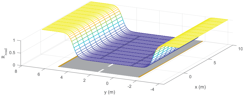
Risk of 2-lane road boundary where
In addition, predicting the behavior of the surrounding vehicles along the road is also crucial to the collision detection. The typical motion prediction model is the Constant Velocity (CV) model and there have been several studies predicting the future position of the surrounding vehicles with this model. 8 Another motion prediction model is Constant Turn-Rate and Acceleration (CTRA) model 34 which is suitable in a curved road. However, CV model may not be suitable to describe the vehicle motion on the curved road. In addition, as shown in Figure 4, the CTRA model can not be utilized in the lane change motion prediction, in particular, for a long prediction horizon. Thus, either of these models is not suitable for predicting lane-change as well as lane centering motions.

Limitation of CTRA model in the lane change motion prediction.
In order to predict the future position of the surrounding vehicles better and to describe the correlation between the vehicles and the road, the APF method is used with adjusting the vehicles motion to the descending direction of the slope of the risk function.3,9,12 While the repulsive potential from the road boundary is considered in the road boundary risk (1), the attractive potential to the center of the lane needs to be considered. In order to include the lane change motion of the surrounding vehicles, the bounded attractive potential field is utilized instead of the unbounded one. Then, if the momentum caused by the lateral speed becomes large enough to escape the attractive force of the current lane, the surrounding vehicle is predicted to move to the adjacent lane. The attractive potential to the

where

where
The purpose of this method is predicting the lane where surrounding vehicles would travel, rather than predicting the accurate future position of the surrounding vehicles. That is, it gives us the criterion that prevents the host vehicle being steered toward adjacent lanes where the surrounding vehicles are expected. For instance, the result of predicting cut-in vehicle trajectory is depicted in Figure 5.
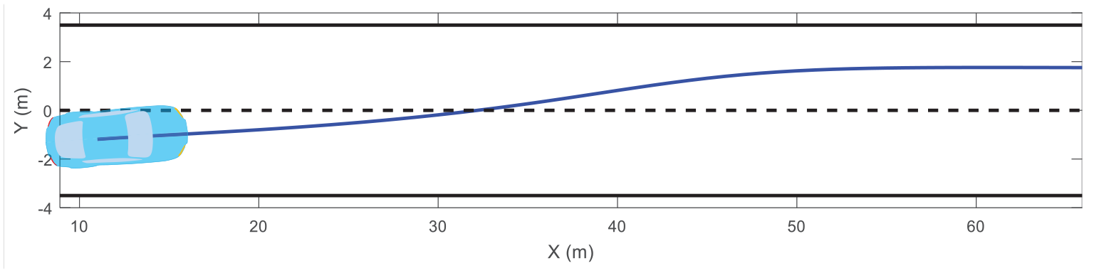
Trajectory prediction of the surrounding vehicle in cut-in scenario.
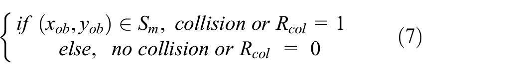
In order to judge collision on the predicted trajectories of the host vehicle, the collision between vehicles is interpreted in two-dimentional space and, the vehicle shape is described as a rectangle. Based on these assumptions, the collision between vehicles is simplified as the collision between two rectangles. There exist algorithms that can detect the collision between polygons.30,35–37 Among the algorithms, GJK algorithm has low computational cost for real-time application. 30 In this study, the GJK algorithm is utilized to represent the collision risk as a rectangular shape. In addition, the GJK algorithm is simplified for even less computational complexity. Conventionally, the collision risk has been typically described as circular or oval shape based on artificial potential field, but its shape includes unnecessary risk region and it can cause conservative warning and evasive maneuvering.
GJK algorithm detects collision based on the Minkowski Difference (MD) which is defined as a set of the difference between the position vectors of one polygon and the others. In case of a point-symmetric polygon, like a rectangle, it is also the same problem of whether the MD contains the origin of the surrounding vehicle as shown in Figure 6. Here, the Minkowski difference,

where

Collision detection using reduced GJK algorithm.
In order to detect the collision with the original GJK,
30
it is necessary to check whether the simplex defined by the vertices of the MD contains the origin. But, this process is computationally burdensome, and thus, in this study, MD is replaced with

where

where
Then, collision can be expected using the following condition
Even if the simplified GJK algorithm shows less computation burden than the existing collision check algorithms, it takes longer time to check the collision risk of all the detected objects. Thus, the proposed system is designed to activate the collision detection algorithm only in necessary situations such as imminent collision. The activation threshold is set such that the object is expected to approach within 10 m radius of the host vehicle in the prediction horizon of 1 s.
Desired speed determination
Since the longitudinal dynamics affect the lateral motion of the vehicle, determining the maximum longitudinal velocity affects the performance of the PMC system. Firstly, the vehicle should follow the set speed well. Secondly, the vehicles desired speed should be adjusted depending on the curvature in cornering. For example, in order to maintain the turning radius with a constant speed, the lateral force equivalent to the centrifugal force is required. Therefore, the desired longitudinal speed at the curved road is related to the maximum lateral acceleration,

Assuming that the vehicle follows a path with a little side slip, the lateral acceleration can be approximated as follows:

and the limit of the longitudinal speed is determined. 38
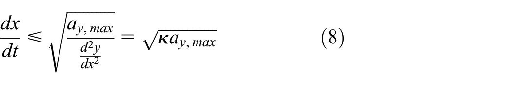
where
Then, the desired speed is determined from the following equation where the desired speed at the curve is set to only 80% of the above speed limit for safe driving.

where
Non-convex model predictive controller design
In this section, a model predictive controller is formulated based on the
Planar vehicle dynamics
For the simplicity of the MPC design, the following lateral dynamic model is utilized. 39

where
As described by Jazar, 39 the lateral force can be approximated by a linear function of the wheel slip angle which can be expressed based on the geometric relationships at front and rear

where
For the longitudinal motion, commercial speed controllers such as ACC (Adaptive Cruise Controller) are assumed in this study and the longitudinal speed control system is approximated by the first-order delay model.

where
In order to represent the dynamic characteristics described in the differential equations (10)–(12) into the global coordinate


By defining the state variables as follows:

Equations (10)–(13) can be expressed into a non-linear state equation with steering angle and target speed as input.


where

where
Non-convex MPC formulation and modificationof
-GA for real-time performance
In this section, a non-convex optimization-based MPC algorithm is designed with a prediction horizon. Firstly, multiple control objectives are defined using a probabilistic function such as lane centering, desired speed tracking, and collision avoidance. Secondly, the formulation for collision avoidance task is proposed considering the real-time performance.
The optimization problem is formulated similar to the conventional MPC, 40 but is converted to the gaussian function formulation.
where
In normal driving case, following the lane center and the desired speed are very important. For the lane centering, the tracking reward of the host vehicle position is described with respect to the center of its own lane:

where
For multi-lanes, the positional probability can be expressed as follows:

where
For the following of the desired speed, its probability is also considered as follows.

By combining the lane following probability (19) and the desired speed following probability (20), MPC object function for normal driving is formulated.

For normal driving case, the target steering angle and speed are determined for the prediction horizon,

where the superscript * represents the optimal or sub-optimal value. This formulation allows the vehicle to change the lane as it travels with following the target speed.
For Collision Avoidance (CA), the control system should consider not only the collision risk, but also the lane keeping and driving at the desired speed. If various driving situations are considered, joint probability for every situation needs to be included and its computation demand can be very extensive. Instead, the following cost function is proposed in this study with less computational load.

Thus, for collision avoidance case, the target steering angle and the speed are determined as follows for the prediction horizon. Because the CA is much more important than the reference tracking,


Collision risk rule for vehicle crashes.
The prediction horizon can be varied depending on the speed. The maximum
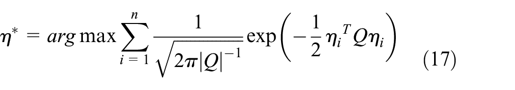
The non-convex optimization problems of equations (22) and (24) are solved by utilizing the

where

where
Configuration of
Similarly, the limit of the target speed (

where
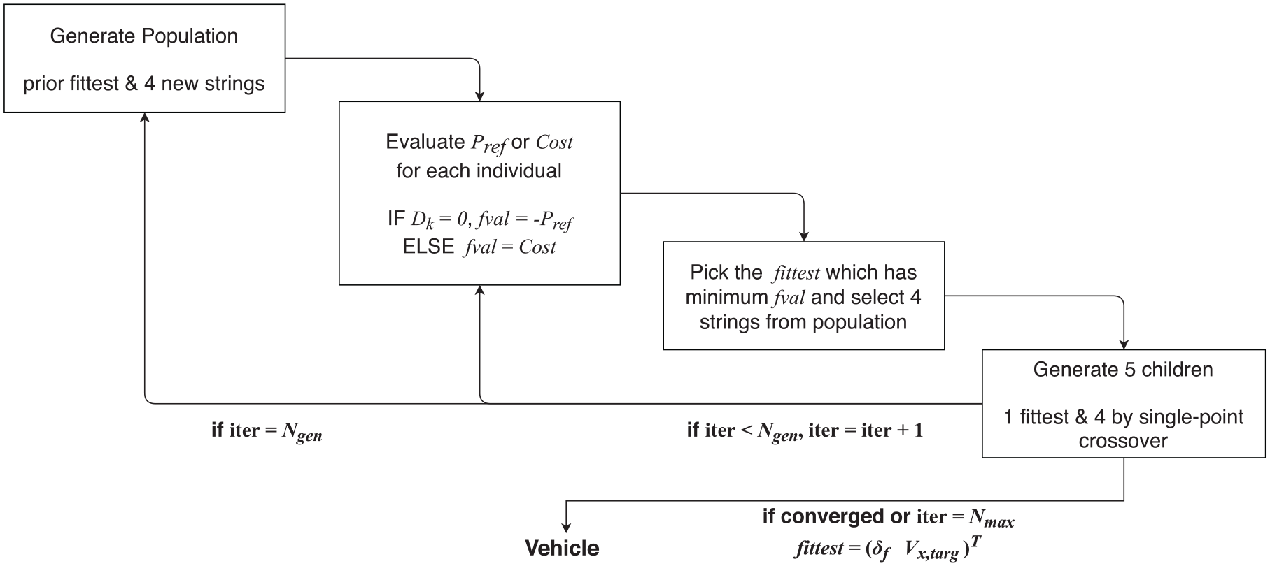
The initial population (
Step 1: Divide the search space of the target speed and the steering angle into three parts separately, and create a 3 × 3 grid map.
Step 2: Number the index of each point of the grid map sequentially (
Step 3: Select the index of sample point as
where randperm is an operator that computes the permutation of natural numbers from 1 to 4. The

This approach selects the initial population efficiently and reduces the iterations of the solver. For each population, the tracking probability (21) or the cost function (23) are calculated along the trajectory of the vehicle and the fittest individual is defined with the smallest cost among the population. In this case, the steering angle of an individual is increased or decreased step by step as the horizon proceeds by considering the slew rate of the steering angle.

where
Next, two pairs of parents are chosen in the population through the tournament selection and their overlap is allowed. A pair of parent generates two children using the single-point crossover and a new population of five entities is formed including four children and the fittest individual. In this study, five populations are selected best by considering the trade-off between computational volume and optimization quality. After it converges sufficiently to the local minimum through seven iterations, four entities are newly selected using the equation (27) with the fittest individual. This process is repeated until the convergence criterion is met and the fittest individual is determined as the optimal control input for
Results
To verify the performance of the proposed PMC (Planar Motion Control) system, a number of simulations have been conducted on several scenarios. A cooperative simulation tool has been constructed using software-in-the-loop system: rapid control prototyping unit and high-fidelity vehicle dynamics software. The vehicle model and PMC system parameters are listed in table in the Appendix. The road geometry parameters and traffic information are acquired at every 50 ms. The dynamic states of the host vehicle are transmitted through CAN bus at every 10 ms. The control time step is set to 50 ms.
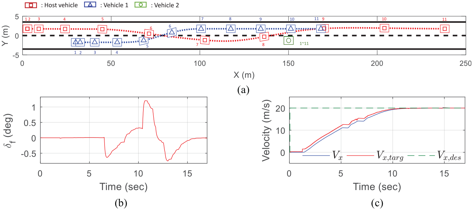
In the first scenario, the host vehicle accelerates from 0 to 20 m/s on a straight roadway with two lanes. A surrounding vehicle is traveling at 27.8 m/s from 150 m behind. This scenario is one of the common rear-end collision situation on the highway when the driver of the rear vehicle does not pay attention or fall asleep. The simulation results are shown in Figure 9. Trajectories of the vehicles are indicated by dotted line and markers are numbered to represent the simultaneous position of the host vehicle and the vehicle rushing from rear. Also, vehicle edge is described as a rectangular.
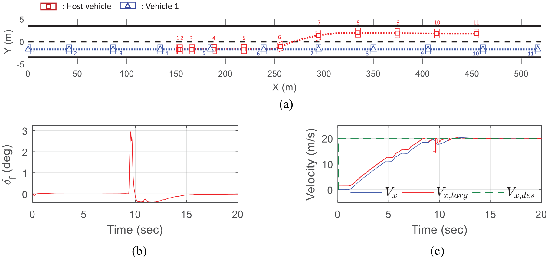
Scenario 1. (a) Trajectories of the host vehicle (red) and obstacle vehicle (blue) coming from behind (b) Steering angle (c)
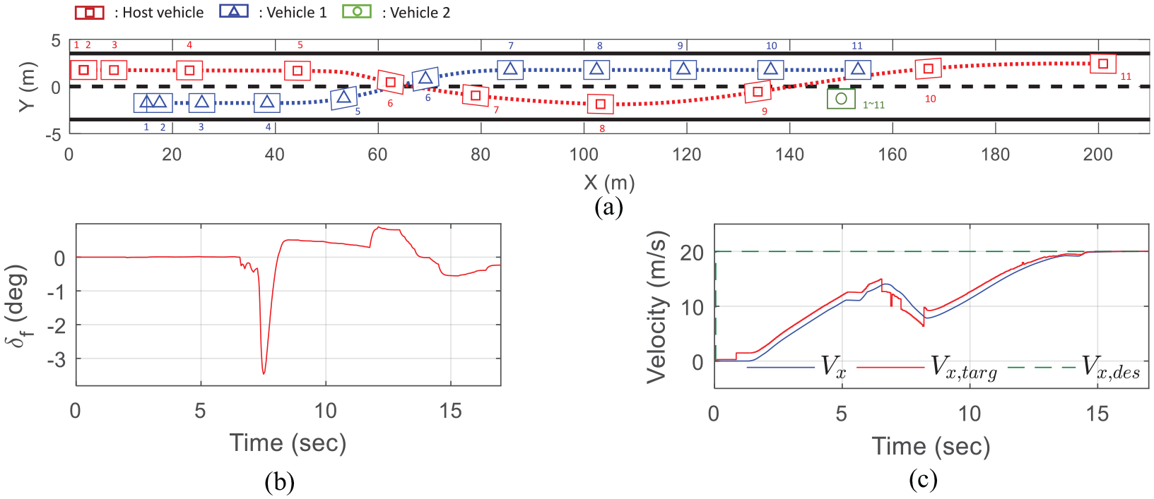
In the second scenario, two cases of the cut-in are considered. The scenario 2-1 is a situation where CA (Collision Avoidance) is possible by steering alone, and the scenario 2-2 is a case where not only steering, but also deceleration should be engaged. Also, to verify the robustness against the local minima problem, the second obstacle lies with the offset of 0.5 m to the left side of the center line of the lane. In both scenarios, the host vehicle accelerates from 0 to 20 m/s on a straight roadway with two lanes. In scenario 2-1, the obstacle vehicle 1, 30 m ahead in the adjacent lane, is accelerated from 0 to 10 m/s and performs cut-in into the ego lane. Then, the host vehicle confronts a stationary vehicle (obstacle vehicle 2) at 150 m ahead. Simulation results of scenario 2-1 are shown in Figure 10. Since a distance to avoid the vehicle 1 by steering is sufficient, the cost decreases fast during CA maneuver. The proposed controller demonstrates that the host vehicle avoids the collision by a lane change to the left lane instead of steering to the narrow space on the right side of the vehicle 2. In scenario 2-2, all conditions are same except that the obstacle vehicle 1 starts accelerating from 15 m ahead of the host vehicle and the results of Scenario 2-2 are shown in Figure 11. At 7 s, the obstacle vehicle 1 suddenly changes the lane and rushes to the host vehicle, so that the collision can not be avoided by the steering alone. Therefore, the host vehicle is steered and decelerated to avoid collision with vehicle 1. After that, the vehicle starts to accelerate again and reaches the target speed. Then, the host vehicle is steered to the left lane and avoid clash with the obstacle vehicle 2.
Scenario 2-1. (a) Trajectories of the host vehicle (red), obstacle vehicle 1 (blue) and 2 (green) (b) Steering angle (c)
Scenario 2-2. (a) Trajectories of the host vehicle (red), obstacle vehicle 1 (blue) and 2 (green) (b) Steering angle (c)
In the third scenario, the host vehicle accelerates from 0 to 20 m/s on a curved roadway with two lanes. The obstacle vehicle is located at 30 m ahead of the adjacent lane and performs cut-in motion with 10 m/s speed. The control performance is illustrated in Figure 12. The host vehicle avoids collision with the cut-in vehicle by changing lane to the right and the host vehicle accelerates to the desired speed. Because there is a stationary vehicle at 150 m ahead, the host vehicle changes lane back to the left lane. More over, the host vehicle slows down to follow the curved road for lateral stability. In the curved roadway, unlike straight one, since the PMC system determines steering effort considering the road geometry, the host vehicle avoids collision with less steering effort in some road sections.
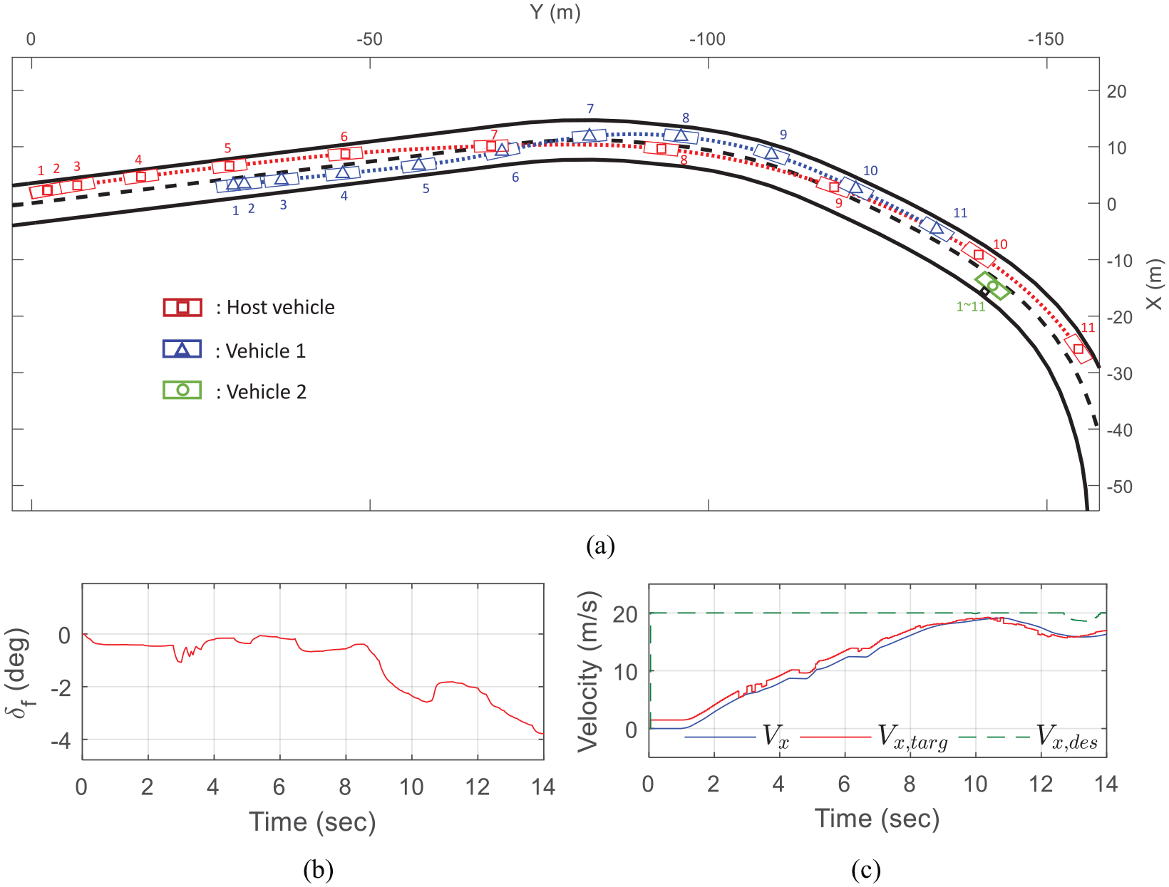
Scenario 3. (a) Trajectories of the host vehicle (red), obstacle vehicle 1 (blue) and 2 (green) (b) Steering angle (c)
In the fourth scenario, the host vehicle drives through the handling course with various curvature as illustrated in Figure 13. The initial position and speed of the vehicles are also represented in Figure 13. During driving along the road, the host vehicle confronts multiple obstacle vehicles and need to follow the curved road with no collision. The obstacle vehicles travel with slow speed or are stopped on the roadway. The host vehicle should overtake the slow vehicles if necessary and avoid the stopped ones. This scenario mainly considers overtaking slow vehicles on the local road with light traffic. Since there are some winding road sections, the target speed as well as the desired speed are adjusted for the host vehicle to decelerate properly and to maintain its position inside the roadway as shown in Figure 14. Also, the host vehicle changes lanes with an effective steering maneuver to overtake the slow vehicle, to avoid collision and to follow the curved road geometry.

The location and speed of the vehicle in scenario 4: Indexing the vehicles on the test road (initial X position, initial Y position, longitudinal speed).

Scenario 4 results. (a): Trajectories of the vehicles in scenario 4 at 25–40 s: the host vehicle (red square), obstacle vehicle 4 (blue triangle), 5 (green pentagram), 6 (magenta inverted triangle), and 7 (indigo circle). (b): Trajectories of the vehicles in scenario 4 at 50–65 s: the host vehicle(red square), obstacle vehicle 8 (blue triangle), and 9 (green pentagram). (c): Steering angle (d)
Conclusion
In this paper, an autonomous vehicle motion control system is proposed of non-convex optimization based model predictive control (MPC) system for collision avoidance and lane following. In the MPC design, a nonlinear model of vehicle maneuvering is used for optimization without the gradient. For this, the MPC is designed to allow the lane change freely through the probabilistic formulation of multi-reference tracking. The risk penalty of collision is directly applied to the cost function such that the host vehicle can avoid the surrounding vehicles by steering and acceleration.
The performance of the proposed system is evaluated in a vehicle communication environment with the software-in-the-loop system. Computation time of one control step is measured around 15 ms in average, but sometimes 30 ms in the worst case. The presented PMC system is capable of both lateral and longitudinal control, and, in particular, the longitudinal control is actively engaged for collision avoidance and overtaking. The simulation results demonstrate that the proposed system avoids collision by braking, accelerating, or steering for various curved roads with obstacle vehicles.
Footnotes
Appendix
Handling Editor: James Baldwin
Declaration of conflicting interests
The author(s) declared no potential conflicts of interest with respect to the research, authorship, and/or publication of this article.
Funding
The author(s) disclosed receipt of the following financial support for the research, authorship, and/or publication of this article: This work was supported by the Technology Innovation Program (10079730, Development and Evaluation of Automated Driving Systems for Motorway and City Road and driving environment) funded by the Ministry of Trade, Industry & Energy (MOTIE, Korea).