
Abstract
Modern engines in general waste plenty of heat to the exhaust gas and coolant. Considering that daily driving consists of frequent cold start, idling, and part load driving within short driving distances, the potentials to recover heat from high enthalpy exhaust gas are limited. In recovering heat from low enthalpy exhaust gas, a low thermal inertia exhaust heat recovery unit (EHRU) with no heat transfer fins is proposed to be integrated to the simplified split cooling circuit used in the earlier studies. This lightweight, compact and simple EHRU concept made of machined steel plate is targeted for naturally aspirated engines that are still being widely used worldwide. Cooler coolant feed from the bottom of the cylinder block’s water jacket rear end provided large temperature difference between the coolant and exhaust gas. In evaluating its effectiveness in speeding up the recovered heat availability for reuse, a 1.3 l passenger car equipped with strategically placed multiple thermocouples and flow meters was tested using NEDC test. From the experiments and classical analysis, the recovered thermal energy was available in just 25 s after cold start. The study also provided a new direction on the design of EHRU and its integration into an engine.
Keywords
Introduction
Ever since the introduction of heat engines hundreds of years ago, improvement in thermal efficiency is mostly dependent on how much heat that can be prevented from being wasted through the exhaust tailpipe and coolant radiator. 1 In view of the constantly improving thermal efficiency of internal combustion engines, such efficiency has gone up above the 50% barrier for both the spark ignition and compression ignition engines.2,3 The high thermal efficiency generally reduces the average exhaust gas temperature, thus making it more challenging for the exhaust heat to be recovered and converted to electrical or kinetic energy. Nevertheless, the potentials for the exhaust heat to be recovered to minimize it from being wasted are still high especially from the low enthalpy exhaust gas during cold start, idle and part load operations. Even if the low-grade heat is not convertible to other form of energies, it contains precious thermal energy that shall not be wasted. 1
Roberts et al. 4 have compiled many studies by others about the various driving trends in major markets and how quick powertrain warm-up and high exhaust gas temperature availability have been lacking. In overcoming the limited exhaust gas exergy and enthalpy availability, many researchers have stepped up the research in recovering the exhaust heat to expedite the warm-up of powertrain’s fluids and metals.5–12 These fluids consist of the engine coolant, engine oil and transmission oil. The combination of the fluids and metals present large thermal inertia and requires as much as 60%–65% of thermal energy to overcome the thermal inertia in the early phase of cold start.13,14 The sooner the fluids and metals get into the optimum temperatures and stay within the recommended ranges, the lesser the intake port wall wetting, combustion heat quenching,4,11,12 and parasitic losses6-10,15,16 will negatively impact the fuel consumption throughout the vehicle operations.
Goettler et al. 17 installed an EHRU to a 3.3 l spark ignition engine and investigated the coolant warm-up time and fuel consumption during highway and city driving. The EHRU reduced the coolant warm-up time and fuel consumption by 7% and 2.2%, respectively during idle and 16% and 2.2%, respectively during highway driving. Andrew et al. 18 evaluated the effects of combined exhaust-to-coolant EHRU and 6 kW engine oil heater to warm-up time and fuel consumption using Ford 1.4 l spark ignition CVH engine. From the study, at 35% peak load and 2000 rpm engine operation, the oil warm-up time was reduced from 10 to 3 min and the fuel consumption was improved by 12%–15% during the first 7 min of cold start.
Without doubt, the research in this area has much greater potentials for quick applications to mass production. In particular, the EHRU from Faurecia is already in production and they have published an interesting paper about its technology. 5 Faurecia’s EHRU relies on arrays of heat transfer fins to maximize the surface area for the coolant to absorb heat from the exhaust gas. These large fins require a large housing and necessitating it to be placed far away from the engine. Faurecia’s EHRU weighs 5.4 kg, and the big housing requires significantly large volume of coolant to continuously fill the void. The large thermal inertia and the EHRU’s placement away from the exhaust port negatively affect the time for the heat to be recovered and eventually reused because the cold metals and additional coolant will also take time to be warmed up. In improving the warm-up performances, it is necessary for the thermal inertia to be reduced19,20 or alternatively, to increase the heat transfer from the source to overcome the high thermal inertia. 21
Osman et al.11,12 have also published relevant papers in this area. Understanding that a typical turbocharger has coolant inlet and outlet for cooling, they proposed the use of the conventional turbocharger as an EHRU. The EHRU was optimized to work with the simplified split cooling circuit. The circuit works differently from the conventional ones in many ways and has gone through several evolutions.11,12,22,23 Although, the proposed concept made available the recovered exhaust heat at t = 180 s of the NEDC test, the room for improvement is still large. 11 For example, the complete turbocharger assembly which weighs around 5.2 kg exerts high thermal inertia that would delay the recovered heat availability. In this case, making the EHRU lighter will speed up the recovered heat availability.
From the above-mentioned papers, the coolant flowing through the cylinder head became hot rapidly and it stayed hot in most of the engine operations except when the engine speed was high or when the thermostat was wide open.11,12 Significant amount of precious heat from the cylinder head coolant was lost to the relatively cooler EHRU in the early part of cold start. As the EHRU became hotter than the coolant from the cylinder head, the resulting temperature difference was smaller than what it would be with cooler coolant feed. As shown in Figure 1, the coolant coming out of the cylinder block is uniquely cooler by as much as 29.6°C just before the thermostat opens during the NEDC test. 12 As shown in Figure 2, the large coolant temperature difference was possible by placing the cylinder block’s coolant outlet at the bottom of the fourth cylinder water jacket which is about 107 mm from the top deck. As a reference, the engine has 86 mm stroke meaning that the outlet is located way below near the bottom of the cylinder bore.

Replot of the Demo1’s coolant temperature exiting the cylinder head and block during NEDC test. 12
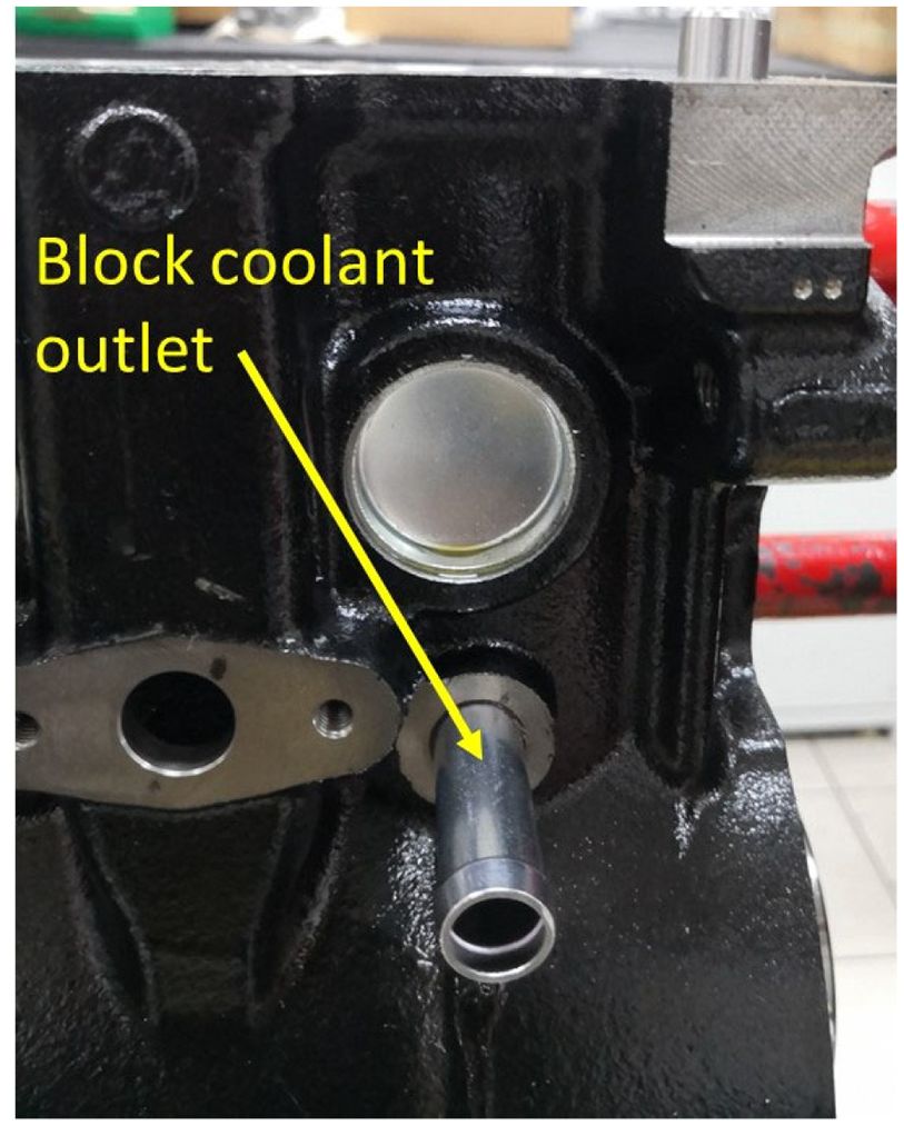
Demo1’s cylinder block with coolant outlet at the bottom of the water jacket’s rear end.
Combustion heat release happens mostly at the upper portion of the cylinder bore and the bore temperature plateaus below the top 40% of the piston stroke. 12 Caresana et al. 24 has also published the liner temperature profile showing big temperature reduction below the top 30% of the liner height. CFD plot by Qasemian and Keshavar 25 has shown that the flow velocity at the bottom portion of the cylinder block’s water jacket to be far lower than the velocity at the top portion of the water jacket. In this context, with the hot coolant at the upper portion of cylinder block’s water jacket eventually transferred to the cylinder head through the gasket apertures across the four cylinders, the cooler coolant along the bottom of the water jacket on the other hand will move from the first cylinder to the last without absorbing much of the heat from the cylinder bores. Swapping the coolant feed to the EHRU from the cylinder head to the cylinder block is likely to enable sooner and higher recoverable energy from the exhaust gas due to larger temperature difference between the EHRU and coolant.
From the commercial standpoint, there have been demands for the proposed thermal management system in the earlier studies11,12 to be applied to naturally aspirated engines which are still widely used by many motorcycles, small cars, and stationary engines. In 2018, the global sales of cars were 86 million 26 and 61.9 million for motorcycles. 27 In this context, any cost effective and practical fuel economy improvement technology that can be massively applied to these engines can effectively reduce the global energy usage more than the limited premium technologies applied to premium vehicles.
To sum it up, research gaps exist in terms of limited availability of high enthalpy exhaust gas in everyday driving, delayed availability of the recovered exhaust heat, complicated EHRU designs and constructions, high thermal inertia of the EHRUs and practicality of the EHRUs for mass applications to non-premium engines. On the other hand, opportunities exist in terms of the availability of sustainable source of cooler coolant from the cylinder block and high demands of cost effective naturally aspirated engines worldwide. In view of such opportunities, knowledge gaps exist on how to redesign the existing EHRUs and how it should work in order to exploit such opportunities to ultimately address all the highlighted research gaps.
In moving forward, a Proton Iriz 1.3 l with naturally aspirated engine was modified to include an EHRU made of a machined steel plate. If compared to the earlier studies,11,12 the EHRU was fed with cooler coolant from the cylinder block. Instrumentations wise, three flow meters were added to the circuit. Similarly, more thermocouples were added to measure the temperatures of the exhaust gas and the metal surfaces of the EHRU and its surroundings. The additions were crucial in establishing the various heat transfer modes during NEDC test. This study focuses on the improvements in warm-up time and recoverable thermal energy through the EHRU. Therefore, the test results and discussions covered the comparison of test vehicle with and without the EHRU.
Methodology
Cooling circuit and EHRU
Table 1 shows the vehicle specifications of the test vehicle with the proposed cooling circuit and EHRU. The engine and transmission electronics remained the same for all the tests conducted to focus solely on the mechanical changes without any influence of the electronics. Figure 3 shows the proposed cooling circuit with the EHRU located in between the cylinder block outlet and T-junction #2. The cooling circuit shares similarities with the cooling circuits used in the earlier studies11,12 except that the coolant passage in between the two T-junctions is not connected to any heat exchanger. Like the earlier studies, the coolant flows from T-junction #1 to #2 when the thermostat is fully close or partially open.11,12 By contrast, when the thermostat is wide or fully open, the coolant flow reverses direction by flowing from T-junction #2 to #1 and certain percentage of the coolant coming out of EHRU will be discharged to the radiator together with excess heat recovered from the EHRU. Using this partial flow diversion mechanism, the EHRU can be sized optimally to be enough in quickly providing heat during warm-up, idle, and part load driving without overheating the engine during full load driving.
Specification of the test vehicle.


(a) The proposed cooling circuit and the locations of the EHRU, thermocouples and flow meters and (b) cross section of the EHRU and locations of thermocouples adjacent to EHRU.
From the earlier studies, the relatively cooler coolant in the cylinder block was necessary to sustain the optimum temperature range of 70°–80°C for CVT oil instead of 100°–110°C for engine oil.11,12 Unlike the Demo1 test vehicle in the earlier study, 12 the cylinder block’s coolant outlet in this study is located 67 mm from the top deck and the piston stroke is only 73.4 mm. At this location, the outlet is located outside of the top 40% of the piston stroke.
The EHRU is made of 20 mm thick machined plate with drilled cooling channel inside it as shown in Figure 4. The long drilled passage connecting the other two drilled passages is plugged with taper plug at both ends of the passage. The coolant flows following the drilled passages as indicated by the blue arrows. Exhaust gas flows through the 53.8 mm machined hole surrounded by three M10 bolt holes. From Figure 5, the EHRU is placed in between the flanges of maniverter and the downpipe. Three-layer aluminum gasket (0.3 mm thick each) was sandwiched on each side of the EHRU to avoid gas leak and to enhance heat conductivity from the maniverter and downpipe to the EHRU.

(a) Diagram shows the bottom view of the EHRU with the cooling channel shown by the hidden lines. Locations of T14 and T18 are also shown in the diagram. The blue arrows show the direction of the coolant flow and (b) isometric view of the EHRU. The red arrow shows the direction of the exhaust gas.
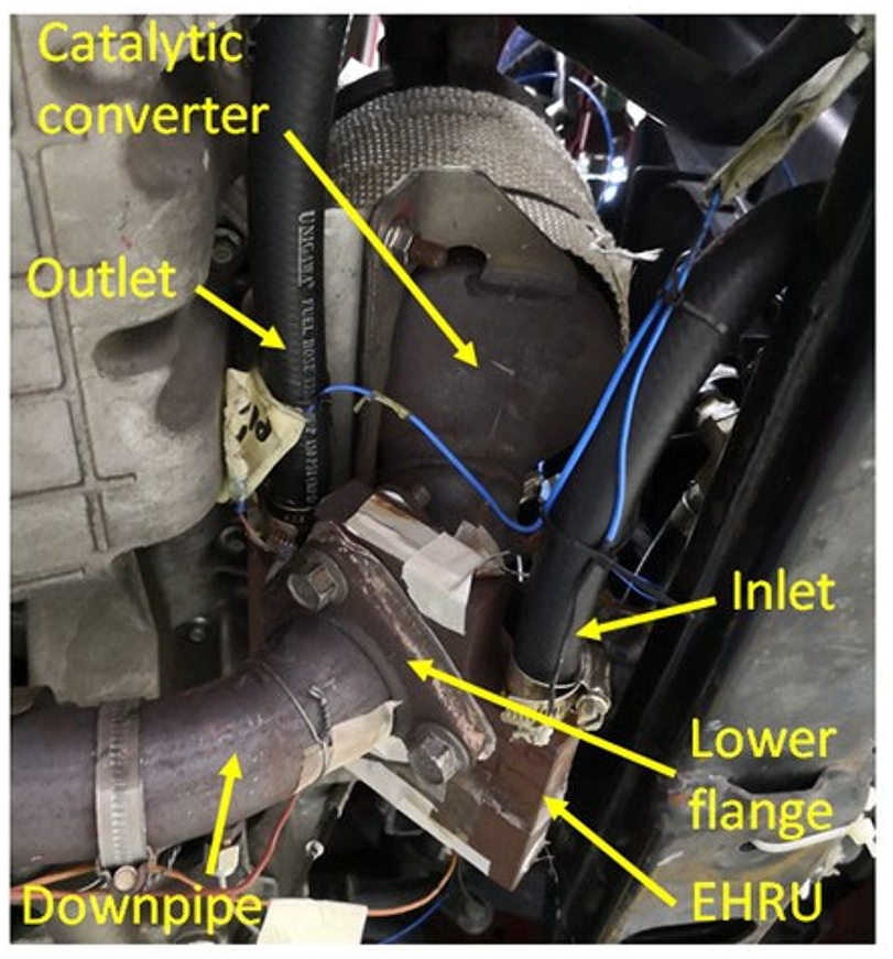
The location of the EHRU which is sandwiched in between the maniverter and downpipe.
Instrumentation of the test vehicle
Figure 3(a) shows the locations of thermocouple marked with capital letter “T” and flowmeter marked with capital letter “F.” The readings were recorded at 1 Hz in order to minimize fluctuations. Graphtec GL820 was used to record the information from the thermocouples and flow meters. INCA 7.1 with ETAS interface module was connected to the Bosch ECU to monitor the engine operating parameters especially the engine RPM and exhaust gas mass.
Compared to the earlier studies,11,12 more focus was given to the EHRU itself. In particular, two thermocouples were attached to the side walls of the EHRU as shown in Figure 4. Thermocouple T14 was placed on the “uncooled” side whereas the thermocouple T18 was placed on the “cooled” side adjacent to the coolant. The average temperature of the EHRU is stated in equation (1). Understanding that the metal temperature of the EHRU is not uniform throughout the engine operations, averaging these two points provides rough estimate of the EHRU’s average temperature.

As shown in Figure 3(b), another two thermocouples were attached to the upper flange (designated as T13) and lower flange (designated as T15). Prior to the attachment of the thermocouple, one layer of the thermal resistance tape was applied to the metal surface to insulate the thermocouple from the hot surface. This first layer of tape prevented the thermocouple insulator from melting while leaving the tip in contact with the metal surface. Once the position of the tip was fixed, another layer of tape was needed to cover the exposed tip and to secure the thermocouple assembly firmly on the surface. To measure the exhaust gas temperatures, two mounting points were welded to the upstream (designated as T16) and downstream (designated T17) exhaust pipes at roughly 50 mm from the upstream and downstream flanges as shown in Figures 3(b) and 6. The tip of the thermocouples protruded about 25–28 mm into the exhaust pipes to enable exhaust gas temperature at the center of the pipes to be measured.
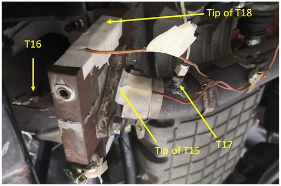
The position of the tip of the thermocouples around the EHRU.
As shown in Figure 3(a), three flow meters were installed strategically within the cooling circuit. F1 and F2 flow meters were placed at the proposed locations to enable coolant flow rates to be measured even when the coolant flowing along the T-junction #1 and #2 changes direction in accordance with the thermostat opening. Understanding that the flow meter works only in one direction, the addition or subtraction of F1 and F2 enables various coolant flow rates at various locations to be measured. The coolant flow rate coming out of the cylinder block (


Vehicle tests
Since the focus of the study here is to compare the effects of having the EHRU to the warm-up performances, the test vehicle was tested with and without the EHRU. For the tests without the EHRU, the EHRU was relocated from the exhaust system to the vehicle’s subframe. This ensured no heat transfer from the exhaust system and exhaust gas to the EHRU without causing cooling circuit pressure difference between the variants.
The tests involved the use of NEDC test as per earlier studies.11,12 Although the WLTP is more up-to-date and more relevant to automakers, NEDC was chosen in order to compare the test results with internal and publicly available test data. Furthermore, the clear separation between the UDC and EUDC phases enabled more focused data gathering of city and highway driving.
Although the earlier study has shown fuel consumption improvement as much as 4% during NEDC with improved warm-up performances, 11 the test vehicle this time was equipped with more modern production powertrain’s electronics requiring accurate modeling of important operating parameters specific to the homologation requirements. However, the test vehicle in this study has undergone major changes to the mechanical components if compared to the original production variant. Therefore, once the mechanical systems developments are completed, both the engine and transmission electronics need to be tediously recalibrated before the mechanical improvements in this study can be fully reflected into relevant improvements in the fuel consumption and emissions. In this context, extensive and time-consuming recalibrations are needed to revise the friction, cold start, and warm-up models within the control strategies for each of the test variants. Therefore, these recalibration activities were not part of the research scope. Nevertheless, once certain mechanical targets and milestone are met in the future, the recalibration activities can be outsourced to the calibration engineers at Proton. Considering that the expedited warm-up generally yielded fuel economy improvement ranging from 1.6% to 10.6%6,9,15,16,19, it was assumed that objective improvements in coolant, engine oil, and CVT oil warm-up would generally improve the fuel consumption during NEDC test.
Classical calculations
Heat transfer classical calculations
The various heat transfer to and from the EHRU can be summarized as per equation (4). The conduction heat transfers to EHRU are expected to be dominant throughout the engine operations.

The phenomena in the previous paragraph can be linked with


The exhaust gas gets hotter than the EHRU throughout the engine operations. Therefore, convection heat transfer as represented by equation (7) can be expected from the high velocity exhaust gas passing the EHRU’s 53.8 mm gas passage as shown earlier in Figure 4. The surface area (

Equation (8) represents the recoverable heat from the EHRU. In transporting out the recovered heat, the coolant coming in and out of the EHRU (

The EHRU becomes hotter very quickly than the ambient. Therefore, the heat losses to the ambient due to convection and radiation are represented by


Simplified energy system (SES)
From equations (5) and (6), the metal contacts and conduction heat transfers between the flanges to the EHRU are not perfect due to the existence of three-layer gasket on both sides of the EHRU. In quantifying the heat losses across the gasket, it is necessary for the temperature drop to be measured in between the layers. However, the high contact pressures in between the gaskets and flanges present challenges for thermocouples to be reliably placed there. Similarly, the uneven temperature distribution on EHRU’s surfaces due to multiple heat sources and cooling channel will further increase the errors.
From equation (7), the constant h in the equation changes rapidly 19 and it requires reasonably accurate Nusselt and therefore Reynolds and Prandtl numbers too. 29 Furthermore, the exhaust gas flow characteristics through catalyst brick and pipe bends before entering the EHRU can be unpredictable. In addition, the ongoing hydrocarbon oxidations before and after the catalyst and the rapidly changing engine speed and load throughout the engine operations affect the h constant. From equation (7), the average exhaust gas temperatures should be measured with reference to the temperatures at the inlet and outlet of the EHRU and not at the T16 and T17 thermocouples’ locations. Similarly, the surface temperature must be measured at the surface in contact with the exhaust gas. Unfortunately, placing thermocouples at these locations are also challenging. In circumventing the limitations, the EHRU and its surrounding can be simplified as confined by the phantom line shown in Figure 7. The system consists of the EHRU, truncated exhaust pipes upstream and downstream of the EHRU and flanges connected to the EHRU. The heat transfer to the system can be calculated using the equation (12).

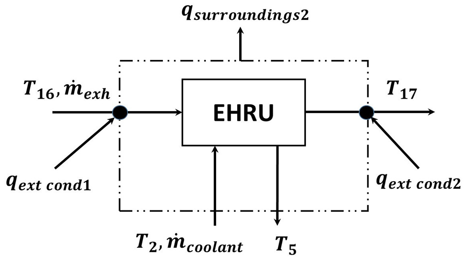
Simplified energy system (SES) to represent the EHRU and its heat sources.
In this case, the thermocouple T16 is the entry point and thermocouple T17 is the exit point of the system. The heat transfer or heat losses from the exhaust gas to the SES can be calculated using equation (13).


Results
NEDC test
From Figure 8, metal surfaces as measured by thermocouples T13, T14, and T15 are clearly hotter than the coolant exiting the cylinder block as measured by thermocouple T2. Even the thermocouple T18 which was located adjacent to the coolant passage of the EHRU is also hotter from t = 133 s (point a) onwards. By contrast, the coolant exiting the cylinder head measured by thermocouple T1 is hotter than the EHRU until t = 205 s (point b) of the test. Furthermore, the coolant temperature is also hotter than the lower flange (measured by thermocouple T15) from t = 49 s until t = 114 s.

Interactions between coolant and metals during the early part of NEDC test.
From Figure 9, the exhaust gas temperature difference between the upstream and downstream of the EHRU as measured by thermocouples T16 and T17 increases from t = 15 s for the variant with EHRU and t = 52 s for the variant without EHRU. The 37 s difference shows the significance of the EHRU in absorbing exhaust heat. Consequently, the coolant temperature difference between the inlet and outlet of EHRU steadily increases from the t = 25 s onwards indicating the initiation of the exhaust heat recovery and reuse that would eventually affect the warm-up process. As shown in Figure 10, the temperature difference between the coolant entering and exiting the EHRU somewhat stabilizes at around 3°C–4.2°C from t = 197 s until t = 1134 s. After this period, the number climbs up to 6.1°C especially when the EHRU and its surrounding were still hot, but the water pump speed dropped nearing the end of the test.
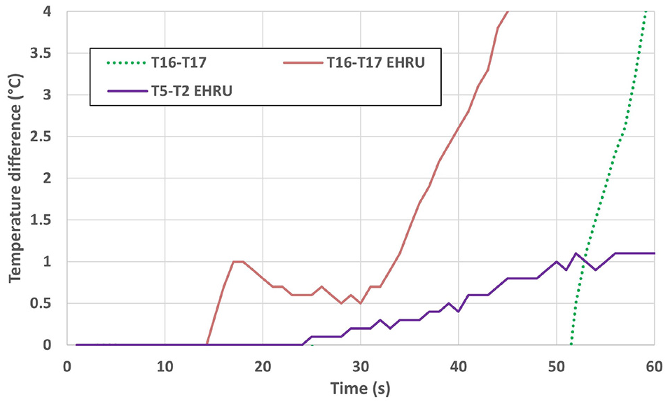
Chain of events that leads to the start of exhaust heat recovery and reuse.

Comparison of cylinder head coolant temperatures with and without the EHRU.
From Figure 10, the coolant exiting the cylinder head for the EHRU variant becomes hotter than the other variant from t = 58 s (point c ) onwards and this is 33 s after the exhaust heat recovery and reuse starts. Consequently, the thermostat opens earlier at the t = 714 s (point d) followed by t = 812 s (point e) for the non-EHRU variant.
Similarly, the coolant exiting the cylinder block (measured by thermocouple T2) becomes hotter but at higher rate as shown in Figure 11. In addition, the coolant entering the water pump (measured by thermocouple T12) is also hotter for the variant with EHRU. Interestingly, the coolant entering the water pump is hotter than the coolant exiting the cylinder block until the t = 187 s (point f) for the variant with EHRU compared to t = 380 s (point g) for variant without EHRU. The drop in temperature as the coolant exits the cylinder block indicated significant heat loss to the cylinder block.

Comparison of cylinder block coolant temperatures with and without the EHRU.
From Figure 12, the temperatures of the coolant entering and exiting the CVT oil cooler are higher for variant with EHRU. These relatively higher coolant temperatures increase the temperature difference between the coolant and CVT oil in the CVT oil cooler. In addition, the coolant temperature difference between the inlet and outlet is also higher than the variant without EHRU from t = 120 s onwards (point h) until the thermostat opens at t = 714 s. Both these phenomena improved the heat transfer to the CVT oil and its temperature increased at a much higher rate than the variant without EHRU as shown in Figure 13. The engine oil for variant with EHRU also has relatively higher temperature increase rate throughout most of the test duration.

Comparison of temperature increase at the CVT oil cooler during NEDC test for cooling circuit with and without the EHRU.

Comparison of temperature increase for CVT oil and engine oil during NEDC test.
From Figure 14, the exhaust gas temperatures measured by thermocouple T16 for both variants are not much different. However, the exhaust gas temperature measured by thermocouple T17 for the variant with EHRU is up to 55°C cooler meaning that the heat losses between the two thermocouples were higher. The difference once again shows the significance of the EHRU in absorbing heat from the exhaust gas within the SES. The exhaust gas temperature difference as measured by thermocouples T16 and T17 for the EHRU variant drastically dropped to below 15°C at t = 1057 s (point i). The sudden drop happened when the test vehicle was accelerating hard (point j) and the engine speed, load, and exhaust gas temperature were high. Similar drops can be seen elsewhere every time the test vehicle is undergoing hard acceleration. Interestingly, as the test vehicle decelerates (point k), the exhaust heat losses increases rapidly once again. Simultaneously as shown in Figure 15, the temperature of the upper flange (measured by thermocouple T13) rapidly drops although there is not much temperature change for the lower flange (measured by thermocouple T15). This indicated that the large heat transfer to the upper flange was no longer sustainable during the deceleration.
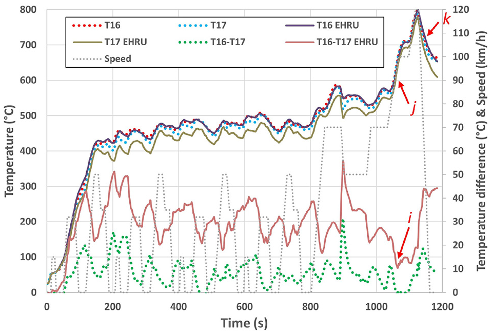
Comparison of temperature profiles for the exhaust gas during NEDC test.

Comparison of temperature increase for the exhaust system and EHRU during NEDC test.
From Figure 15, both the metal temperatures for upstream and downstream flanges for the EHRU variant increase rapidly from 200°C to 291.8°C and 140.2°C to 196.4°C, respectively from t = 1037 s until t = 1128 s. These rapid metal temperatures increase started 20 s earlier before the rapid drop in exhaust gas heat losses marked as point i in Figure 14. The delay suggested that as the metal temperatures of the flanges measured by thermocouples T13 and T15 increased above 210°C and 147.2°C, respectively, the hot metal surfaces within the SES were hot enough that the heat transfer from the exhaust gas was minimum. Although the measured temperatures are not accurately representing the surface temperatures in contact with the exhaust gas at temperature above 550°C, it can be assumed that the actual temperatures of the metal surfaces were far higher than the flanges’ temperatures.
From Figure 15, the variant without the EHRU has hotter upper and lower flanges if compared to the variant with EHRU. By contrast, the cooling effect of the EHRU has reduced the temperatures of the upper and lower flanges for the variant with EHRU. In addition, with the EHRU placed in between these flanges, the temperature difference between the upper and lower flanges is larger. The upper flange is much hotter than both the cooled and uncooled (measured by thermocouples T18 and T14 respectively) sides of EHRU. This suggested that there was a continuous heat transfer from the upper flange to the entire EHRU. The lower flange is also hotter than the cooled side of the EHRU throughout the test suggesting there was a continuous heat transfer from the lower flange to the cooled side of EHRU and the coolant flowing in the coolant passage. However, the graph also shows that the lower flange is only hotter than the uncooled side in the first half of the test. This indicated that the bulky uncooled side of the EHRU had thermal inertia high enough that it needed enough time for the temperature to be roughly equilibrium with the lower flange from t = 720 s (point l) onwards. Nevertheless, the lower flange’s temperature increases rapidly from t = 1050 s (point m) suggesting that the conduction heat transfer to the uncooled side of the EHRU happened once again during the high speed phase of the EUDC.
From Figure 16, the coolant exiting the cylinder head has the highest heat transfer of up to 6.4 kW. By contrast, the coolant exiting the cylinder block has the highest heat transfer of 2.14 kW. The CVT oil cooler has the highest heat transfer of 2 kW. From Figure 17, the maximum heat transferred out of the EHRU is 1.24 kW. By contrast, the maximum exhaust heat losses to the SES are lower at 1.06 kW. Interestingly, as the test vehicle enters the EUDC phase, the heat transferred from the coolant to the CVT oil drops from the t = 968 s (point p in Figure 16) due to the increase in CVT oil temperature from the transmission’s mechanical losses. The high mechanical losses during the 120 km/h drive caused the CVT oil cooler to switch its function by briefly cooling the CVT oil until the end of the 120 km/h drive. It once again supplied heat to the CVT oil when the test vehicle idled as it approached the end of the cycle.

Comparison of various heat transfers during NEDC test.

Comparison between exhaust heat losses and recovered exhaust heat from EHRU during NEDC test.
From Figure 17, the exhaust heat losses are generally higher than the heat transfer from the EHRU to the coolant during the UDC phase. However, the trend reverses during the EUDC phase. As shown in Figure 15, the temperatures of both the upper and lower flanges spike after point m resulting in large temperature differences between the flanges and the cooled side of the EHRU. These large temperature differences indicated large conduction heat transfers from the flanges to the EHRU that would eventually reach the coolant flowing inside the EHRU through convection heat transfer.
From Figure 18, the accumulated thermal energy profiles between the exhaust heat losses and EHRU confirmed that the thermal energy accumulated by the EHRU was lower than the exhaust heat losses during the UDC phase. However, as the test vehicle moved to the EUDC phase, both the exhaust heat losses and the heat transfer from the EHRU to the coolant increased simultaneously from point q but at different rates. In particular, the heat transfer from the EHRU to the coolant is higher as shown by the steeper curve. The two curves finally crossed at t = 1088 s (point r) and the gap widened afterwards. From Figure 18, as much as 998 kJ of thermal energy was discharged by the coolant to the CVT oil cooler. There was also thermal energy originated from the mechanical losses within the transmission assembly itself 24 but not included in this graph. Nevertheless, the CVT oil temperature was only 77°C at the end of the test and this suggested that the bulk of the thermal energy must have also been absorbed by the metals within the CVT assembly and some was also lost to the surroundings.

Comparison of various accumulated thermal energy transferred during NEDC test.
Summary of the warm-up performances
The warm-up performances of various fluids of both variants are summarized in Table 2. Improvements that are deemed to be significant have bold texts. From Table 2, the maximum temperatures of the cylinder head coolant for the cooling circuit with and without the EHRU are not much different. By contrast, the maximum temperatures of the cylinder block coolant are clearly higher for the EHRU variant. From Table 2, the cylinder head and cylinder block coolant of the EHRU variant reach 40°C and 60°C temperatures earlier. Similarly, its thermostat opens 98 s earlier.
Comparison of the warm-up performances involving various fluids during NEDC test.

As explained in the earlier studies, the thermostat opening does not rely directly on the hot coolant coming out of the cylinder head.11,12 Instead, it relies on the relatively cooler coolant after the CVT oil cooler and cabin heater as shown in Figure 3. In this context, even when the cylinder head coolant is more than 90°C, the thermostat will not open unless the coolant passing through thermostat is at least 76°C.
From Table 2, the improvements were decisive in which the CVT oil reaches the 40°C and 60°C temperatures much earlier for the EHRU variant. Nevertheless, the maximum CVT oil temperature is only 2.4°C higher than the variant without EHRU. From Table 2, the engine oil reaches the 40°C and 60°C temperatures significantly earlier for the EHRU. Similar like the CVT oil, the maximum temperatures of engine oil are only slightly higher for the EHRU.
Discussions
Connecting the dots
In the early part of NEDC tests as shown in Figures 8, the coolant from the cylinder block is continuously cooler than the entire EHRU and the rest of the metals within the SES. By contrast, the cylinder head coolant temperature increases rapidly and became hotter than the average temperature of the EHRU. By not feeding the cylinder head coolant through the EHRU, no heat was being wasted to heat up the cold EHRU during the early part of the tests. Instead, the cylinder head coolant was directed to the CVT oil cooler to expedite the CVT oil warm-up. By contrast, the coolant feed to the EHRU was much cooler as it came from the cylinder block. This arrangement rapidly increased the temperature gap between the coolant and the EHRU and eventually caused the coolant to exit the EHRU hotter.
The large temperature difference between the coolant exiting the cylinder head and cylinder block have similarities with the earlier studies.11,12 Nevertheless, the authors have not discussed in detail on how such distinctiveness was achieved. In this context, Figure 16 shows significant amount of coolant heat being absorbed by the lower portion of the cylinder bores across all four cylinders from the beginning until t = 187 s (range s). Considering that the combustion heat is mostly affecting the top 40% of the piston stroke, the cooler bottom portion of the cylinder bores have the tendency to absorb the heat from the relatively warmer coolant flowing through along the bottom of the water jacket. It was calculated that 17.5 kJ of thermal energy was absorbed within the stated time periods. Considering that there is plenty of engine oil splashes over the bottom portion of the cylinder bores and upper portion of the crankcase skirts from the rotating components,4,31,32 the absorbed coolant heat contributed to heat up the engine oil. The large thermal inertia from both the engine oil and metals ensured continuous coolant heat absorption. This explains why it took a few minutes before the coolant exiting the cylinder block would have the same temperature as the coolant entering the water pump as shown in Figure 11.
As shown in Figure 9, significant exhaust heat losses were detected by thermocouples T16 and T17 as early as t = 15 s but the coolant temperature difference of the EHRU started only at t = 25 s. This delay was likely to be caused by the thermal inertia from the combined exhaust pipes, flanges, connectors and EHRU within the SES. Considering that the EHRU is only 1.6 kg and the delay was a matter of 10 s, such delay could have been longer in case heavier EHRU was used. Heavier EHRU like the one used by Faurecia weighs 5.4 kg 5 and the big void inside it requires a lot of coolant to fill the gap. Although the large surface area of the heat transfer fins is highly effective in transferring the exhaust heat to the coolant, both the coolant and metals have high specific heat capacities. In this context, recovered exhaust heat extracted from the Faurecia’s EHRU was only available after 50 s of the cold start. 5 As a reference, Vittorini et al. 8 repeatedly mentioned about their exhaust-to-oil heat recovery unit requiring at least 200 s before heat recovery process could take place. The authors also briefly discussed about reducing the delay down to 120 s but achieving it would induce higher exhaust backpressure from the increased heat transfer surface areas.
From Table 2 and Figures 10 to 13, the presence of the EHRU has significantly improved warm-up performances for the coolant, engine oil, and CVT oil. The clear improvement in cylinder block coolant warm-up is desirable in quickly heating the engine oil on the bore surface and to thermally expand the bottom portion of the cylinder bores to achieve optimal bore-to-piston clearance for efficient piston reversal process. The improvement in cylinder head coolant warm-up was relatively smaller at the beginning but significant enough to minimize the intake port wall wetting. The increase in coolant temperature at the later stage was likely to benefit in minimizing the combustion gas quenching. Similarly, such increase heated up the engine oil inside the oil jacket above the cylinder head’s water jacket. The increase in engine oil temperature as shown in Figure 13 was significant and with no oil cooler installed, the relatively higher engine oil temperature was caused by the increase in cylinder block’s and cylinder head’s coolant temperatures.
From the practicality standpoint, the proposed EHRU was purposely designed to speed up the recovered exhaust heat availability as the main priority. Considering that heat exchangers in general have slow response due to the mass and size.20,21 the proposed EHRU is lightweight and compact to lower the thermal inertia. Despite its effectiveness in minimizing the delay, the minimum surface area for heat transfer to take place has limited the amount of recoverable heat. Nevertheless, it was still able to recover and reuse 346 kJ of thermal energy and as much as 1.24 kW of post catalyst low-grade heat which would otherwise be wasted during the NEDC test. Throughout the test, as much as 114.7 kJ of thermal energy was recovered and reused by the time thermostat opened at t = 714 s. This added energy has significantly improved the warm-up performances as shown in Table 2.
In case the test vehicle equipped with the EHRU is pushed at higher engine speed and load than the highest engine speed and load experienced during NEDC, the limited surface area also limits the amount of recoverable heat in which it will not be far higher than 1.24 kW. In this context, the hard driving is likely to open the thermostat wide and more than half of the recovered heat will be directed from T-junction #2 to T-junction #1 and eventually to the radiator instead of being wholly recirculated into the engine. This mechanism prevents overheating without the need to adopt the pneumatic flap to divert the exhaust gas 5 or to enlarge the radiator size.
As shown in Figure 19, the efficiency of the EHRU is at its lowest at point u. From equation (14), such low efficiency happens when the temperature difference between the upstream and downstream exhaust gas temperature as measured by thermocouples T16 and T17 is small. Interestingly, even when the efficiency is low at point u, the heat transfer from the EHRU to the cooling circuit as shown in Figure 16 is still higher than the exhaust heat losses between the two measured points. In this context, the rapid increase in flanges’ metal temperatures during the EUDC phase in Figure 14 suggested considerable conduction heat transfers from the upstream and downstream of the SES moving toward the EHRU.

Efficiency of the EHRU during NEDC.
From Figure 19, the average and maximum efficiency of the EHRU throughout the NEDC are 7.2% and 16.5%, respectively. By contrast, Faurecia’s EHRU has 85% average efficiency. 5 Such low efficiency is a big trade-off to primarily achieve low thermal inertia crucial for better response. In addition, the trade-off positively addresses the complexity, high exhaust backpressure, size, weight, and overheating at high load operations that generally come with conventional EHRUs.
Key findings, novelties, and new knowledge established in the study
Taking just 25 s after the cold start for the coolant exiting the EHRU to become hotter is a reasonable benchmark for researchers looking for ways to speed up the warm-up process under the bigger picture of lowering the fuel consumption, greenhouse gases, and tailpipe emissions. In particular, the very rapid exhaust heat recovery process can be beneficial for everyday driving which requires frequent stopping, idling, short driving distance, and for engines with the engine start-stop technology. The availability of recovered exhaust heat is much faster than any other known EHRU technologies that are based either on thermoelectric, Rankine cycle or even the ones currently in production intended to speed up the powertrain warm-up process. This highly responsive mechanism enables rapid, effective, efficient, and sustainable exhaust heat recovery applicable even to future gasoline and diesel engines with low overall exhaust gas temperature.
The study has also proven that low enthalpy and low exergy exhaust gas energy can be recovered and reused. Considering that the recovered sensible heat used directly and exhaustively to heat up the fluids and metals, there was no concern in terms of energy conversion losses and entropy formation which may exist in thermoelectric and Rankine cycle based EHRUs. The additional energy rapidly added to the coolant from the EHRU was significant and can be reused for many measures that can improve the fuel economy.
Unlike other EHRUs, the proposed EHRU is made of simple, cost effective, reliable, and durable heat exchanger plate that relies on conduction heat transfers from its hotter metal surroundings. Instead of integrating the EHRU with heat transfer fins to increase the heat transfer surface areas, the proposed EHRU uniquely relies on its metal surroundings that have large surface areas in contact with exhaust gas across both the upstream and downstream of the EHRU. Doing so avoids the proposed EHRU from becoming complicated, delicate, heavy, bulky, and costly. Consequently, the combined thermal inertia of both the metals and excess coolant within the EHRU is minimal and this is another key enabler in speeding up the recovered heat availability.
Even though many conventional EHRUs rely on the convective heat transfer from the exhaust gas to the heat transfer fins, this study has also revealed the significance of the conduction heat transfer making its way to the EHRU and eventually to the coolant flowing in it through convection heat transfer. Even if the conventional EHRUs are equipped with pneumatic flap to divert the exhaust gas away from the heat transfer fins, there will still be significant conduction heat transfer making its way to the metals adjacent to the cooling passage at high engine load. By contrast, the unavoidable conduction heat transfer was anticipated at the beginning of the study and the circuit was uniquely designed to divert more than half of recovered exhaust heat to the radiator when the thermostat is wide or fully open. This measure minimizes the recovered heat from being recirculated into the engine and it minimizes the risk of engine overheating at high load operations.
In general, other EHRUs have high exhaust backpressure due to the use of highly restrictive heat transfer fins. Furthermore, the use of more restrictive after treatments to meet the future tailpipe emissions regulations when combined with these restrictive EHRUs may negatively affect the maximum specific outputs of these engines. By contrast, the proposed EHRU as shown in Figure 4 exerted no significant increase in exhaust backpressure. As a result, no engine electronics recalibrations were required during the early part of the development because no significant drivability or cycle-to-cycle variations were detected during idle, low, and medium load driving. This opens the possibility for the proposed EHRU to be retrofitted to the existing engines currently in use. Furthermore, with no known restriction to the exhaust flow, there was no fouling or stain on the metal surfaces in contact with the exhaust gas as pointed out by Jouhara et al. 33 even after big mileage accumulation.
Future works
The cheaper and simpler production variant of the EHRU is currently being designed and will be made from cast iron instead of machined steel block. In particular, the main body where the flanges are connected will have its thickness reduced from 20 mm to 6–8 mm. This thin section is closely surrounded by relatively thicker sections to house cast water jacket for the coolant to flow in and out. The cast water jacket provides meandering water passage uniformly close to the mating faces for better heat transfer and more uniform temperature distribution. The production EHRU is expected to be below 1 kg and this will likely lower the thermal inertia further to speed up the recovered heat availability.
Ferrous metals like iron and steel do not have thermal conductivity as high as aluminum, magnesium, copper, and even brass. Understanding that the EHRU is tightly sandwiched rather than hanging or supporting other structures, it is possible to use these metals provided that the mating faces do not deform over time. The effectiveness of these metals can be simulated or even tested in the future.
The proposed cooling circuit and the coolant feed arrangement to the EHRU are applicable to turbocharger based EHRU in the earlier studies.11,12 Even though the thermal inertia is bigger due to the part weight of more than 5 kg, the start of the heat recovery and reuse is expected to be much earlier than the 170–180 s after cold start as per what reported. 11 Such potential and the growing number of downsized turbocharged engines in passenger cars can guarantee good future for the proposed technology.
Conclusions
From the NEDC test, the combination of the simplified split cooling with the proposed EHRU has successfully improved the warm-up performances of coolant (across the cylinder block and cylinder head), CVT oil and engine oil. Throughout the NEDC test, the average and maximum EHRU efficiency were 7.2% and 16.5%, respectively. Nevertheless, the EHRU supplied 346 kJ of thermal energy and as much as 1.24 kW of heat to the cooling circuit of the 1.3 l naturally aspirated SI engine. Throughout the test, as much as 114.7 kJ of thermal energy was supplied by the time the thermostat opened at t = 714 s and the amount was significant enough to make the difference in warm-up performances.
The EHRU was also able to recover and reuse the exhaust heat as early as t = 25 s. The early addition of the recovered thermal energy to the cooling circuit was also significant in improving the warm-up performances. Such short period is uncommon from other EHRU technologies and this makes it a perfect candidate to address the real-world driving conditions consist of frequent stop, idle, part load and short distance driving. In particular, the proposed EHRU is a must have item for growing number of hybrid and non-hybrid cars using engine start stop technology.
The key knowledge in achieving these feats was in feeding the EHRU with cooler coolant feed from the bottom of the cylinder block water jacket’s rear end without compromising the heat buildup at the upper and middle portions of the cylinder bores. The continuous coolant flow along the bottom of the water jacket to the outlet was also beneficial in exhausting the remaining precious heat to warm-up the bottom portion of the cylinder bores and the splashed engine oil prior to the recirculation of the coolant to the EHRU in the early phase of the cold start.
From the design standpoint, the proposed EHRU uniquely relies on conduction heat transfers from other metal parts connected to it. In the absence of heat transfer fins to maximize heat transfer, the proposed EHRU relies on the surface areas of the parts connected to it. This makes it light, compact, simple, durable, cost effective and with no increase in exhaust backpressure. The 1.6 kg EHRU has low thermal inertia and this expedites the recovered heat availability. By conducting further research in this area, the proposed EHRU design can be evolved further and may become a new trend for EHRUs in the future.
In getting the EHRU closer to production, design activities are now ongoing to replace the drilled coolant passage with cast water passage. Such water jacket brings the coolant uniformly closer to the heat sources for potentially double-digit percentage heat transfer improvement over the current design. This latest design reduces the weight below 1 kg to further reduce the thermal inertia highlighted in the study. Considering that the EHRU has no elevated mechanical loading requirements, there is also an option to use metals with better thermal conductivity like brass, aluminum and copper.
From the energy conservation perspective, the cost effective EHRU is intended for massive and quick applications to electric generators, motorcycles and small segment passenger cars in which cost effective naturally aspirated engines are still being widely used globally. Without doubt, this is where the focus should be. Understanding that the fuel economy is expected to improve when the coolant, oils and metals are quickly and sustainably kept at the optimum operating temperatures in real world driving, the combined energy savings worldwide from mass applications of the proposed EHRU are much higher than what achievable by the more premium fuel saving technologies applied to premium cars.
Footnotes
Appendix
Handling Editor: James Baldwin
Declaration of conflicting interests
The author(s) declared no potential conflicts of interest with respect to the research, authorship, and/or publication of this article.
Funding
The author(s) disclosed receipt of the following financial support for the research, authorship, and/or publication of this article: This research was internally funded by Perusahaan Otomobil Nasional Sdn Bhd (Proton) without involving any external funding.