
Abstract
Wall thinning, as one of the key defects in tube bending determined the forming quality and limit, is more easily to occur due to the specific properties of high strength 0Cr21Ni6Mn9N stainless steel tube (0Cr21Ni6Mn9N-HS tube). To achieve tube accuracy numerical control (NC) bending forming, the wall thinning characteristics of the 0Cr21Ni6Mn9N-HS tube should be clarified. An analytical model was proposed to reveal the essential relation between tube parameters and wall thickness distribution. Considering the varied elastic modulus, a finite element (FE) model was applied to explore the wall thinning under different geometrical and process parameters. Using the modified multi-parameter sensitivity analysis method combined with FE simulation, the sensitivity of the wall thinning to geometrical and process parameters was carried out. The experiments of NC tube bending were conducted to validate the analytical and simulate results. The results show that the varied elastic modulus can enhance the wall thinning degree, but has no obvious effect on wall thinning characteristics. The wall thinning characteristics under different geometrical and process parameters are revealed and the reasonable parameters ranges for the 0Cr21Ni6Mn9N-HS tube in NC bending are obtained. The most sensitive parameter on wall thinning is the relative bending radius, while the bending angle is the least one.
Introduction
Metallic tube and tubular parts play a crucial part in many key industrial fields as “bleeding” transforming because of their special characteristic of hollow structure and excellent whole performance. 1 The high strength 0Cr21Ni6Mn9N stainless steel tube (0Cr21Ni6Mn9N-HS tube) has attracted increasing applications in aviation, aerospace, shipbuilding, and so on owing to the advantages of high strength, excellent corrosion resistance, and perfect high temperature oxidation resistance. 2 However, compared with Al-alloy tube and common stainless steel tube, the 0Cr21Ni6Mn9N-HS tube is more prone to wall thinning, cross section deformation and springback defects in numerical control (NC) bending due to the specific properties of the 0Cr21Ni6Mn9N-HS tube such as the large yield strength, poor plasticity, and high ratio of yield strength to elastic modulus. The elastic modulus virtually changes with increasing the plastic strain and it is a crucial mechanical property parameter that influences the plastic forming quality. The wall thinning, as one of the key defects in tube bending determined the forming quality and limit, should be strictly controlled to meet aviation standard. Therefore, to obtain reasonable bending forming parameters, the wall thinning behaviors of the 0Cr21Ni6Mn9N-HS tube in NC bending considering the variation of elastic modulus under different forming conditions should be clarified. The results are of great theoretical significance and practical application value to achieve the tube precision NC bending forming.
In recent years, great efforts have been carried out on the wall thinning of tube bending using analytical, experimental and numerical methods. Tang 3 derived the analytical formula for wall thickness change in tube bending based on the theory of plastic deformation and geometrical characteristics of tube bending. Wang and Agarwal 4 developed an analytical model to predict wall thickness variation of tube bending under axial force and internal pressure by using plasticity theories. E et al. 5 deduced approximate equation for wall thickness change in tube bending according to in-plane strain assumption and exponential hardening law. On the basis of the geometrical characteristics of tube bending and plastic deformation theory, the theoretical model of wall thinning for thin-walled tube bending was established by Li et al. 6 Using the plastic deformation theory, Lu et al. 7 presented several analytical formulae with respect to stress, neutral layer deviation, wall thickness variation and cross section distortion to explore the phenomena of tube bending. Although a large number of assumptions and simplifications are set in the derivation process of the theoretical model, it can build an essential relation between bending deformation and tube parameters including mechanical properties and geometrical parameters.
By experimental method, Oliveira et al. 8 investigated the effect of lubricant conditions on wall thickness variation and surface quality in mandrel-rotary draw bending of steel and aluminum alloy tube. Wu et al. 9 experimentally studied the influences of temperature, bending speed and original grain size on the bendability of wrought magnesium alloy AM30 tubes and found that the middling temperature, small bending speed and original grain size were conducive to decrease the wall thinning degree. Li et al. 10 researched the influences of process parameters on wall thinning and cross section distortion of large diameter thin-walled 5052O aluminum alloy tubes by the NC hydraulic tube bender. The results show that the influences of process parameters on large diameter thin-walled Al-alloy tubes are similar to those on small diameter thin-walled tubes, but the wall thinning of large diameter thin-walled tube in NC bending is more sensitive to process parameters. The influences of dies on wall thickness variation of thin-walled rectangular 3A21 Al-alloy tube during NC bending were experimentally investigated in literature. 11 Safdarian and Kord 12 experimentally studied the influences of the pressure of pressure die and mandrel parameters such as mandrel diameter and mandrel position on wall thinning and cross section deformation of BS3059 steel tube during NC bending according to orthogonal experiment scheme, and they obtained the optimal parameters for NC bending of the BS3059 steel tube.
By finite element (FE) numerical simulation method, Fang et al. 13 addressed the effects of geometrical parameters on wall thickness variation and cross section distortion of high strength TA18 tube during NC bending. Guo et al. 14 numerically explored the influences of additional axial tension on wall thickness change of 0Cr18Ni9 stainless steel tube during equal curvature-diameter bending without mandrel. Jeong et al. 15 numerically investigated the effects of bending radius on wall thickness variation and ovality of Inconel 625 fine tube with the size of 1.5 mm×0.12 mm (outer diameter×wall thickness) during bending process. The effects of different push assistant loading conditions on wall thinning, cross section distortion, and wrinkling behaviors of thin-walled aluminum alloy and stainless steel tube during NC bending were studied based on ABAQUS code by Li et al. 16 Using FE analysis, Zhan et al. 17 researched the wall thinning and cross section distortion of medium strength TA18 tube in NC bending under different die sets. Recently, for the 0Cr21Ni6Mn9N-HS tube bending, Fang et al. 18 established a three dimensional (3D) elastic plastic FE model of the 0Cr21Ni6Mn9N-HS tube in NC bending and explored the influences of friction conditions 19 and mandrel parameters 20 on wall thinning and cross section distortion.
However, in the above FE modeling process, the elastic modulus was regarded as a constant. In the circumstances, especially for the 0Cr21Ni6Mn9N-HS tube with high ratio of yield strength to elastic modulus, the simulation results will produce a great deviation from the experimental results to some extent. Thus, in this work, the analytical models are presented to reveal the essential relation between tube parameters and stress/strain distributions as well as wall thickness distributions. Considering the variation of elastic modulus, the 3D elastic plastic FE model of the 0Cr21Ni6Mn9N-HS tube in NC bending is established. Using the FE model, the wall thinning characteristics under different geometrical and process parameters are explored and the reasonable bending forming parameters are obtained. Using the modified multi-parameter sensitivity analysis method combined with FE simulation, the sensitivity of geometrical and process parameters on the wall thinning is obtained. The results can provide the theorical reference and practical application value for choosing reasonable geometrical and process parameters during tube precise NC bending forming.
Forming principle and index of tube NC bending
For tube NC bending process, the rotary draw bending is used, as shown in Figure 1. The bending die, clamp die and pressure die are three basic die sets for achieving tube bending. The tube is first clamped to the bending die by clamp die, and the pressure die is set on outer side of the tube to provide enough pressure force and bending moment to the tube, then the bending die and clamp die revolve together with the bending speed ω, the pressure die moves forward (forward moving speed Vp is called push assistant speed of pressure die) to push the materials into bending deformation regions, and the tube is dragged past the bending tangent point and revolves along the bending die groove to form gradually into the desired bending radius R and bending angle ψ. After that, the dies are removed, and the tube is unloaded. Moreover, for the process with harsh bending conditions and small tolerance, the bending process must be equipped with mandrel and wiper die to lower the cross section deformation and wrinkling risk of the tube. Especially the mandrel extension length e plays a crucial role in that.
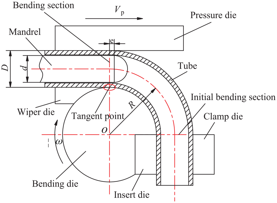
Schematic diagram of tube NC bending.
The wall thinning is inevitable for the outside wall of the tube after bending, and its significantly influences the strength and flow capacity of the bent tube. The wall thinning degree can be referred to as the index to evaluate the bending forming quality and forming limit of the tube. The larger the index is, the worse the forming quality is. In view of high-pressure hydraulic system safety requirement of aircrafts, the wall thinning degree should be less 15%. The wall thinning degree

Where

Bent tube cross-section.
Analytical model of wall thickness distribution in tube bending
Tube bending is a multi-factor coupling effect complicated physical process. The following assumptions are proposed to deduce the prediction models with respect to the wall thickness distribution, stress/strain distribution for tube bending:
(1) The tube is continuous, isotropic elastioplastic material that satisfies the Mises yield criterion, and the Ludwigson model is used to describe the strain hardening behaviors. The stress-strain relationship can be obtained as:

Where
The variation of elastic modulus with plastic deformation is supposed to be a function of plastic strain during tube bending process, which can be written as:

Where E0 is the initial elastic modulus, Ec is the elastic modulus for current moment, which can be expressed as 21 :

Where Es is the stable value of elastic modulus,
(2) The shear stress

(3) The tube material is incompressible during bending process and Bauchinger effects are neglected.
(4) The lagged effect of strain is negligible, and the neutral layer of strain is consistent with that of stress during tube bending process.
(5) The flattening in tube bending process is ignored and the arbitrary cross section of tube keeps plane before and after bending.
(6) The friction of the tube versus dies is ignored in tube bending.
(7) The inner radius of the tube r is presumed to be unchanged due to the rigid support of mandrel.
According to the generalized Hooke’s law and assumption (2), the stress-strain relation in the elastic deformation region can be expressed as equation (6).

Where
In accordance with equations (5) and (6), the tangent stress-strain relationship in the elastic deformation region can be obtianed as:

According to the Hencky total strain theory including elastic strain and assumption (2), the stress-strain relationship in the plastic deformation region can be written as:

Where
Based on equations (5) and (8), the relationship between hoop stress and tangent stress can be gotten as:

According to the volume invariant condition and equation (5), the equation (10) for the tangent strain versus the normal strain can be obtained as:

According to the assumption (2), when the shear stress and shear strain are neglected in elastoplastic tube bending process, the equivalent stress, and equivalent strain can be expressed as:
Where
In accordance with equations (9)–(12), the equivalent stress and equivalent strain can be obtained as equations (13) and (14), respectively.

On the basis of equations (2), (13), and (14), the tangent stress-strain relation in the plastic deformation region can be obtained as:

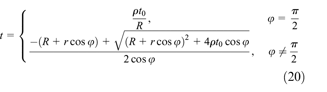
According to the assumption (4) and the results of E et al., 22 the neutral layer curvature radius ρ can be obtained by equation (16).

Where R is the bending radius, D is the outer diameter of the tube and δ is the reduction of the tube diameter after bending, which is experimentally obtained as 10%
The normal strain and tangent strain of the bent tube cross-section can be written as equations (17) and (18) considering the neutral layer variation.


Where m is the distance from the measure position to geometrical neutral layer, which can be determined by equation (19).

Where φ is the position angle of the tube cross-section as shown in Figure 2.
By substituting equations (17)–(19) into equation (10), the tube wall thickness after bending can be derived as:
According to equations (14) and (18), the tangent strain at the junction of the elastic deformation region and the plastic deformation region for the outer side tube section can be expressed as equation (21) due to the occurrence of material yielding.

Where
From equation (21), the x1 can be deduced as:

According to the geometrical characteristic in Figure 2, equation (23) can be gotten.

Where
In accordance with equation (20),

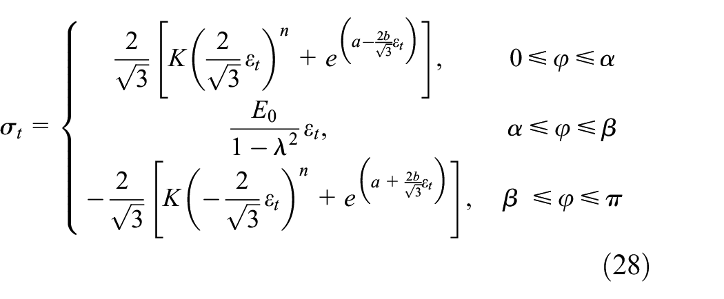
By substituting equations (22) and (24) into equation (23), α can be obtained as:

By using the same steps that deduced the distance x1 and the angle α, the distance x2 and the angle β shown in Figure 2 can be obtained as equations (26) and (27), respectively.

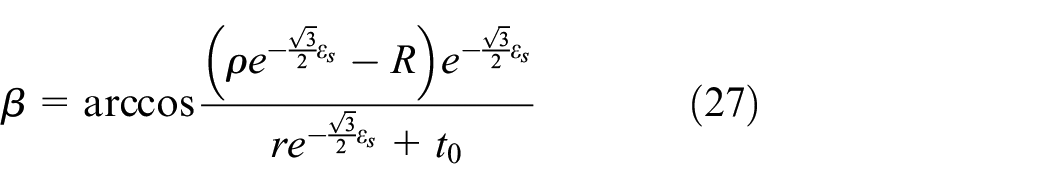
According to equations (7), (15), (25), and (27), the tangent stress on the bent tube cross-section can be written as:
3D-FE model considering variation of elastic modulus
Taking 9.53 mm × 0.51 mm tube specification as an object, a 3D-FE model was established on the platform of ABAQUS for the NC bending of the 0Cr21Ni6Mn9N-HS tube with the bending radius of 3D, as shown in Figure 3. The explicit algorithm was employed for bending tube and retracting mandrel simulation, while the implicit one was used for unloading springback calculation.

3D-FE model of the 0Cr21Ni6Mn9N-HS tube during NC bending.
The basic mechanical properties of the 0Cr21Ni6Mn9N-HS tube were obtained by uniaxial tensile test, as shown in Table 1. The relationship between elastic modulus and plastic strain of the 0Cr21Ni6Mn9N-HS tube was obtained by repeated loading-unloading tensile test according to the Chinese standard GB/T228.1-2010,
23
as shown in Figure 4. The strain hardening behaviors were described by Ludwigson model
Mechanical properties of the 0Cr21Ni6Mn9N-HS tube.


Variation of elastic modulus with plastic strain of the 0Cr21Ni6Mn9N-HS tube.
The tube was discretized by four-node doubly curved thin shell element S4R, while four-node bilinear quadrilateral rigid element R3D4 was applied to mesh the rigid dies. The meshing sizes 1.0 mm × 1.0 mm and 1.5 mm × 1.5 mm were used for the tube and die surfaces, respectively. The mass scaling factor 3000 was obtained by convergence analysis to equilibrate the numerical precision and stability. Five integration points with Simpson integration rule were employed across the wall thickness of the tube.
The “displacement/rotation” and “velocity/angular” were applied to achieve the practical tube NC bending. The smooth step amplitude curves were employed for defining the smooth loading of all dies except for wiper die to reduce inertial effects in explicit simulation of the quasi-static process. The coulomb friction model was used for describing the friction behaviors for tube versus dies, and the corresponding friction coefficients in various contact interfaces were listed in Table 2. For unloading process, all dies were removed and an encastre boundary was applied to avoid rigid movement.
Friction coefficients in various contact interfaces.
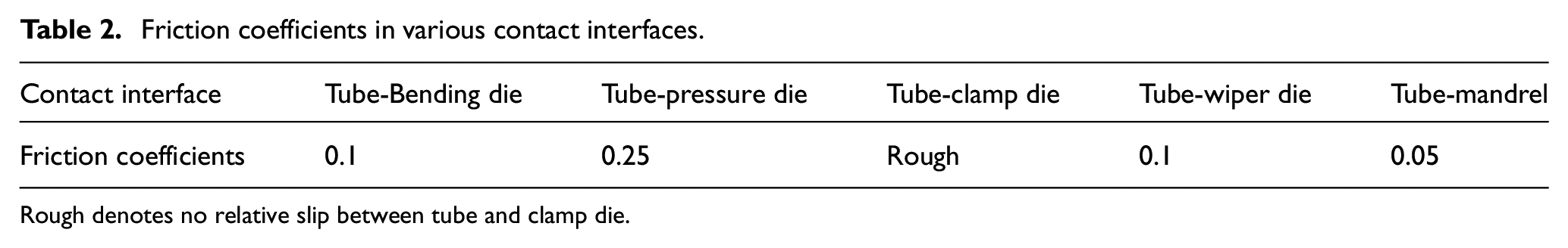
Rough denotes no relative slip between tube and clamp die.
Results and discussion
Evaluation of theoretical and FE models
Figure 5 shows the comparison between theoretical/simulated results and experimental results of the 0Cr21Ni6Mn9N-HS tube in NC bending with the bent tube specification of 9.53 mm × 0.51 mm×28.59 mm (tube diameter×wall thickness×bending radius) and the bending angle of 180°. The bending conditions were listed in Tables 2 and 3. The wall thickness of tube was measured by using a micrometer screw gauge. As observed in Figure 5(a), the change trend of the wall thickness distributions at mid-cross section for the analytical results is similar to that of the experimental results, and the analytical results of wall thickness distributions are close to the experimental ones with the maximum relative error of 6.4%. For the wall thinning degree, the analytical results keep constant along the whole bending process with the increase of the bending angles, as shown in Figure 5(b). This is because that the analytical model of wall thickness distributions has nothing to do with the bending angle. The analytical wall thinning degree are larger than the experimental ones. The discrepancy is originated from the assumptions in section 3. Namely, the friction and flattening during tube bending are ignored. However, the relative error of the maximum wall thinning degree between the analytical wall thinning degree and experimental one is still smaller, only 17.44%. Therefore, by equation (20), the theoretical model for wall thickness distributions is dependable, which can be used for quickly predicting the wall thickness variation during tube bending.
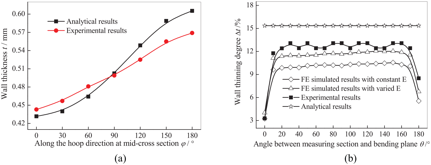
Comparison between theoretical/simulated and experimental results: (a) wall thickness and (b) wall thinning degree.
Other bending conditions for the 0Cr21Ni6Mn9N-HS tube in NC bending.

From Figure 5(b), it can be found that the simulated results considering the varied elastic modulus are closer to the experimental ones. The relative errors of the maximum wall thinning degree with and without considering the varied elastic modulus are 7.72% and 19.27%, respectively. This means that the simulated precision of the wall thinning degree can be improved by 11.55% when considering the variation of elastic modulus. This is related to the varied elastic modulus in tube bending process. The amount of the elastic modulus changes with the increase of the plastic deformation, and the nonuniform distribution of the elastic modulus causes the tube capable to acquire precise stress and strain. The tangential tensile stress considering the varied elastic modulus is larger than that when ignoring the elastic modulus variation. 21 Since the wall thinning in tube bending is caused by the tangential tensile stress, increasing the tangential tensile stress will help to improve the simulated precision of the wall thinning degree. Thus, the FE model considering the variation of elastic modulus can precisely describe the tube bending deformation and can further address the wall thinning characteristics of the 0Cr21Ni6Mn9N-HS tube in NC bending under different geometrical and process parameters.
Wall thinning characteristics under different geometrical parameters
Figure 6 shows the wall thinning degree of the 0Cr21Ni6Mn9N-HS tube in NC bending under different bending angles ψ with varied and constant E. As observed in Figure 6, the change tendencies of the wall thinning degree are similar for both cases from the bending section to the initial bending section, but the wall thinning degree increases when considering the varied E.
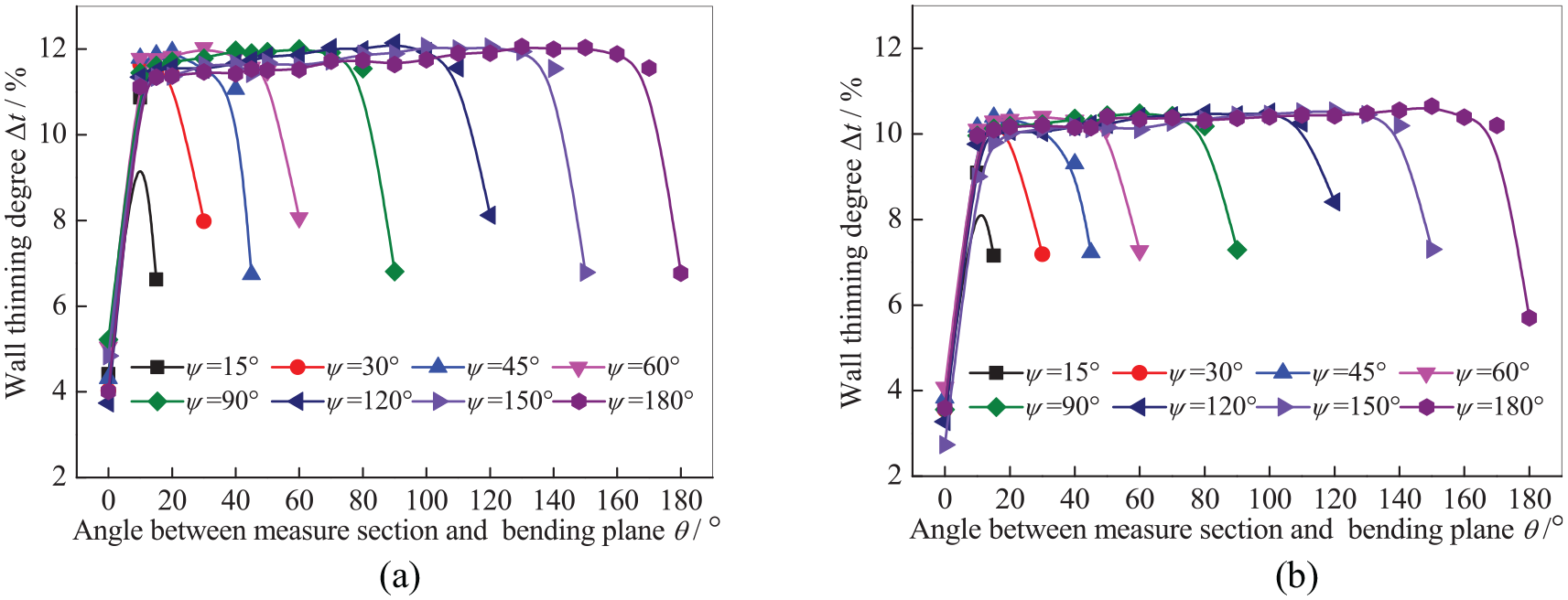
Wall thinning degree at different bending angles ψ: (a) with varied E and (b) with constant E.
When the bending angle is less than 30°, the wall thinning degree augments at first and then reduces from the bending section to the initial bending section, and the maximum wall thinning degree augments inch by inch with the increase of the bending angle. When the bending angle is more than 30°, the wall thinning degree enters stable platform deformation features. And with increasing the bending angle, the platform height is almost unchanged, only its length augments. The results are similar to the wall thinning degree of the high strength TA18 tubes in NC bending, 13 but are different from the wall thinning degree of the Al-alloy thin-walled tubes in NC bending. 24 The main reasons are that the 0Cr21Ni6Mn9N-HS tube will gradually enter a stable bending stage with the progress of the bending process until the contact, friction, and interaction for tube versus dies reach a steady state and the work hardening of the tube reaches a certain degree when the bending angle exceeds 30°, which make the wall thinning degree no longer increase and present a stable platform expansion phenomenon.
Figure 7 shows the wall thinning degree of the 0Cr21Ni6Mn9N-HS tube in NC bending under different relative bending radii R/D with varied and constant E. From Figure 7, it is found that the change tendencies of the wall thinning degree are similar for both cases from the bending section to the initial bending section, but the wall thinning degree increases when considering the varied E.

Wall thinning degree at different relative bending radii R/D: (a) with varied E and (b) with constant E.
For a specific relative bending radius, the wall thinning degree augments at the beginning, then scarcely varies, and reduces in the end from the bending section to the initial bending section. The wall thinning degree augments with the decrease of the relative bending radius, indicating that the small relative bending radius will increase the risk of thinning even crack of the tube. This is because that the bending deformation degree augments with the decrease of the relative bending radius, which makes the wall thinning degree increase. When the relative bending radius is equal to 2.0 in both cases, the wall thinning degrees are 16.71% and 15.92%, respectively, which exceed the maximum limit 15% of the aviation standard. Under the circumstances, the outside wall thickness of the tube may have cracked. Thus, to obtain the qualified bent-tube components, the relative bending radius of the 0Cr21Ni6Mn9N-HS tube during NC bending must be more than 2.0.
Wall thinning characteristics under different process parameters
Figure 8 shows the wall thinning degree of the 0Cr21Ni6Mn9N-HS tube in NC bending under different clearances of tube-mandrel Cm with varied and constant E. It can be seen from Figure 8 that the change tendencies of the wall thinning degree are similar for two conditions from the bending section to the initial bending section, but the wall thinning degree increases when considering the varied E.

Wall thinning degree at different Cm: (a) with varied E and (b) with constant E.
For a given clearance Cm, the wall thinning degree also increases sharply in the vicinity of the bending plane and decreases abruptly near the initial bending plane, while its hardly changes in the middle section, namely, a platform deformation features occur with the angle θ from 20° to 160°. When the clearance Cm increases, the wall thinning degree decreases correspondingly. This is because that increasing the clearance between tube and mandrel makes the friction force of the mandrel on the tube reduce, which causes the tangential tensile stress to decrease. Thus, the wall thinning degree decreases with the increase of the clearance Cm. Moreover, too small clearance of tube-mandrel is easy to aggravate die wear and scratch the surface of the tube, which will affect the service life of the die and the surface quality of the tube. While excessive clearance of that will cause the risk of wrinkling and severe cross section distortion. Therefore, the suitable clearance between tube and mandrel should be 0.075–0.15 mm.
Figure 9 shows the wall thinning degree of the 0Cr21Ni6Mn9N-HS tube in NC bending under different clearances of tube-pressure die Cp with varied and constant E. It can be found from Figure 9 that the change tendencies of the wall thinning degree are similar under two conditions from the bending section to the initial bending section, but the wall thinning degree increases when considering the variation of the E.

Wall thinning degree at different Cp: (a) with varied E and (b) with constant E.
When the clearance between tube and pressure die increases, the wall thinning degree augments correspondingly, especially when the clearance increases from 0.075 to 0.1 mm. While when the clearance continues to augment, the wall thinning degree augments indistinctively, especially for the constant E. This is because that increasing the clearance of tube-pressure die makes the friction force of the pressure die on the tube reduce. Namely, the push assistant role of the pressure die on the tube is weakened, and the material supply for the bending deformation zoon is reduced correspondingly, which causes the wall thinning degree to augment. When the clearance Cp is more than 0.1 mm, the friction force of the pressure die on the tube reduces seldom. So, the wall thinning degree increases little relative to that varies when the Cp increases from 0.075 to 0.1 mm. Meanwhile, the tube is prone to produce vibration in bending process with the larger clearance Cp, which affects the bent tube forming quality. Therefore, the suitable clearance between tube and pressure die should be 0.075–0.1 mm.
Figure 10 shows the wall thinning degree of the 0Cr21Ni6Mn9N-HS tube in NC bending under different friction coefficients of tube-mandrel fm with varied and constant E. It is found that the change tendencies of the wall thinning degree are similar for both cases from the bending section to the initial bending section, but the wall thinning degree increases when considering the variation of the E.

Wall thinning degree at different fm: (a) with varied E and (b) with constant E.
With the increase of the friction coefficient fm, the wall thinning degree augments, but the increase degree is not significant. This is because that increasing the friction coefficient fm makes the friction force of the mandrel on the tube augment, viz., the drag force exerted by tube-mandrel friction augments, which blocks the tube material to flow forward and causes the wall thinning degree to increase at the extrados. Meanwhile, the larger friction coefficient of the fm will make the contact condition of tube-clamp die vary from static state to kinetic one. The occurrence of the relative slip of tube-clamp die will cause the bending deformation to be unstable and increase the risk of wrinkling near clamp die. 25 Therefore, the friction coefficient of tube-mandrel should be as small as possible. The reasonable friction coefficient of the fm in this interface should be 0.05–0.15, and enough lubricant should be uniformly applied to the inside tube and mandrel surface.
Figure 11 shows the wall thinning degree of the 0Cr21Ni6Mn9N-HS tube in NC bending under different friction coefficients of tube-pressure die fp with varied and constant E. It can be seen from that the change tendencies of the wall thinning degree are similar for both cases from the bending section to the initial bending section, but the wall thinning degree increases with considering the varied E.

Wall thinning degree at different fp: (a) with varied E and (b) with constant E.
When the friction coefficient fp increases from 0.05 to 0.5, the wall thinning degree reduces, but the reducing degree is not obvious. The main reason is that increasing friction coefficient fp can exert more push assistant role of the pressure die, viz., the larger the friction coefficient is, the more push assistant role of the pressure die is. In other words, the material in straight section of the tube is easier to push into the bending deformation zoon with the large friction coefficient, which makes the tangential tensile stress on the outside of the tube decrease correspondingly. Therefore, the wall thinning degree reduces. Due to the features of the sliding friction, the contact area for the tube-pressure die increasingly reduces with increasing the bending deformation degree, so the friction force of the pressure die on the tube augments non-significantly with the increase of the friction coefficient fp. Moreover, the larger friction coefficient fp is prone to cause the tube outside surface to be abraded, which affects the usability performance of the tube. Thus, the suitable friction coefficient ranges of the fp should be 0.25–0.4, and the dry friction condition can meet the requirements of the steady bending without abrading tube outside surface.
Figure 12 shows the wall thinning degree of the 0Cr21Ni6Mn9N-HS tube in NC bending under different mandrel extension lengths e with varied and constant E. It is discovered from that the change tendencies of the wall thinning degree are similar for both cases from the bending section to the initial bending section, but the wall thinning degree increases when considering the variation of the E.

Wall thinning degree at different e: (a) with varied E and (b) with constant E.
With increasing the mandrel extension length, the wall thinning degree increases. The main reason is the support role of the front end of mandrel on the outside of the bending section of the tube. The larger the mandrel extension length is, the more the support zone is, which makes the material flow restrain vastly. Therefore, it is difficult for the material to flow from the straight section to the bending section, which will cause the outside wall thickness of the tube to decrease. When the mandrel extension length equals 2.5 mm, the curve of the wall thinning degree fluctuates in the middle part. This is related to the overlarge mandrel extension length. Overlarge mandrel extension length will produce the phenomena of convex hull, overthinning, or even cracking, which cause the wall thinning degree to fluctuate. The maximum mandrel extension length emax 2.2 mm is calculated by a formula
Sensitivity analysis of geometrical and process parameters on wall thinning degree
On the foundation of study on the effects of geometrical and process parameters on wall thinning degree of the 0Cr21Ni6Mn9N-HS tube during NC bending, using the modified multi-parameter sensitivity analysis model, as shown in equation (29), 27 the sensitivity values Sk (ak) of different parameters including the ψ, R/D, Cm, Cp, fm, fp, and e on the maximum wall thinning degree Δtmax are calculated as shown in Table 4. The Sk (ak) (k = 1, 2, …, v) are a set of dimensionless non-negative real number, and the greater the Sk (ak) is, the more sensitive the wall thinning degree to this parameter is. For the sensitivity analysis of wall thinning degree of the 0Cr21Ni6Mn9N-HS tube in NC bending, the system features P = f (ak) refer to the maximum wall thinning degree Δtmax, and the influence factors ak refer to geometrical and process parameters.

Where u is the number of the
Sensitivity values of different parameters.

To get a more intuitive analysis, the sensitivity values for different parameters in Table 4 are further drawn by the column figure, as shown in Figure 13. It can be seen from that the most sensitive parameter for the wall thinning degree of the 0Cr21Ni6Mn9N-HS tube during NC bending is the relative bending radius R/D, the next are the clearance of tube-mandrel Cm, mandrel extension length e, clearance of tube-pressure die Cp, friction coefficient of tube-pressure die fp and friction coefficient of tube-mandrel fm, while the bending angle ψ is the least sensitive parameter for the wall thinning degree.

Sensitivity of different parameters on wall thinning degree.
Conclusions
In this study, the analytical models for the stress/strain distribution, wall thickness distribution of the tube bending were proposed. Considering the variation of elastic modulus, the 3D-FE model of the 0Cr21Ni6Mn9N-HS tube during NC bending was established, and the wall thinning characteristics under different geometrical and process parameters were revealed. The main conclusions are as follows:
The analytical results of the wall thickness distribution are close to the experimental results with the maximum relative error of 6.4%, which can be used to quickly predict the wall thickness distribution of tube bending.
The wall thinning characteristics of the 0Cr21Ni6Mn9N-HS tube in NC bending are similar with or without considering the variation of elastic modulus under different geometrical and process parameters, but only increases the value of the wall thinning degree when considering the varied elastic modulus.
The wall thinning degree firstly increases sharply, then hardly changes, and finally decreases abruptly from the bending plane to the initial bending plane and increases with the increase of the Cp, the fm and the e or with the decrease of the R/D, the Cm, and the fp, while it first increases, then hardly changes with the increase of the ψ.
The suitable parameters ranges for the 0Cr21Ni6Mn9N-HS tube in NC bending are as follows: the ψ up to 180°, the R/D >2.0, the Cm of 0.075–0.15 mm, the Cp of 0.075–0.1 mm, the fm of 0.05–0.15, the fp of 0.25–0.4 and the e of 0–2 mm.
The sensitive parameters on wall thinning degree from high to low are the R/D, the Cm, the e, the Cp, the fp, the fm and the ψ.
Footnotes
Handling Editor: James Baldwin
Declaration of conflicting interests
The author(s) declared no potential conflicts of interest with respect to the research, authorship, and/or publication of this article.
Funding
The author(s) disclosed receipt of the following financial support for the research, authorship, and/or publication of this article: This work was supported by the Natural Science Foundation of Jiangxi Province [grant number 20192BAB216022]; the Research Project of Science and Technology of Jiangxi Provincial Department of Education [grant number GJJ180615, GJJ201126]; and the National Defense Key Discipline Laboratory of Light Alloy Processing Science and Technology, Nanchang Hangkong University [grant number gf201501001].