
Abstract
This study adopts the DMT(dynamic mesh technology) and UDF(user defined functions) co-simulation method to study the dynamic characteristics of aerostatic thrust bearings with equalizing grooves and compare with the bearing without equalizing groove under high speed or ultra high speed for the first time. The effects of air film thicness, supply pressure, rotation speed, perturbation amplitude, perturbation frequency, and cross section of the groove on performance characteristics of aerostatic thrust bearing are thoroughly investigated. The results show that the dynamic stiffiness and damping coefficient of the bearing with triangular or trapezoidal groove have obvious advantages by comparing with that of the bearing without groove or with rectangular groove for the most range of air film thickness, supply pressure, rotation speed, perturbation amplitude, especially in the case of high frequency, which may be due to the superposition of secondary throttling effect and air compressible effect. While the growth range of dynamic stiffness decreases in the case of high or ultra-high rotation speed, which may be because the Bernoulli effect started to appear. The perturbation amplitude only has little influence on the dynamic characteristic when it is small, but with the increase of perturbation amplitude, the influence becomes more obvious and complex, especially for downsized aerostatic bearing.
Keywords
Introduction
Aerostatic bearings are one of the most important parts of precise and ultra-precise machinery, which are widely used in aerospace, biomedicine, high-precision machine tools and measuring instruments. The aerostatic bearings have the advantages of high precision, low friction and no pollution, but at the same time, due to the compressibility of the air film, they have low stiffness, and low bearing capacity in steady operation, moreover, the low stability under micro-perturbation when subject to dynamic perturbation forces. The traditional evaluation of aerostatic bearing is mostly based on the static characteristics or the dynamic characteristics of stationary state and without pressure equalizing groove. However, with the rapid development of ultra-precision and ultra-high-speed machines, the research on the dynamic characteristics of aerostatic bearing under high speed or ultra high speed becomes more and more significant in the evaluation of its working performance.
Accordingly, some researchers have studied the dynamic characteristics. The dynamic stiffness is much more sensitive to the perturbation frequency rather than the nanoscale perturbation amplitude by simulations and experiments. 1 The static and dynamic characteristics of aerostatic bearings with numerous small feed holes less than 0.05 mm diameter by using the finite difference method and reported that a higher maximum stiffness could be obtained by reducing the diameter of feed holes and the damping coefficient increased remarkably with decreasing bearing clearance but was insensitive to the number of feed holes. 2 Chen et al. 3 theoretically analyzed the nonlinear frequency dependence of these dynamic characteristics which is due to compressibility of the air. The difference of dynamic coefficients between coupled and uncoupled perturbation Reynolds equation is more prominent when the perturbation frequency ratio and rotating speed increase by solving the coupled perturbation Reynolds equation. 4 Deb 5 reported that stiffness and damping characteristics provide the limitations of stability for the bearing which lead to the instability and critical frequency which are obtained along with inertia number. A comparison between a bearing with orifices and bearings either with a groove or made from porous material is carried out using frequency response measurements. The results show that the bearing with orifices is better damped than the other types for the highest load capacity. 6 Pneumatic hammer instability tends to occur at low perturbation frequencies at small orifice diameters (<0.25 mm), large gap heights (>20 µm) and large supply pressures. 7 Nishio et al. 8 confirmed that aerostatic thrust bearings with small feedholes could have larger stiffness and damping coefficient than bearings with compound restrictors. In order to suppress the micro-perturbation, the air supply pressure should be kept as small as possible, while the small air pocket diameter and orifice diameter are also needed. 9 The impulse response fluctuation amplitudes of the X-shaped grooved aerostatic bearing decreases with groove widths and depths. 10 Cui et al. 11 presented that the stiffness and stability of aerostatic circular pad bearings are influenced significantly by geometrical and material parameters. The depths of the circumferential PEGs (pressure-equalizing grooves) have great impacts on the load performance. Compared with opening the circumferential PEGs, opening the axial PEGs is more helpful to improve the load capacity, even opening only one or two axial PEGs 12 and the dynamic stiffness increases with the increase of frequency, and the equivalent damping coefficient decreases with the increase of frequency. 13 Belforte et al. 14 reported that the load carrying capacity and the stiffness of the aerostatic thrust bearing with groove increases significantly, especially at low gas film thickness, where the air flow only has a slight increase. Maamari et al. 15 proposed an orifice based aerostatic bearing with a compliant back plate to improve performance, the reaults show that an increase by a factor of three in stiffness compared to conventional bearing while ensuring a positive damping. Qiao et al. 16 concluded that the trapezoidal section has the maximum static bearing capacity and static stiffness, while air consumption rate of unit load is the lowest. The adoption of the pressure-equalizing grooves can substantially improve the load capacity and static stiffness of the bearing and make the bearing maintain a uniform stress, which enhances operating accuracy and life of the bearing 17 and the effects of prous bearing and the form of resitrictor on the change law of dynamic stiffness and damping coefficient. 18 Chen et al. 19 revealed from the simulations that a better static performance can be obtained based o the proper value of axial groove length. The method combining traditional engineering simplification algorithm and CFD can analyze the static and dynamic perfrmances of the complex structure bearing with high accuracy and low time cost. 20
In conclusion, there is almost no research work that has been done on the dynamic characteristics aerostatic thrust bearing with pressure equalizing groove at high-speed and ultra high speed state. Therefore, to address the gap in the literature, the steady-state Reynolds equation and perturbation Reynolds equation are obtained, based on linear perturbation method for aerostatic thrust bearing, the perturbation Reynolds equations are solved to obtain the dynamic stiffness and damping coefficient of the aerostatic thrust bearing. CFD simulation models are built up to investigate the dynamic characteristics of the aerostatic thrust bearing with pressure equalizing groove at high speed or ultra-high speed state. The effects of air film thickness, supply pressure, perturbation frequency, perturbation amplitude, rotation speed, and cross section of the groove on the dynamic characteristics of the aerostatic thrust bearings with pressure equalizing groove are analyzed in this research.
Aerostatic thrust bearing with/without annular pressure equalizing groove
The illustration of aerostatic thrust bearing with pressure equalizing groove is shown in Figure 1(a). There are four orifice restrictors distributing uniformly in circumference of the bearing, cylindrical, air chamber exists at the outlet of each restrictor. The aerostatic bearing without pressure equalizing groove has exactly the same dimensions as the bearing with pressure equalizing groove. The cross section shape of the thrust bearing are shown in Figure 1(b), B and C represent enlarged views of the restrictor and equalizing groove respectively. The three different sections of annular pressure equalizing grooves are illustrated in Figure 1

A: Aerostatic thrust bearings studied in this research: (a) bearing with annular pressure equalizing groove and (b) cross section shape of the bearing. B: enlarged view of the restrictor.
Principal dimensions of aerostatic thrust bearings.

Numerical model
Governing equations
The Reynolds equations for aerostatic thrust bearing are obtained based on the following assumptions:
Since the gas film thickness is much smaller than the length and width of the gas film, the gas pressure along the gas film thickness direction is a constant.
The airflow is isothermal in the aerostatic thrust bearings.
The air viscosity in the bearing gas film is sticky degree of constant.
(d) Based on the above assumptions, the Reynolds equation can be deduced as:
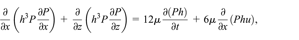
where
In the case of small perturbation of the aerostatic bearing, the pressure perturbation equation and the film thickness perturbation equation are respectively expressed as equation (2) and equation (3):


where 0 and 1 represent the steady state and perturbation state respectively,
Combining the above-mentioned equations, steady state Reynolds equation is obtained as:

and perturbation Reynolds equation is given by:

The film thickness


where
From the equations (6) and (7), the following formulas are derived:


Substituting the equations (6)–(9) into the perturbation Reynolds equation and combining the steady state Reynolds equation to calculate


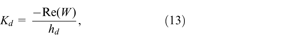
Hence, the dynamic stiffness

Boundary conditions and mesh model
The dynamic characteristics of the aerostatic thrust bearing is numerically studied by adopting the CFD software ANSYS-Fluent which adopts the combination of modified fluid mechanics formulas and experimental models, the whole flow process of complex airflow field can be simulated accurately. It is vital to solve the pressure distribution of aerostatic bearing with groove structure under high speed and ultra high speed. Due to the periodic and boundary conditions of the 3D air flow model, one fourth of the air flow field is considered in the computations to reduce the cost. The boundary conditions of the 3D air flow model with pressure equalizing groove are depicted in Figure 2, pressure inlet and pressure outlet are specified at the orifice supply, the inner and outter peripheries of the bearing respectively. Periodic and adiabatic boundary conditions are prescribed at the periodic walls, rotation wall is the boundary condition of rotation speed. The rest other walls of the 3D air flow model are assumed to be adiabatic, stationary and rigid walls. For the analysis of dynamic characteristics, a sinusoidal boundary condition is applied to the rotation and perturbation wall by user-defined-functions, and the dynamic mesh modeling approach will be employed in this study. The 3D air flow model with pressure equalizing groove, illustrated in Figure 2, takes the same boundary conditions as the bearing without pressure-equalizing groove. The grid model divided by ICEM CFD is shown in Figure 3.

The computational model with pressure equalizing groove and boundary conditions.

The grid model with pressure equalizing groove.
Verification of model
The accuracy of the DMT and UDF co-simulation method needs to be verified. Therefore, the dynamic stiffness and dynamic damping of the aerostatic thrust bearing with orifice restrictor are analyzed to prove the accuracy of the DMT and UDF co-simulation method. The basic dimensions and operating parameters of the verification bearing are shown in Table 2. Bsed on the prncipal parameters, the coparison between the co-simulation method and reported work are carried out which are showen in Figure 4, it can be observed that both dynamic stiffness and dynamic damping of the simulation are very close to the resported results, which verify the accuracy of the DMT and UDF co-simulation method.
Principal parameters of verification bearing and operation.


Verification of model: (a) comparative dynamic stiffness between the reported work and simulation and (b) comparative dynamic damping between the reported work and simulation.
Numerical simulation
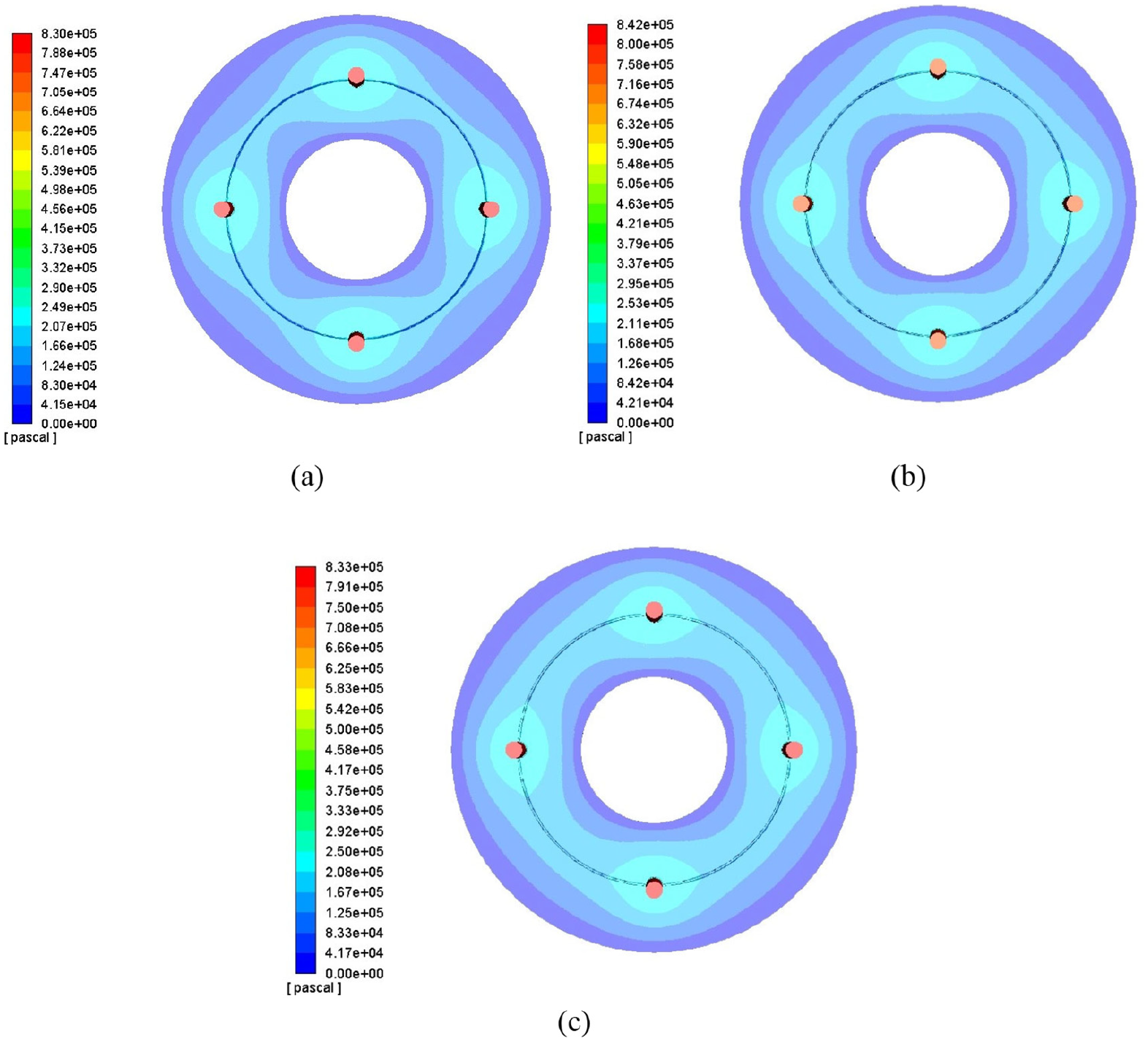
Figure 5 shows the total pressure disturbation vary with rotation time of the bearing with triangular pressure equalizing groove at film thickness 12

The pressure distribution of the bearing with the triangular groove in a period time: (a) t = 0 or T/2, (b) t = T/4, and (c) t = 3T/4.
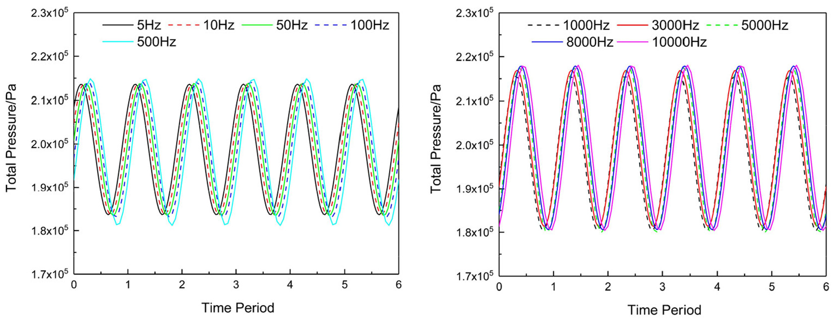
The total pressure at different perturbation frequency under 150,000 r/min.
Figure 7 shows the total pressure disturbation of the bearing with different types of grooves at film thickness 12
The pressure distribution of the bearing with different types of grooves: (a) rectangular groove, (b) trapezoidal groove, and (c) triangular groove.

The total pressure of the bearing with different types of grooves at time period.
Simulation results and discussions
The influence of film thickness
The simulation results about the influence of the air film thickness on the dynamic stiffness and damping coefficient for the aerostatic thrust bearing with or without groove at air supply pressure 0.6 MPa, rotation speed 20,000 r/min, and perturbation amplitude 0.4

Dynamic stiffness under different gas film thickness: (a) dynamic stiffness at h = 8 µm, (b) dynamic stiffness at h = 12 µm, (c) dynamic stiffness at h = 16 µm, and (d) dynamic stiffness at h = 20 µm.
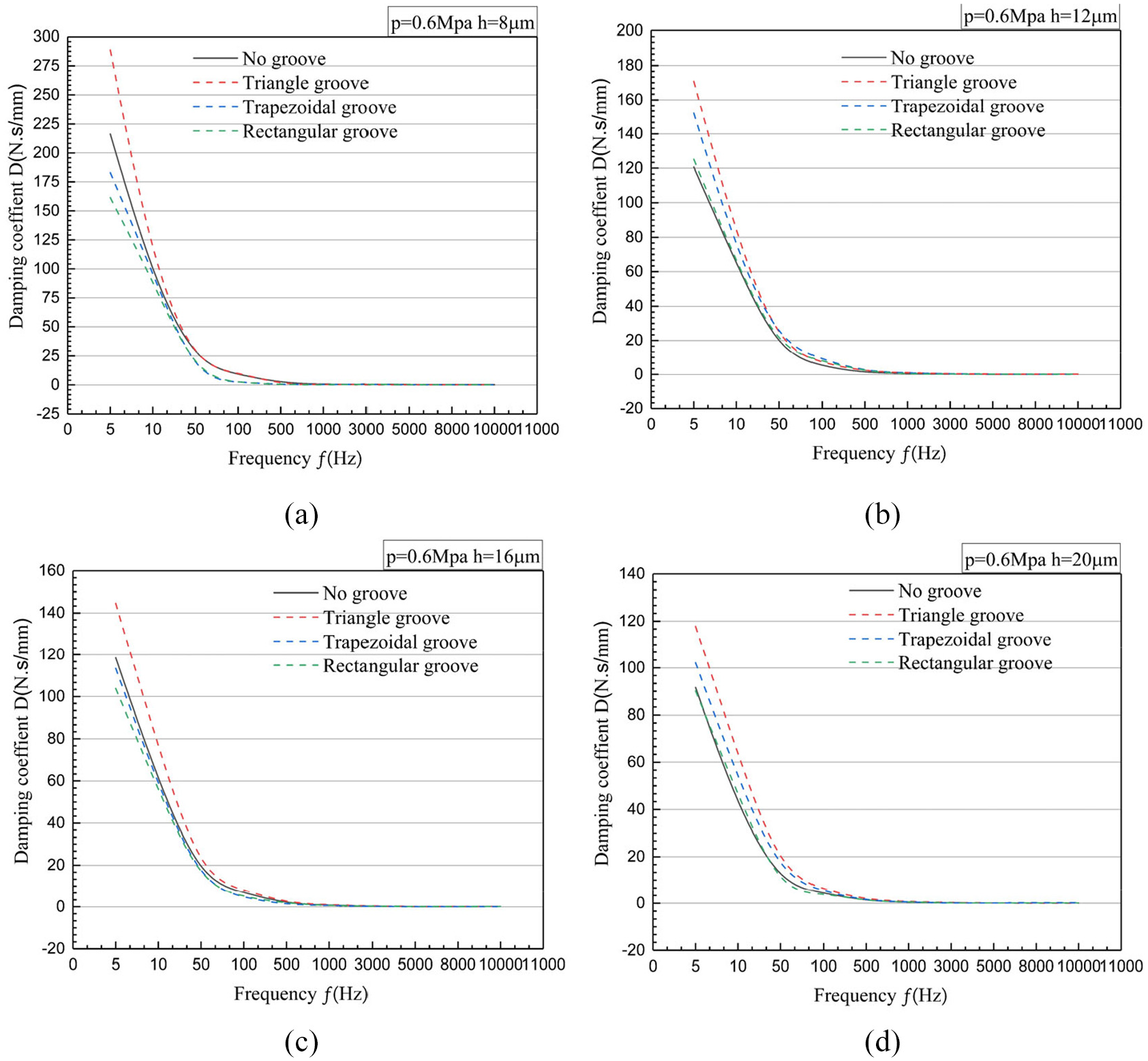
Damping coefficient under different gas film thickness: (a) damping coefficient at h = 8 µm, (b) damping coefficient at h = 12 µm, (c) damping coefficient at h = 16 µm, and (d) damping coefficient at h = 20 µm.
The influence of supply pressure
The influence of the supply pressure on the dynamic stiffness and damping coefficient for the aerostatic thrust bearing with or without groove are studied at the gas film thickness 12 µm, rotation speed 20,000 r/min and perturbation amplitude 0.4

Dynamic stiffness under different supply pressure: (a) dynamic stiffness at P = 0.4 MPa, (b) dynamic stiffness at P = 0.8 MPa, and (c) dynamic stiffness at P = 1 MPa.

Damping coefficient under different supply pressure: (a) damping coefficient at P = 0.4 MPa, (b) damping coefficient at P = 0.8 MPa, and (c) damping coefficient at P = 1 MPa.
The influence of rotation speed
The influence of the rotation speed on the dynamic stiffness and damping coefficient for the aerostatic thrust bearings with or without groove are investigated at the gas film thickness 12

Dynamic stiffness under different rotation speed: (a) dynamic stiffness u = 100,000 r/min, (b) dynamic stiffness at u = 150,000 r/min, and (c) dynamic stiffness at u = 200,000 r/min.

Damping coefficient under different rotation speed: (a) damping coefficient at u = 100,000 r/min, (b) damping coefficient at u = 150,000 r/min, and (c) damping coefficient at u = 200,000 r/min.
The influence of perturbation amplitude
The influence of the perturbation amplitude on the dynamic stiffness and damping coefficient are shown in Figures 15 and 16, four different amplitudes of 0.2, 0.3, 0.4, and 0.5

Dynamic stiffness under different perturbation amplitude: (a) dynamic stiffness at

Damping coefficient under different perturbation amplitude: (a) damping coefficient at
Conclusions
In this paper, the dynamic characteristics of aerostatic bearing with different cross-section pressure equalizing groove and the bearing without pressure equalizing groove at high speed and ultra-high speed are studied for the first time by means of DMT of CFD and UDF. The effects of the section shape of the pressure equalizing groove, perturbation amplitude, film thickness, perturbation frequency, supply pressure, and rotation speed on the dynamic characteristics of aerostatic thrust bearing are studied. Several conclusions can be drawn from this study which are listed below:
The DMT and UDF can be combined to solve the transient fluid dynamics equations and to study the dynamic characteristics of aerostatic bearing with micro-groove structure at high speed or ultra-high speed, which is extremely difficult to study under experimental conditions.
The variation law of dynamic stiffness is complex. In this study, the dynamic stiffness of the aerostatic bearing increases with the increase of frequency when only one of the conditions is changed, such as s air film thickness, supply pressure, perturbation amplitude, groove section shape, perturbation frequency and rotation speed, except when the gas film thickness is changed only and the gas film thickness is 8
The damping coefficient of the aerostatic bearing decreases with the increase of frequency when only one of the conditions, such as the air film thickness, supply pressure, rotation speed and groove cross-section shape, is changed except the change of perturbation amplitude. When the frequency is fixed, the damping coefficient of bearings with pressure equalizing groove increases with the decrease of air film thickness and perturbation amplitude, or the increase of supply pressure and rotation speed.
For the most range of air film thickness, supply pressure, rotation speed, perturbation amplitude, the dynamic stiffness and damping coefficient of aerostatic thrust bearing with triangular equal-pressure groove or trapezoidal groove have obvious advantages by comparing with that of the bearing without groove or with rectangular groove, especially in high frequency band.
Footnotes
Handling Editor: James Baldwin
Declaration of conflicting interests
The author(s) declared no potential conflicts of interest with respect to the research, authorship, and/or publication of this article.
Funding
The author(s) received no financial support for the research, authorship, and/or publication of this article.