
Abstract
Particle deposition could decrease the aerodynamic performance and cooling efficiency of turbine vanes and blades. The particle motion in the flow and its temperature are two important factors affecting its deposition. The size of the particle influences both its motion and temperature. In this study, the motion of particles with the sizes from 1 to 20 μm in the first stage of a turbine are firstly numerically simulated with the steady method, then the particle deposition on the vanes and blades are numerically simulated with the unsteady method based on the critical viscosity model. It is discovered that the particle deposition on vanes mainly formed near the leading and trailing edge on the pressure surface, and the deposition area expands slowly to the whole pressure surface with the particle size increasing. For the particle deposition on blades, the deposition area moves from the entire pressure surface toward the tip with the particle size increasing due to the effect of rotation. For vanes, the particle capture efficiency increases with the particle size increasing since Stokes number and temperature of the particle both increase with its size. For blades, the particle capture efficiency increases firstly and then decreases with the particle size increasing.
Introduction
Modern coal gasification power facilities usually suffer from the particle deposition caused by the particles generated in coal gasification process to produce fuel, namely, some of those particles may be soften or melted after passing through the combustion chamber and then deposit on the turbine component such as nozzle guide vanes. 1 Aeroengines with turbine components are also affected by the particle deposition, because even if the fuel is clean, particles from the other sources, such as sand and debris, can invade the engine, and eventually deposit on the nozzle guide vanes.2,3 The deposition could increase the surface roughness of the vane profile and decrease the aerodynamic performance 2 and the power of turbine. 4 The cooling efficiency could also be reduced,2,5 and the film cooling holes may also be blocked and the cooling efficiency is decreased remarkably even to cause blades burning out. 6 Therefore, the particle deposition is a critical harm to turbines and is of interest in engineering recently.
The size of particle entering the turbine is mainly about 1–20 μm, 7 and it is a complex process for a particle to deposit on turbine vane or blade surface. Particles from inlet air or fuel are sucked into the turbine flow passages in solid or liquid form, and then are delivered by the mainstream to the structural surface and finally attach the surface, and some of them will not be re-entrained into the flow. 7 During the depositing process, the phase transition of particle from melted phase to solid could also occur. Therefore, the temperature and motion of the particle are significant for its deposition. The particle size is an important factor of influencing both its motion and temperature during its moving in the mainstream. Crosby et al. 8 experimentally studied the effects of temperature and particle size on depositing in land-based turbines with the TADF (Turbine Accelerated Deposition Facility) and found that the deposition mass increases with the particle size. The coupons in their tests were all static and the details on the effects of particle size on the particles’ deposition were not either explained. They also found that the particle deposition increases with the mainstream temperature increasing. Liu et al. 9 conducted the experiment at a temperature much lower than Crosby et al. 8 and they obtained a similar conclusion, but at the same time, they also found that when the mainstream temperature is higher than a certain value, the deposition decreases with the mainstream temperature increasing. The deposition of particles with coal-water fuel was experimentally studied by Wenglarz and Fox 10 and it was found that the deposition increases with the surface temperature increasing. This is similar to the relation between the deposition and mainstream temperature. While the previous studies focus on deposition experiment, there have also been several numerical studies for the deposition on turbomachinery components. Barker et al. 11 discussed the merits and limitations of the critical viscosity model and the critical velocity model by numerically modeling coal ash deposition on a GR-E 3 high pressure turbine vane passage. By comparing to the experimental results, they found that both numerical models are reasonably accurate in predicting the initial stages of deposition, but beyond the initial stage of deposition, transient effects must be taken into account. Prenter et al. 12 superimposed the Gaussian total temperature profiles on a base total temperature at the turbine inlet to represent the hot streak in actual engines, and the particle impact and capture distributions of different sizes were compared between the steady and unsteady methods. A computational analysis was performed by Bowen et al. 13 to determine if particle impact events on the external surface of gas turbine engine blades can be faithfully replicated in an experimental rotor cascade, they found that the lack of a vane in the cascade causes drastically different particle inlet vectors over the rotor than those are seen in the engine and the particle size affects its impacting location. Wang et al. 14 numerically studied the particle deposition on a turbine blade with diameters of 1–50 μm, and a parameter named invasion efficiency was proposed to analyze the invasion of particles into the film hole. It was found that smaller particles result in lower invasion efficiency, and larger particles are more likely to invade into the film-cooling hole especially at a low blowing ratio. Tian et al. 15 numerically studied the particle trajectories and invasion efficiency at the blade leading edge with a film-cooled protection based on the particle sticking model and the particle detachment model. The results indicated that the small particles (1 and 5 µm) hardly impact the blade’s surface, and most of the impacted particles are captured by the blade. With the increase of particle size, the impact efficiency increases rapidly, but the invasion efficiencies of small particles (1 and 5 µm) are almost zero.
The mechanism on how particle size affects its temperature and the deposition is not illustrated in detail due to experimental measurement technique. In this paper, the motion and deposition of particles with different sizes in the gas flow in a hot section consisting of guide vanes and blades is numerically simulated by CFD (computational fluid dynamics) with DPM (discrete phase model). The main aim of this paper is to find the effects of particle size and blade rotation on the deposition. The trajectories of particles with different sizes are firstly calculated by the steady simulation. The deposition of particles on the vanes and blades is then simulated by unsteady method and discussed based on the trajectories of particles.
Numerical methods
Solution methods and particle deposition model
The flow is actually gas-solid flow, that is, two-phase flow. In this paper, the flow is a dilute two-phase flow due to the small volume fraction of the particles in the flow. DPM is usually used to numerically simulate this kind flow. In DPM, the flow of the continuous phase, that is, the gas, should be firstly numerically simulated and the forces imposed by the continuous phase on the particles (usually called as discrete phase) could be calculated by some force models based on the flow field of the continuous phase. Then the motion of the particles could be obtained. When a particle reaches the structural surface, a model is needed to simulate its deposition and will be introduced later.
The commercial software ANSYS FLUENT 18.0 was adopted for the simulations. For the continuous phase, the k-ω shear stress transport (SST k-ω) turbulence model was employed to solve the steady and unsteady Navier-Stokes equations because of its ability to predict flow-field and heat transfer quantities in the context of a turbine stage, as well as more nuanced effects due to complex secondary flows, as demonstrated by several past studies.16–18 The SIMPLE algorithm was used to solve the pressure-velocity coupling in the continuous phase. The coupling mode of discrete phase and continuous phase is bidirectional coupling, that is, the interaction between fluid and particle is considered. The motion equation for the particle is

where

where μ, dp, and CD are fluid viscosity, particle size, and drag coefficient, respectively. Rep is the relative Reynolds number, which is defined as

In equation (1),
The temperature of the particle influences its deposition and accordingly the heat transfer between it and the mainstream should be considered during its moving in the mainstream. In this paper, the equation of particle temperature Tp is calculated by

where mp, Cp, Ap, Tp, Tf, and hc represent particle mass, particle specific heat, particle surface area, particle temperature, fluid temperature and the convective heat transfer coefficient, respectively. The convective heat transfer coefficient hc could be determined by Ref. 20.
When a particle impacts on structural surface, the sticking or deposition model is applied to determine whether the particle sticks to the surface or rebounds back to the flow. The deposition probability of the particle is numerically calculated based on the critical viscosity model suggested and tested by Sreedharan and Tafti.
21
In this model, the particle viscosity is dependent on particle temperature. The critical sticking temperature is the particle softening temperature, which can be predicted based on the chemical composition of the particle. The particle with the temperature above the critical sticking temperature is assumed to stick, while the particle with a lower temperature has a probability of sticking

where

where A and B are constants depending on the chemical composition, and they are −12.31 and 23.16, respectively. Senior and Srinivasachar
23
conducted experimental test to develop a curve fit for obtaining A and B. It should be noted that equation (6) could also be used to determine
Computation domain and boundary conditions
The original geometry of the first stage of the turbine is shown in Figure 1(a). Considering that the flow in the turbine is periodic along the circumferential direction, some flow passages are selected to reduce the computational cost and the final computation domain consists of two subdomains (i.e. the vanes and blades domain), related to the vanes and blades, respectively, as shown in Figure 1(b). The chord length of the vanes and blades are about 44.5 and 18.5 mm, respectively, and the axial length of computation domain is about 77 mm. The inlet of the domain is located approximately 0.3 vane axial chord length upstream of the vane leading edge, and the outlet of the domain is located approximately 0.2 vane axial chord downstream of the blade trailing edge. Periodic boundaries are employed in both the vanes and blades domain to simulate the full annular configuration. The schematic of the computation domain and mesh are shown in Figure 1(c).
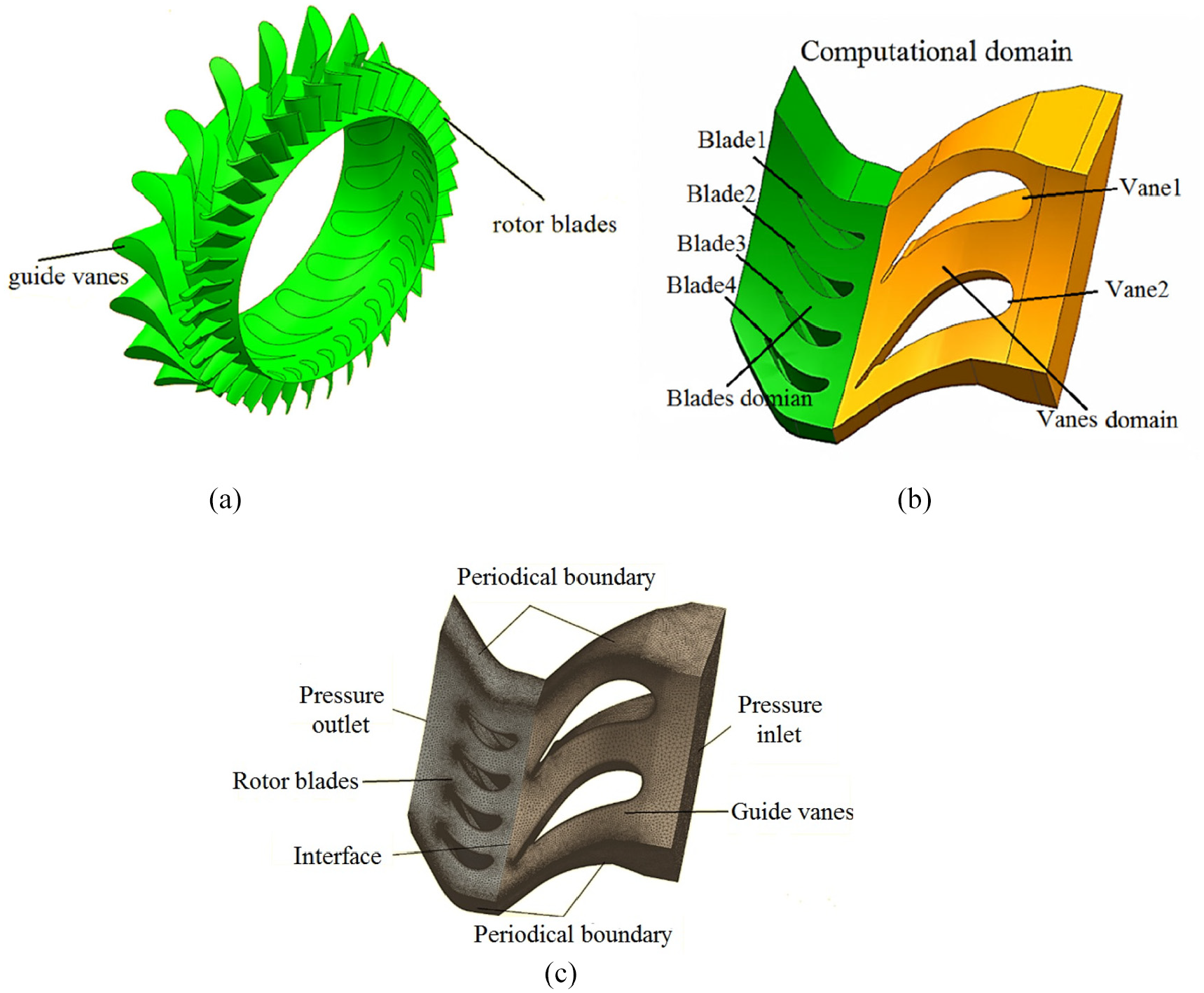
(a) The original geometry of the first stage of the turbine, (b) computational domain and (c) mesh and boundary conditions.
The unstructured grids were generated in the computational domain, and in order to simulate the rotation effect of the blades, the steady simulations were performed with multiple reference frame model (MRF), while the unsteady calculations were performed with sliding mesh model (SMM). The grid independence was investigated by the comparison of the surface pressures of the middle section on a vane surface for three numbers of grids (1.7 million, 2.6 million, and 3.5 million), as shown in Figure 2. The simulated results of the three cases basically overlap, and in order to guarantee the accuracy of the simulation, the case of 3.5 million grids was applied.

Validation of grid independence.
A nonuniform total temperature distribution was assigned on the turbine inlet, as shown in Figure 3. This is a typical temperature distribution for a turbine. The boundary conditions of the inlet and outlet of the domain were pressure inlet and outlet, respectively. There is cooling gas inside the vanes and the heat exchange coefficient between the vane walls and the cooling air was assumed to be a constant. All the other walls were set as adiabatic. The list of the boundary conditions is provided in Table 1. The main properties of particle are provided in Table 2. The motion and deposition of particle with four sizes were investigated respectively.

Vanes inlet total temperature profile.
Boundary conditions.

Particle properties.

The particle deposition is influenced by its motion in the flow. Therefore, in this paper, the steady simulations were firstly conducted to study the particle trajectories. Then the unsteady simulations with the deposition model were conducted to study the particle deposition for different particle sizes. The characteristics of particle trajectories are used to illustrate the particle deposition characteristics.
Validation of deposition model
In order to ensure the reliability of the deposition model, it is necessary to verify the deposition model before using the deposition model for numerical calculation. To test the deposition model, the deposition of particles for the size of 3 μm under different initial particle temperature impacted on a wedge-shaped plate is computed and the results obtained from the numerical model are compared to the experimental results of Crosby et al. 8 Figure 4 shows the comparison results of the capture efficiency obtained from the experiment of Crosby et al. 8 and the numerical simulation in this paper. It can be seen from Figure 4 that the results of both are almost consistent until the inlet temperature reaches 1456 K, then the result of numerical simulation is higher than the experimental result, and this phenomenon is also mentioned and analyzed in Crosby et al. 8 Through their analysis, they thought that this phenomenon may be caused by the partial deposition of particles falling off. Therefore, it can be considered that the deposition model could accurately predict the particle deposition.
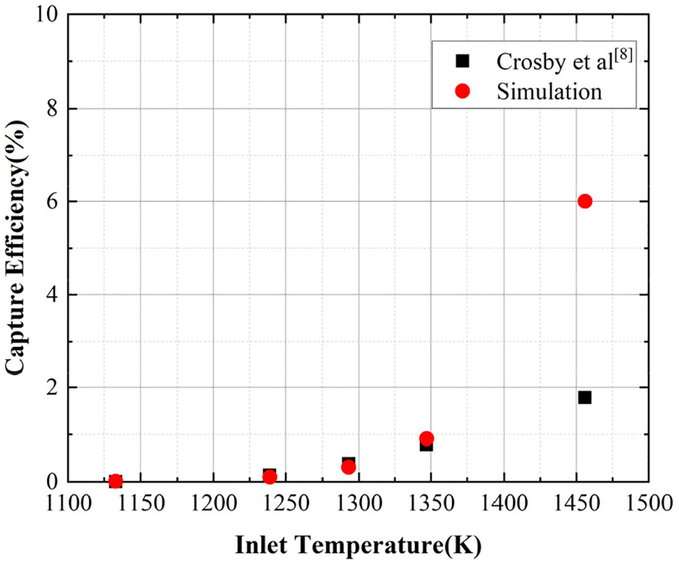
Comparison of the capture efficiency between numerical simulation and experimental results.
Results
Particle motion characteristics
The streamlines and the temperature at the middle section obtained by the steady simulation are shown in Figure 5(a) and (b). From Figure 5(a), it can be seen that the flow is accelerated near the trailing edge of the vanes and then enters the blades domain at a high speed. After the flow entering the blades domain, it is decelerated. The temperature in the vanes domain is higher than that in the blades domain, as shown in Figure 5(b). As a result, a particle has higher temperature in the vanes domain than that in the blades domain and this will affect the deposition probability.

(a) The streamlines and (b) the temperature distribution for on the middle section for steady flow domain obtained by the steady simulation.
Stokes number (St) is a helpful nondimensional parameter for describing particle transport and accordingly discussing the particle deposition. Stokes number is defined as the ratio of the particle relaxation time and the characteristic timescale of the flow

where Uchar is the characteristic velocity of the flow around the obstacle, Lchar is the characteristic length scale of the obstacle (here it is the chord length of the vane), and μ is the viscosity of fluid. This nondimensional parameter can represent the likelihood of a particle to follow the fluid (St<1) or follow a ballistic trajectory (St >1). The Stokes number for each particle size based on the flow parameters on the inlet surface is listed in Table 3.
Stokes numbers for each size.

The motion and temperature of a particle in the flow are two important factors for its deposition and firstly studied here. The trajectory and temperature change of the particle with different sizes in the turbine passage are obtained by tracking the particle. For each particle size, the particles are injected into the flow at the 10 locations on the inlet surface, as shown in Figure 6. Figure 7 shows the trajectories and temperature of particles for different particle sizes in the flow, and the boundary conditions of vanes and blades were set as “reflect” wall when the particles impact on the surface. The 1 μm particles, which have smallest St (0.004) as shown in Table 3, are more readily to follow the flow streamlines as shown in Figure 5(a), and consequently the frequency of particles impacting vanes and blades is low. With the increase of particle size, St number is also increased and the particles tends to follow ballistic trajectories, indicating that it becomes easier for them to deviate from the flow streamlines. As a result, more particles could impact on the vanes and blades. For example, in the vanes domain, the 10 and 20 μm particles all impact on the pressure surface of the vane while no impact occurs on the suction surface of the vane, however, 10 and 20 μm particles show a tendency to rebound and then impact on the suction surface of the adjacent vane. In the blades domain, the impact of 10 and 20 μm particles occurs near the tip of the blade pressure surface. This phenomenon results from the greater particle inertia, which leads to larger centrifugal force imposed on the particle due to the rotation of the blades domain. After impacting the trailing edge of vane’s pressure surface, the 20 μm particles will move a longer distance before entering into the blade domain due to the redound resulted from the greater particle inertia. Then the particles will be driven towards the blade leading edge by the flow.
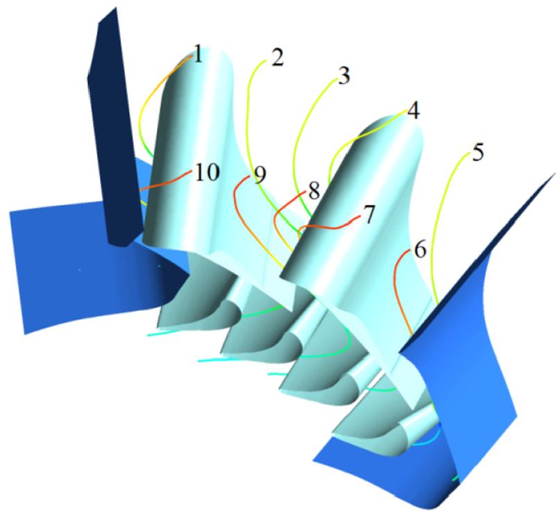
Particle injection locations on the inlet surface.
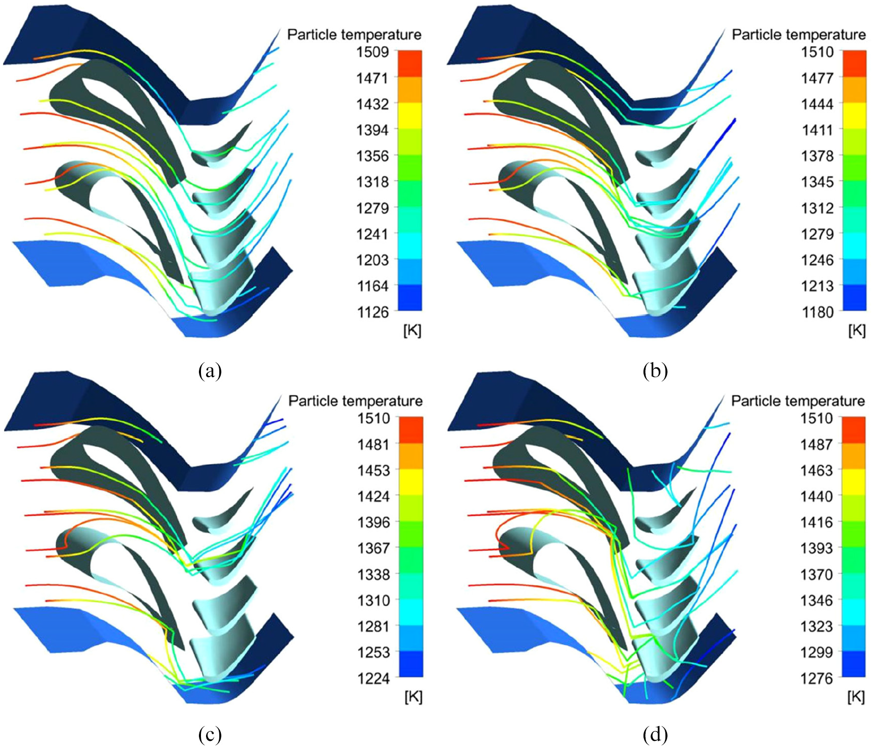
Particle trajectories and temperature for different particle sizes: (a) 1 μm, (B) 5 μm, (C) 10 μm, and (D) 20 μm.
The particle temperature along its path is also affected by its size. Since the mainstream temperature is generally decreased along the passage (see Figure 5(b)), the particle temperature changes similarly along the passage. There is an inverse relationship between the size and temperature drop of the particle traveling through the passage. This phenomenon is due to the fact that the heat dissipation capacity of a particle decreases with the increase of its size, in other words, the particles with larger size have greater thermal inertia and remain at a constant temperature longer than the particles with smaller size, which can also be verified by equation (4). These particles with higher temperature will have a slightly higher probability to stick due to the deposition model.
Deposition characteristics
The temperature distributions of the vane and blade surfaces in the steady flow are presented in Figures 8 and 9. Because the temperature distributions of the vane surfaces obtained by the steady and unsteady simulations are similar, so we only show the steady results here. As showed in Figure 8, the highest and lowest values of vane surface temperature are 1125 and 862 K. While the temperature of vanes near the hub and case is lower, the temperature is both higher at the leading edge and the trailing edge of the vanes pressure surface, and the temperature distribution along the leading edges is similar to distribution of the inlet total temperature. The contours of surface temperature of blades are presented in Figure 9, the highest and lowest values of blade surface temperature are 1383 and 988 K, respectively. The temperature on the pressure surface of the blade is generally higher than that on the suction surface, and the temperature distribution on the pressure surface of the blade decreases gradually from the leading edge to the trailing edge.
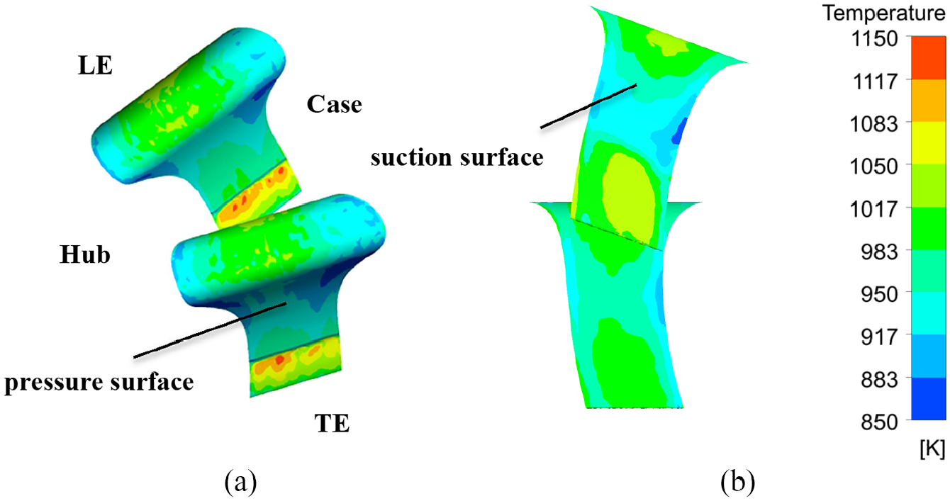
Contours of the temperature on (a) the pressure surfaces and (b) suction surfaces of the vanes.

Contours of the temperature on (a) the pressure surfaces and (b) suction surfaces of the blades.
The deposition for the particles with different sizes are simulated by unsteady method for 0.05 s. For each particle size, a total of 61.3 million particles with the same size are injected uniformly from the inlet into the flow domain. Figure 10 shows the particle deposition distribution on the pressure surface of each vane for the four sizes. Along the spanwise of the vanes, the deposition seems uniform, since the vanes have no rotation and the particles injection is uniform. For 1μm particles, the deposition is less because they could follow the flow streamline very well and have lower probability impact on the vanes, as shown in Figures 5(a) and 7(a). The other reason for this is that the 1 μm particles have the largest temperature drop along the flow passage, and therefore have the lowest probability of sticking to the vanes.

Particle deposition on the pressure surfaces of the vanes for different particle sizes: (a) 1 μm, (b) 5 μm, (c) 10 μm, and (d) 20 μm.
The main particle deposition area expands as the particle size increases. This results from the changes of particle trajectory and temperature caused by the increase of particle size. When the particle size increases to 5 μm, the trajectories of particles became more ballistic compared to the 1 μm particles as shown in Figure 7(b) and more particles could impact on the vanes. The temperature drop for the 5 μm particles along the flow passage are is than that for the 1 μm particles, resulting in higher probability of sticking to the vanes. Therefore, the deposition begins to spread on the leading edge and the trailing edge. This phenomenon is also caused by the profile of the vane pressure surface, for the leading edge is the place where the fluid arrives first, and the trailing edge is the place where the streamlines have a large angle deflection, so the particles will frequently impact these two sites due to inertia deflection. As for the 10 and 20 μm particles, they almost completely deviate from the streamlines of Figure 5(a) due to greater inertia (Figure 7), so the particles can almost directly impact the whole pressure surface. Meanwhile, the temperature of particles impacting the vane’s surface increases with particle size, and the deposition probability of larger particles is also higher, so the deposition for the 10 and 20 μm particles can cover almost the whole leading edge and pressure surface.
The deposition on the suction surface of each vane for the particles with different sizes is shown in Figure 11. It is more difficult for the particles to reach the suction surface of the vane than the pressure surface, leading to smaller main deposition area and less deposition on the suction surface. This is much visible for the 1 and 5 μm particles, as shown in Figure 11(a) and (b). However, for 10 and 20 μm particles, there is a few of deposition on the suction surface of the vane, as shown Figure 11(c) and (d). As shown in Figure 7(c) and (d), some 10 and 20 μm particles could reach the suction surface of the vane by rebounding from the pressure surface of the adjacent vane and consequently may deposit on the suction surface.

Particle deposition on the suction surfaces of the vanes for different particle sizes: (a) 1 μm, (b) 5 μm, (c) 10 μm, and (d) 20 μm.
The deposition distribution on the pressure surface of each blade for the four particle sizes is shown in Figure 12. Different from the deposition on the pressure surface of the vane, the deposition area on blade surface decreases with the particle size. For the 1 μm particles, their small mass makes them subject to little centrifugal force, so the 1 μm particles, having small St number, can follow the flow streamlines well and bypass the vanes to impact on almost the entire pressure surface of blade, as a result, the deposition is gradually spreading. When the particle size increases to 5 μm, the centrifuging effect drives the deposition area concentrating towards the tip of the blade. The deposition of 10 μm particles mainly forms near the blade tip. For the particles of 20 μm, while the deposition on the pressure surface also mainly forms near the blade tip, the deposition is much less than the other sizes of particle, this is due to that the more particles impact occurs on the leading edge of suction surface (Figure 7).

Particle deposition on the pressure surface of the blades for different particle sizes: (a) 1 μm, (b) 5 μm, (c) 10 μm, and (d) 20 μm.
Figure 13 shows the deposition on the suction surface of each blade, the deposition area increases with the particle size. For 1 μm particles, there is no deposition formed because the particles can travel with flow streamlines well so as to make most of impacts occur on the pressure surface. With the increase of particle size, the deviation of the particles from the flow streamlines is aggravated due to the increase of particle inertia (see Figure 7) and this results in the particle impact near the leading edge of the suction surface. Meanwhile, the centrifuging effect also increases with particle size, the deposition also moves towards the tip of the blade.

Particle deposition on the suction surface of the blades for different particle sizes: (a) 1 μm, (b) 5 μm, (c) 10 μm, and (d) 20 μm.
The capture efficiency is an important parameter to measure the deposition and is defined as

The particle capture efficiency for different particle sizes are shown in Figure 14. Figure 14 indicates that total deposition increases with the particle size. But the effect of the particle size on the deposition on the vanes and blades appears some differences. For vanes, the increase of particle size results in a dramatic increase of inertia impact, so lots of particles will be intercepted by the vanes, and the probability of the particle sticking also rises with the increased particle temperature due to the increased particle size, as mentioned above. These two factors make the particle capture efficiency for the vanes keep rising with the particle size. For 1 μm particles, more of them could bypass the vanes and reach the blades, resulting in more deposition on the blades than the vanes. As the particle size increases, less particles could reach the blades and the deposition on the blades become less than that on the vanes. The other reason for this tendency is that for larger particle sizes, the temperature of particles entering the blades domain is lower, leading to lower probability for the particles to stick on the blades. Although the number of particles impacting on the blades gradually became fewer with the particle size, the particles temperature and accordingly the sticking probability increases with the particle size when they enter the blades domain. These two inverse effects on the deposition lead to that the capture efficiency for the blades increases firstly and then decreases with the particle size increasing.

Particle capture efficiency for different particle sizes.
Conclusions
Based on the CFD technique coupled with DPM method, the changes of particle trajectory and temperature for four sizes were studied in the steady flow while the particle deposition for the same sizes was studied in the unsteady flow. The steady results indicate that with the particle size increase, the particle impact also increases due to the increasing inertia, and the temperature drop of the particle travelling through the flow passage decreases. For unsteady results, the increasing of particle size leads to the increasing of the total capture efficiency. On the one hand, the increasing particle size results in the increase of the particle inertia, which makes the particle trajectory ballistic gradually, so the frequency of particle impact and rebound also increase. On the other hand, the thermal inertia of particle increases with the particle size, so the particle deposition probability increases. The joint effect of these two factors causes the increase of the total capture efficiency. But the capture efficiency change with the particle size on the vanes and the blades are different. For the vanes, most of particles with higher temperature impact and deposit the pressure surface firstly, only a few particles with large size may rebound to the suction surface and form deposition on the suction surface. For blades, the centrifuging effect increasing with the particle size increasing force the deposition on the pressure and suction surface to expand towards the blade tip. The capture efficiency on the blades for the particles with larger sizes is much lower than that on the vanes due to less of particles reaching the blades and the lower temperature of these particles. With the particle size increasing, the particles reaching the blades gradually become fewer; however, the temperature drop decreases and accordingly higher deposition probability is produced. Therefore, the capture efficiency for the blades increases firstly and then decreases with the particle size.
Footnotes
Acknowledgements
The authors are grateful to Dr. Yaguo Lyv, Dr. Jianping Hu and Dr. Lifen Zhang, who made some discussions beneficial to the simulations.
Handling Editor: James Baldwin
Declaration of conflicting interests
The author(s) declared no potential conflicts of interest with respect to the research, authorship, and/or publication of this article.
Funding
The author(s) received no financial support for the research, authorship, and/or publication of this article.