
Abstract
In order to solve the low coupling displacement and high crosstalk error of multi-dimensional micro-displacement stage, a two-dimensional micro-displacement stage based on flexure hinges and piezoelectric ceramics is designed and analyzed. The whole stage adopts a nested parallel structure. The design parameters of flexure hinges are calculated using Pseudo-rigid body model. Those parameters are confirmed by a simulation before manufacturing the stage. A double frequency laser interferometer is used for measuring the displacement and crosstalk error of the stage when it’s driven. The experimental results show that the maximum crosstalk error of the two-dimensional displacement platform within full travel is 0.98%, the displacement coupling rate approaches 91.4%, and the remaining trajectory deviation caused by hysteresis asymmetry can be reduced to 0.79%.
Keywords
Introduction
Micro-displacement technology becomes one of the key technologies in the fields of ultra-precision machining, optical instruments, microelectronics, medical technology and so on.1,2 Its displacement stroke and dynamic performance are very importance in the above researches. Current micro-displacement stages use piezoelectric ceramics as the driving element and the deformation of ceramics are guided to displacement through a flexible hinge.3,4 A flexible mechanism is realized by a flexible hinge. The flexible mechanism is a new mechanism for transforming or transferring motion, force, and energy with a small deformation of material.5,6 The flexible mechanism is easy to process, has no gap, friction, and wear, as well as high precision and better transmission efficiency. 7 Thus, the flexible hinge is very suitable to replace the traditional rigid joints as the motion pair of the flexible micro-manipulator. Some researchers have developed multi-degree-of-freedom (DOF) precision stages based on this technology.8,9 These multi-DOF stages are usually adopted parallel or series combination structure. For parallel structure, the stage has a compactly size, and all DOFs act on the same moving surface without cumulative error. However, this structure exists crosstalk displacement error.10–13 Series structure, generally adopts the stack-up type, can realize the independent control of the movements of different degree-of-freedom. 14 This type can avoid the crosstalk displacement error. However, the barycenter of each layer is difference which reduce the bearing capacity and has accumulated error. These lead to system dynamics and rigid will be lower than the parallel structure.
In order to solve the drawbacks of the above structures, a two-dimensional with inner and outer nested series mechanism piezoelectric micro-displacement stage is described. The stage can be driven in xy direction through a flexible hinge independently. The hinges are arranged in parallel to achieve displacement decoupling, which effectively avoids mutual interference in the direction of motion and makes the structure of the piezoelectric stage more compact. In order to ensure that the displacement table has better rigidity and elasticity, the displacement table is made of 45# structural steel, the external dimension is 100 mm × 100 mm × 10 mm, and the whole wire cutting processing is made, so that the platform has a good processing accuracy. Pseudo-rigid body model method is used to derive the stiffness expression and the geometric parameters of the flexible part, and Finite Element Analytical is used for verifying the theoretical analysis results. In order to drive the stage and reduce the hysteresis of piezoelectric ceramic, a charge controller 15 is adopted. The displacement of the stage in x and y direction is measured by a double frequency laser interferometer. The results show the maximum crosstalk error of the two-dimensional displacement platform is only 0.98% within full stroke, the displacement coupling rate approaches 91.4%, and the remaining trajectory deviation caused by hysteresis asymmetry can be reduced to 0.79%.
A low crosstalk error nested two-dimensional micro-displacement stage
The structure of micro-displacement stage
A scheme of the two-dimensional piezoelectric micro-displacement stage described in this paper is shown in Figure 1. S-shape flexible hinges are used as guiding the deformation of piezoelectric ceramics to displacement. Its geometric dimensioning is defined as length L, width W, height H, and width D. The two degrees of freedom of the stage are arranged in a parallel symmetrical structure. The ends of each flexible hinge are fixed to the middle carrying motion platform and the outer frame of the stage. Piezoelectric ceramics are installed in the slots. The platform can move alone the axial directions of piezoelectric ceramics when they are driven.

Structure model of two-dimensional piezoelectric displacement stage.
The stiffness and moving range are determined by the structure of flexible hinges.
13
Therefore, it is necessary to calculates and analyses the parameters of the flexible hinges. The flexible hinges are symmetrically arranged in each axis. As the shape and materials of each flexible hinge are same, only one of the flexible hinges is analyzed. In the following analysis, assuming the material complies with Hooke’s law, the S-shapes flexible hinge is segmented as five segments
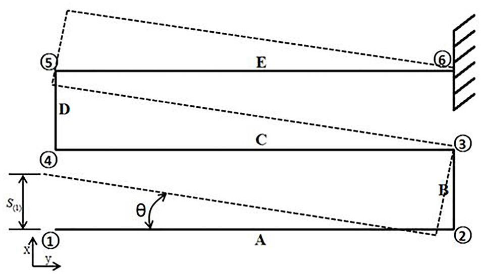
Schematic diagram of S-shape beam structure and deformation of section A.
Under the condition that the used elastic material complies with Hooke’s law, the maximum deflection of a cantilever beam with force at the tip, that is, the displacement S of segment A caused by force F can be calculated as:

Where, E is the elastic modulus and I (

Where Si means the displacement of each segments. The displacements generated by the force of each part are shown in Table 1.
Displacements of each segments.
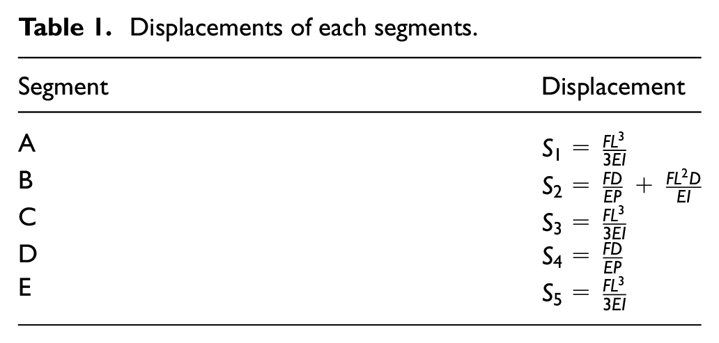
Therefore, the total displacement S(1) is given as:

where, P (P = HW) is the cross-sectional area of flexure hinge; S1, S3, and S5 are the deflection of cantilever beam A, C, and E; S2 and S4 are the deflection of rod B and D under uniaxial load. Equation (3) is the total displacement formula of the flexible hinge under the force F. Therefore, the stiffness of the flexible hinge is given as:

From equation (4), the stiffness coefficient k is a function of the used materials and the structural parameters of flexible hinge, that is, length L, width W, height H, and width D. In this paper, a piezoelectric actuator (the parameters are showed in Table 3) with a displacement of 3.8 μm is used to drive the motion part. Considering our manufacture ability, #45 steel, whose elastic modulus E=210 GPa, Poisson’s ratio μ=0.28, density ρ=7850 kg/m3 and allowable stress σ=340 MPa, is used as the material for flexure hinges. The final machine dimensions of the flexure hinges are according to the displacement of actuator. That is for x direction: L=20 mm, W=1 mm, H=10 mm, and width D=2 mm; for y direction: L=15 mm, W=1 mm, H=10 mm, and width D=2 mm. The stiffness Kx and Ky of xy direction are 1.989 N/μm and 4.575 N/μm respectively, according to equation (4). Because the four flexible hinges are symmetrically distributed as shown in Figure 1, the total stiffness of the displacement platform carried by the four flexure hinges in the direction of x-axis movement is four times than one flexure hinge, that is, the stiffness of the displacement platform in the x-direction is about 7.9542 N/μm, and the stiffness in the y-direction is about 18.299 N/μm. The equivalent mass of the bearing platform is about 0.156 kg, and the natural frequency in the x direction can be calculated to be about 113.65 Hz by putting into the natural frequency calculation formula. By the same calculation, the working stiffness of the displacement table in y direction is about 18.299 N/μm. The equivalent mass of the bearing platform is about 0.117 kg, and the natural frequency in the y direction can be calculated to be about 199.04 Hz by putting into the natural frequency calculation formula. Therefore, it can be seen that the designed two-dimensional micro-positioning platform can be applied to the low-frequency positioning system.
Simulation of the stage using finite element analysis
With the designed parameters, ANSYS finite element analysis software is used to simulate the stiffness and displacement of the stage. With the designed the parameters, a three-dimensional model of the micro-displacement stage is constructed in Space Claim 3D design software. Then the model is imported into the static structure block in the ANSYS software directly. The four screws, in the outside frame as shown in Figure 3, are fixed for limiting freedom motion.

Displacement table model and meshing diagram.
In the simulation, the applied load force relates to the stiffness and desired displacement. In this study, the desired displacement is set us 3.8 μm which is also determined by the stacked piezoelectric ceramics. According to equation (3), the load forces of x and y directions are 30.23 and 69.54 N respectively. Figure 4 shows the cloud map of x and y direction with the applied load force. The stiffness and displacements of x and y direction are shown in Table 2.

The displacement of micro-displacement stage: (a) x motion direction simulation displacement analysis cloud map and (b) y motion direction simulation displacement analysis cloud map.
Comparison of theoretical and simulation results.
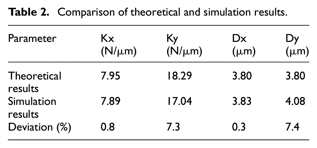
As shown in Table 2, the deviations between theory and simulation of stiffness and displacement in x direction are 0.8% and 0.3%; in y direction are 7.3% and 7.4%. The trends for each direction/axis are same which indicates the availability of simulation.
Through the sensitivity analysis, as shown in Table 3, the mesh size of simulation is independent of the deviation between theory and simulation when it is less than 1 mm.
Mesh sensitivity analysis.

Experiment and results
Experiment setup for testing the proposed stage
The piezoelectric actuators (AE1.65 × 1.65 × 5DF), installed to the proposed micro-displacement stage, are produced by TOKIN. It has a displacement of 3.8 ± 15% μm. The database of the ceramic is shown in Table 4. As piezoelectric ceramics have a certain hysteresis characteristic, a self-developed controller was developed for synchronous high linear operation of multiple piezoelectric actuators. 15 It is a charge controller with a T-type resistor network and operated in open loop. The controller achieves 0.65% positioning error of the piezoelectric actuator with grounding configuration.
Parameters of piezoelectric ceramics.

Figure 5 shows the experimental setup for testing the stage we developed. A double frequency interferometer (Renishaw’s XL-80) is used to measurement the displacement of the stage. The interferometer has a resolution of sub-nanometre. A cube-corner prism is fixed on the stage for reflection the laser back to interferometer. A data acquisition card system (NI cRIO-9030) is used to generate triangle wave and input to the controller.

Experimental setup for testing the micro-displacement stage.
Results and discussion
Figure 6 shows the displacement of the stage measured by interferometer, in the case that only one axis is driven one time. The stage is driven by a triangle wave (frequency: 1 Hz, amplitude 100 V) generated from the controller. It can be seen that the output of interferometer is a good triangle wave which means the stage has a good linearity with the controller. The displacements of x and y directions are 3.892 and 3.995 μm, respectively. Compared with the travel of piezoelectric ceramics (3.8 ± 15% μm), the stage arrived the maximum displacement of the ceramics.

Displacement curve of micro-displacement stage when it is driven by the controller: (a) x direction and (b) y direction.
The displacement deviation of x and y direction between the interferometer and the controller of the stage is shown in Figure 7. The maximum deviation is 31 nm for x direction and 38 nm for y direction. As the controller is operated in open loop, in order to better explain the displacement trajectory deviation of the piezoelectric ceramic, maximum displacement error (MTE) is used. It is expressed as:
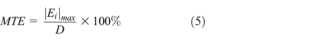
where, |Ei| max is the maximum displacement trajectory deviation, and D is the motion range. As shown in Figure 7, the maximum tracking error (MTE) is 0.79%. These deviations (position errors) may relate to the nonlinear compensation network of the controller as we described in paper. 15

Deviation between the displacement generated by the stage and the generation signal.
In order to measure the crosstalk characteristics of the micro-displacement stage, the x and y direction are driven at the same time using the signal as described in Figure 6. The displacements of stage are also measured using the interferometer. The crosstalk error curve is shown in Figure 8. It can be seen from Figure 8 that when the micro-displacement stage moves in the x direction, the maximum displacement of the micro-displacement platform in the y direction is 0.035 μm; while when the stage moves in the y direction, the maximum displacement of the moving platform in the x direction is 0.039 μm. The crosstalk errors are 0.9% and 0.98% respectively, which proves that this nested series structure can effectively avoid crosstalk displacement.
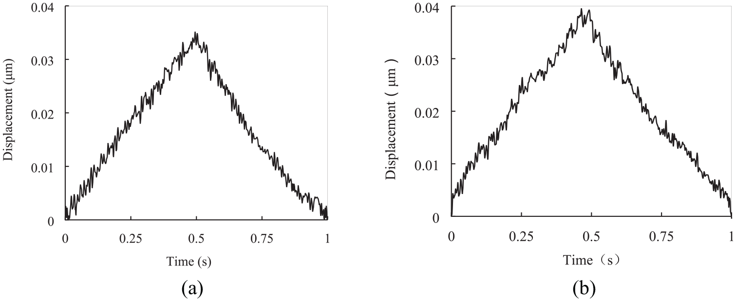
Displacement crosstalk error of the stage when x and y direction are driven at same time: (a) displacement error in the y direction when moving in the x direction and (b) displacement crosstalk error in the x direction when moving in the y direction.
Conclusion
In this paper, a low crosstalk error nested structure two-dimensional micro-displacement stage is designed. The platform has the characteristics of symmetric rigidity, compact structure and low crosstalk displacement error. The whole structure adopts a nested series structure with four flexible hinges arranged symmetrically. The parameters of the flexible hinge are determined by analyzing and verified by finite element simulation analysis. A laser interferometer system is used for measuring the travel and crosstalk error of the proposed stage. According to experimental measurements, the micro-displacement stage has a travel of more than 3.8 μm which means the displacement coupling rate approaches 91.4%, and the crosstalk displacement errors of the two motion directions are only 0.9% and 0.98% which confirms the structure of the stage can effectively avoid the crosstalk problem.
Footnotes
Handling Editor: James Baldwin
Declaration of conflicting interests
The author(s) declared no potential conflicts of interest with respect to the research, authorship, and/or publication of this article.
Funding
The author(s) disclosed receipt of the following financial support for the research, authorship, and/or publication of this article: This research is supported by National Key R&D Program of China (2020YFB2007501).