
Abstract
Mn-Cu high damping alloy is a twin-type damping alloy. Owing to its martensite twin structure at room temperature, it can convert vibration energy into heat energy, thereby reducing vibration. Although essentially a nonlinear elastic material, Mn-Cu damping alloys are treated as linear elastic materials in current engineering practice. However, introducing a constant damping coefficient alone will produce significant errors when modeling vibration reduction characteristics of the material, especially under impact loading. In this study, vibration test was performed on Mn-Cu damping alloy cantilever beam subjected to an impact load and deviation between the test result and the one of existing modeling method was analyzed. A generalized fractional-order Maxwell model was established to describe the nonlinear constitutive relation of the Mn-Cu damping alloy. Then, the model was extended to the three-dimensional state and a secondary development was performed. Finally, various applications for the damping alloy were explored and the effects of the damping alloy on the vibration characteristics of composite cantilever beam structures subjected to impact loads were investigated with the aim of better understanding the dynamic characteristics and improving the effectiveness of vibration reduction applications using Mn-Cu damping alloy in the future.
Introduction
The Mn-Cu high damping alloy is a typical twin-type damping alloy and its main elements are Mn, Cu, Al, Fe, and Ni. Commercially available Mn-Cu based damping alloys include Sonoston, 1 Incramute, 2 ABPOPA, 3 and M2052 (Mn-20Cu-5Ni-2Fe). 4 Among them, the M2052 alloy is characterized by high damping characteristics, high strength (comparable to structural steel), high ductility, and fine processing performance, and therefore, offers the best performance. In addition, M2052 can be directly used as a raw material in mechanical parts and has been extensively applied in vibration reduction applications for machinery, particularly in the military industry. Wang et al. 5 used the Mn-Cu damping alloy in a vibration reduction component for a high-speed rotary fuse-testing machine and tested its dynamic characteristics. The novel Mn-Cu damping alloy was found to have a high stiffness coefficient and effectively reduced the vibration amplitude under high-frequency service conditions and can be used for high-speed rotary equipment. Xin and Mao 6 applied Mn-Cu damping alloy in a remote control weapon station. A simulation analysis was performed on a semi-gear structure and three different vibration reduction schemes were designed. By conducting acceleration attenuation tests on a real semi-gear structure containing the damping alloy, it was concluded that the damping gears effectively absorb vibrations. Wang et al. 7 designed a tribological system with a damping alloy component and demonstrated through experiments and simulations that damping alloy components with a grooved surface can significantly improve vibration suppression, noise reduction, and wear resistance of the system. However, in all of the above studies, the Mn-Cu damping alloy was treated as a linear elastic material and the damping characteristics were modeled by introducing a constant damping coefficient, which does not reflect the nonlinear constitutive characteristics of the Mn-Cu damping alloy.
The high damping characteristics of Mn-Cu damping alloys are derived from two sources: First, during high-temperature melting and cooling, above the Néel temperature, the paramagnetism is transformed into anti-ferromagnetism and anti-ferromagnetic martensite twins are generated; Second, the temperature for producing martensite is higher than room temperature, therefore, stress-assisted martensite is generated under the action of the external force, resulting in interface slip between martensite and austenite parent phases.8–10 These special microstructures and motions absorb vibration energy, resulting in highly nonlinear behavior that is dependent upon temperature, frequency, strain, strain rate, and other factors. Thus, assuming linear behavior limits the application of these models. In general, damping alloys are characterized by an elliptic hysteresis loop, accompanied by more complex nonlinear damping. Many studies on Mn-Cu damping alloys have reported that the damping characteristics are dependent on the vibration amplitude and frequency.9,11,12 Generally, Mn-Cu damping alloys are used in structural components that do not undergo plastically deformation. Nonetheless, the Mn-Cu damping alloy is a nonlinear elastic material and it behavior differs from steel and other linear elastic materials.
To accurately analyze the dynamic characteristics of the Mn-Cu damping alloy subjected to an impact load, the first step is to build a model to describe its nonlinear constitutive relation. To date, only a few studies have investigated the nonlinear constitutive relation of the Mn-Cu damping alloy, which have mainly focused on shape memory alloys and other types of damping alloys. Satisfactory results can be achieved by treating damping alloys as a special type of viscoelastic materials and describing the constitutive relation using the theory of viscoelasticity.13–15
Viscoelastic constitutive models mainly include the Maxwell model, Kelvin model, generalized Maxwell model, and generalized Kelvin model, which are all linear viscoelastic models and are not capable of fully expressing the constitutive relation of nonlinear viscoelastic materials. With the introduction of fractional derivatives, the fractional-order Maxwell model and the fractional-order Kelvin model emerged, making it possible to describe the constitutive relation of nonlinear viscoelastic materials. The normal form of the generalized fractional-order Maxwell model combines multiple fractional-order Maxwell models in parallel, thus further improving the ability to describe nonlinear materials. This has performed well in describing the constitutive relation of nonlinear viscoelastic materials. Sun and Chen 16 described a general linear viscoelastic damper using the generalized fractional-order Maxwell model. The generalized relation between force and deformation of the viscoelastic damper (material) can be depicted within a wide frequency range. In addition, an explicit formula to determine the maximum attainable damping and corresponding optimal model parameters were derived. Costa and Ribeiro 17 tested the dynamic mechanical properties of a carbon fiber reinforced polymer. By fitting the results, a generalized fractional-order viscoelastic model with high correlation and numerical stability was obtained. Based on the generalized fractional-order Maxwell model, Fang 18 proposed a nonlinear constitutive model for a thermotropic shape memory polymer, and described its static viscoelastic behavior in detail. However, the fractional-order Maxwell models described above mainly describe the behavior of viscoelastic fluids and cannot be directly applied to viscoelastic solids. Generalized fractional-order Maxwell models for viscoelastic solids are rarely reported.
Current practice for designing structures used in complex loading environments is to first build a finite element model. The finite element software ANSYS contains a variety of material models and elements that are capable of solving a variety of problems related to nonlinear materials. However, a constitutive model for describing the Mn-Cu damping alloy is not currently available. While the stress relation of damping alloys during loading and unloading is assumed to be linear, hysteresis phenomena occur in the loading and unloading processes. Thus, the constitutive model in ANSYS cannot be used to effectively simulate the mechanical properties of Mn-Cu damping alloy and it is necessary to develop a suitable model.
In this study, to investigate the response of the Mn-Cu damping alloy subjected to an impact load, a cantilever beam was first considered and vibration tests were performed on Mn-Cu damping alloy cantilever beam. Deviations in the results of existing approaches using linear constitutive model and constant damping coefficient from the test results were analyzed. Then, a constitutive equation for the damping alloy was established based on the generalized fractional-order Maxwell model and a secondary development of the constitutive model was performed in ANSYS. Finally, eight different applications for the damping alloy were proposed and their responses to an impact load were investigated, thus providing a theoretical reference for subsequent design of structures incorporating the damping alloy.
Vibration tests of Mn-Cu damping alloy cantilever beam subjected to impact load
Cantilever beam structures are basic structures commonly used in the fields of structural and mechanical engineering. The simple form is convenient for analysis and responses of damping alloy cantilever beam structures subjected to an impact load are representative, to some extent. The effect of temperature on the damping alloy was not considered and all tests were performed at room temperature.
Test material and equipment
A thermally treated M2052 damping alloy plate, mainly composed of Mn–22.1Cu-5.24Ni–1.93Fe, was adopted. Properties of the M2052 damping alloy are listed in Table 1. Spark cutting was used to construct 250 mm × 20 mm × 5 mm cantilever beams from the alloy plate. The length of each cantilever beam (outside of the fixture) was 200 mm and an impact hammer was used for excitation. Due to the large vibration created by the impact load, the accelerometer was fixed to the sample via ∅5 mm mounting holes. The dimensions of the cantilever beams are illustrated in Figure 1. A representative photograph of the cantilever beam is presented in Figure 2.
Properties of M2052 damping alloy.


Dimensions of cantilever beam.
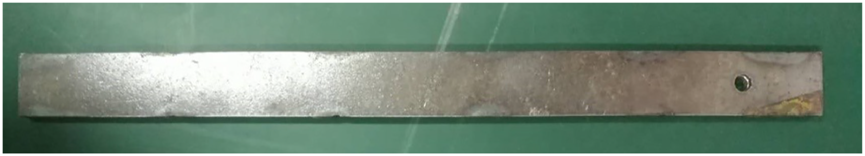
Photograph of Mn-Cu damping alloy cantilever beam.
The main test equipment were provided by Donghua Testing Technology Co., Ltd., including a DHVTC vibration test and control bench, impact hammer, accelerometer, and data collector. Details of the specific equipment models and parameters are provided in Table 2. The sampling frequency was 2 kHz, the data collection mode was 2-channel data collection, and an integral electronics piezoelectric (IEPE) power supply was adopted.
Test equipment.

One end of the cantilever beam was fixed to the bench using a fixture and a length of 200 mm was reserved. The accelerometer was bolted to the test bench via mounting holes. The equipment set up is shown in Figure 3.

Equipment set up.
Testing protocol and analysis of results
One end of the cantilever beam was fixed and an impact load of 100 N was applied to the other end using the impact hammer. The free-end vibration acceleration of the cantilever beam was collected using the accelerometer and quadratic integration was performed to obtain vibration displacement-time curves. Since it is impossible to guarantee load stability with an impact hammer, the test was repeated ten times and average values were calculated. The force spectrum and test results are presented in Figures 4 and 5, respectively.

Force spectrum of impact hammer.

Free-end vibration displacement of Mn-Cu damping alloy beam subjected to 100 N impact load.
As seen in Figure 5, the Mn-Cu damping alloy has a vibration amplitude of 1.352 mm under an impact load of 100 N and regains stability within approximately 0.4 s. To determine the error produced using the ANSYS constitutive model with a constant damping coefficient for calculating the vibration displacement, a finite element model was established for the Mn-Cu damping alloy cantilever beam. One end of the beam was modeled as a fixed constraint and an impact load of 100 N was applied to the other end of the beam. The duration of load application was set to 0.002 s according to the force spectrum. The finite element model of the beam is shown in Figure 6.

Finite element model of Mn-Cu damping alloy cantilever beam.
The simulation time step was 0.001 s with a total duration of 1 s. The constant damping coefficient was 0.06. Material properties used in the simulation are presented in Table 1. The mode superposition method was adopted. A comparison of the simulation results and test results is presented in Table 7.
As seen in Figure 7, the vibration displacement amplitude obtained using the linear elastic constitutive model with a constant damping coefficient is far larger than the real value for the Mn-Cu damping alloy. The vibration displacement amplitude obtained from simulations using ANSYS linear constitutive model was 5.864 mm, with an error of 334%. However, at 0.4 s, the vibration displacement was close to 0, and attenuation of the vibration amplitude was greater than the real value because although the Mn-Cu damping alloy is treated as a liner elastic material in ANSYS, its elastic modulus is only 1/3 that of steel. According to the theory of linear elasticity, structures with a smaller elastic modulus will undergo larger deformation when loaded. Thus, under an impact load of 100 N, the simulated vibration displacement amplitude was much higher than the real value. Furthermore, since a relatively large damping coefficient was set in the simulations, attenuation of the vibration amplitude was also larger compared to the real Mn-Cu damping alloy. This will affect the accuracy of design and application of the Mn-Cu damping alloy. Neglecting nonlinear constitutive relation of Mn-Cu damping alloy is the root cause of the discrepancies.

Comparison of test value of vibration displacement of cantilever beam subjected to 100 N impact load and simulation value obtained by linear elastic constitutive model.
Constitutive model of Mn-Cu damping alloy based on generalized fractional-order Maxwell model
Development of generalized fractional-order Maxwell model
According to the mechanism of high damping characteristics of the Mn-Cu damping alloy, relaxation of the twin structure and friction motion of the stress-assisted martensite are assumed to be between those of elastic motion and viscous motion. The basic form of the Maxwell model was adopted and used to connect one spring-pot element and one spring element in series to create the fractional-order Maxwell model of the twin term and the martensite friction term.
At the microscopic level, twin motion and stress-assisted martensite phase change are both lattice motion deformations driven by an external force; therefore, the strains should be the same and the total stress is the difference between the external force and the elastic force. Two fractional-order Maxwell terms, representing the twin damping term and the martensite friction term, were connected in parallel to express the nonlinear constitutive relation of the M2052 damping alloy. The proposed generalized fractional-order Maxwell model is illustrated in Figure 8.

Generalized fractional-order Maxwell model.
In Figure 8,
Combining the generalized Maxwell model relation and constitutive relation of the fractional-order spring pot 20 yields
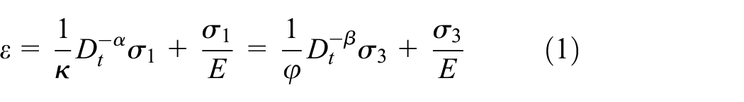
where

Control equation
From a conservation of energy perspective, the work done by the external force that is converted into strain energy at a constant temperature is the sum of the elastic potential energy, twin energy, and martensite-austenite and martensite-martensite friction energies, expressed as

According to J2 deformation theory and Hooke’s law, the energy per unit volume in each case can be expressed as


where
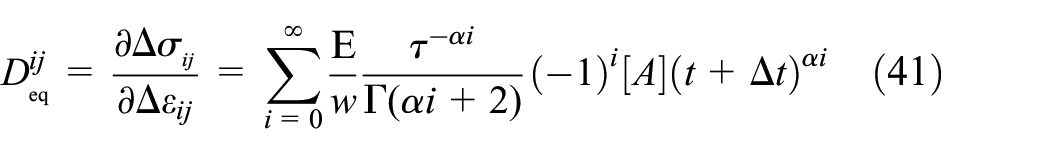
Substituting the above equations into Formula (3) yields the following expression of the control equation:

Formula (4) can be divided into


When

Numerical solution
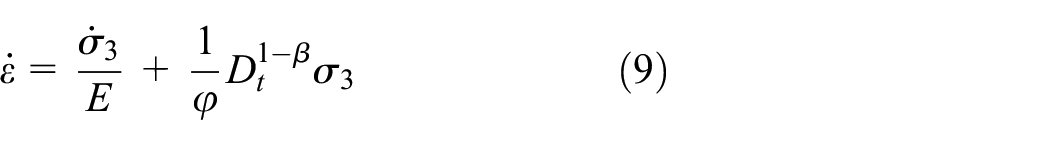
By taking the derivatives of both sides of the control equations, equations (5) and (6), with respect to time, we obtain

To solve the equations, the fractional derivative is discretized using the finite difference method.
After defining
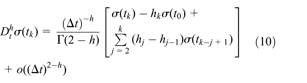
where h is the fractional-order coefficient,
When
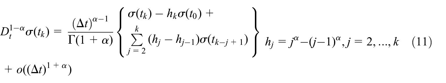
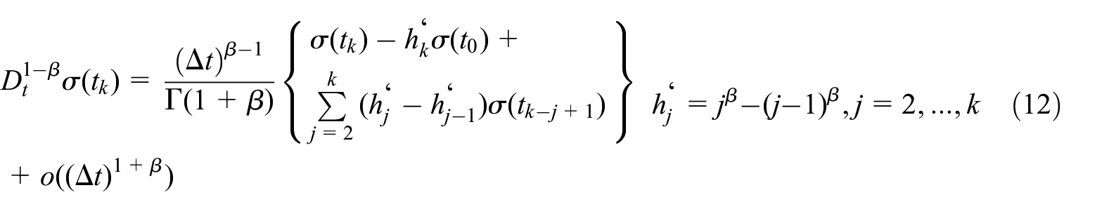
By substituting equations (11) and (12) into equations (8) and (9) and omitting the higher-order error terms, we obtain the finite difference expression for strain rate with respect to twin stress and friction-induced martensite stress:


Through a simplified derivation of Formula (2), equations (13) and (14) can be simplified as

The results of the uniaxial cyclic tensile tests at constant strain rate can be fitted to equation (15) to define various unknown parameters.
Simulation analysis and verification of numerical model
The Mn-Cu damping alloy plate was cut into 150 mm × 20 mm × 2 mm samples and the cyclic tensile tests were conducted on an MTS-Landmark 810 universal testing machine at various strain rates and at the maximum strain amplitude, according to a previously described protocol. 23 Strain was measured with a 50 mm extensometer at a sampling frequency of 10 Hz. The samples were stretched at three fixed strain rates of 0.0025%/s, 0.005%/s, and 0.01%/s up to maximum strain amplitudes of 0.05%, 0.1%, and 0.15%, respectively, and the corresponding stress-strain curves were obtained. The stress-strain curves served as a basis for the simulation analysis and were also used to verify the numerical model. Properties of the M2052 damping alloy are provided in Table 1.
Based on data from the uniaxial cyclic tensile tests at a constant strain rate, the genetic algorithm was adopted to determine the objective function, design variables, and constraint conditions. For instance, the range of the fractional-order coefficient was

Stress–strain curves at various strain amplitudes with a strain rate of 0.0025%/s (

Stress–strain curves at various strain amplitudes with a strain rate of 0.005%/s (

Stress–strain curves at various strain amplitudes with a strain rate of 0.01%/s (
The data presented in Figures 9 to 11 show obvious hysteretic characteristics of the M2052 damping alloy. The hysteresis curves are spindle-shaped with highly significant nonlinear characteristics. At the same strain rate, the damping characteristics increase with increasing strain amplitude and hysteresis becomes more evident. At the same strain amplitude, changes in the damping characteristics with strain rate are not significant but further experimental studies are needed to define a specific law. Fitted data from the generalized fractional-order Maxwell model are consistent with the test data, and the loading and unloading curves are symmetrical about the centerline, which clearly reflects the nonlinear constitutive relation of the damping alloy. The fitted curves were smoother than the test data, and therefore, more suitable for further analyses. Indices used to assess the goodness of fit of the generalized fractional-order Maxwell model are presented in Table 3.
Indices for assessing goodness of fit of generalized fractional-order Maxwell model.

The generalized fractional-order Maxwell model fit well with the test data, with a mean square error of 0.4684–2.651 and a coefficient of determination greater than 0.9929 (Table 3). Furthermore, to more conveniently determine parameter values of the model under different loading conditions within a certain elastic range and without test data, the coefficient averaging method for fractional-order Maxwell models was adopted. 23 Average values of the various coefficients were calculated under three different amplitudes based on the obtained fitted coefficients. Then, expressions for the average coefficient values relative to changes in strain amplitude were fitted and the applicability of the generalized fractional-order Maxwell model was extended. Table 4 presents expressions for the various coefficients of the generalized fractional-order Maxwell model relative to strain.
Expressions of coefficients relative to strain.

Secondary development of constitutive model for M2052 damping alloy using user subroutine
The self-installed material library in ANSYS contains no description of the M2052 damping alloy, therefore, as a prerequisite, user-programmable features (UPFs) of the software were used to write a secondary development using the custom user material (USERMAT) subroutine and to describe the physical properties, damping characteristics, and constitutive relation of the M2052 damping alloy. Then, the finite element software was used to perform a simulation analysis to investigate the dynamic characteristics of the Mn-Cu damping alloy subjected to an impact load.
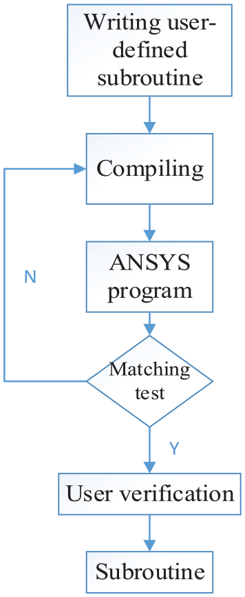
The UPFs in ANSYS refer to the self-installed secondary development platform. The platform is based on the syntax rules of Fortran and designed to offer reprogrammable subroutines and functions to users. In addition, users can create material or element properties according to specific applications, define failure criteria, develop optimization algorithms, etc. More specifically, the primary function of a USERMAT subroutine is to define the constitutive relation of a material and to provide the strain increment and to calculate the stress increment using a user-defined main routine. Thus, a new stress can be obtained and the stress update process can be completed. A flowchart of the USERMAT development process is presented in Figure 12.
Flowchart of USERMAT development process.
Consistent tangent stiffness matrix
The USERMAT subroutine must accomplish two tasks: (1) Calculate the stress increment from a given strain increment, that is, the stress update process; (2) Define the Jacobi matrix of the material, that is, the consistent tangent stiffness matrix. 24
The consistent tangent stiffness matrix can be defined as

where
To solve the consistent tangent stiffness matrix, the main problem of the generalized fractional-order Maxwell model must first be solved, that is, the inconvenience of expressing the finite difference form as the relation between stress increment and strain increment. The solution is to transform the constitutive model and extend the generalized fractional-order Maxwell model from a one-dimensional state to a three-dimensional state.
According to the constitutive equation of the generalized fractional-order Maxwell model, presented in equation (2), we have

When

After defining

The Laplace transform can be applied to both sides of equation (19), as follows (for the convenience, “–” denotes the Laplace transform):


Combined with the transformation presented in equation (2), we obtain

Under stress relaxation conditions, the expression of the relaxation modulus
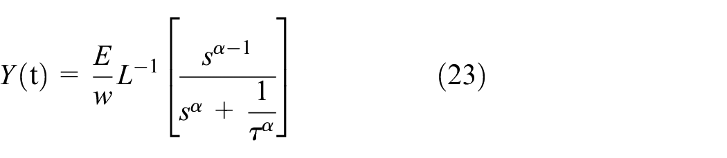
To perform an inverse Laplace transform on the relaxation modulus,
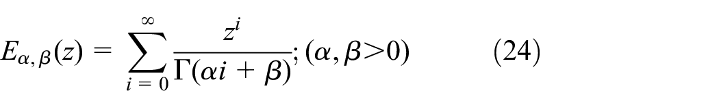
According to Wang, 27 the Laplace transform of the two-parameter M-L function is

where

Then, assuming
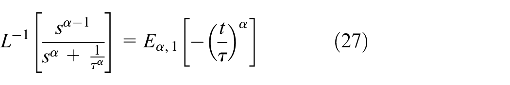
Substituting Formula (27) into Formula (23) yields

Furthermore, according to the definition of Stieltjes convolution: 28
It can be assumed that function


Thus, the Laplace transform of the Stieltjes convolution can be used to define equation (30) and to solve the inverse Laplace transform of equation (22). The definition of Stieltjes convolution, Formula (29), can be used to ultimately obtain the constitutive equation of the relaxation modulus expression of the damping alloy based on the generalized fractional-order Maxwell model. This also solves another problem associated with the original constitutive equation, that is, it is inconvenient to express its finite difference form as the relation between stress increment and strain increment, thereby limiting its application in the secondary development of the finite element program.
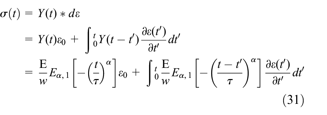
The working range of the damping alloy is within the elastic strain range, and only minor deformation occurs. Thus, the Cauchy stress tensor

where

The integral term in Formula (32) is related to the deformation history, and can be expressed in incremental form according to the Cauchy stress tensor


When
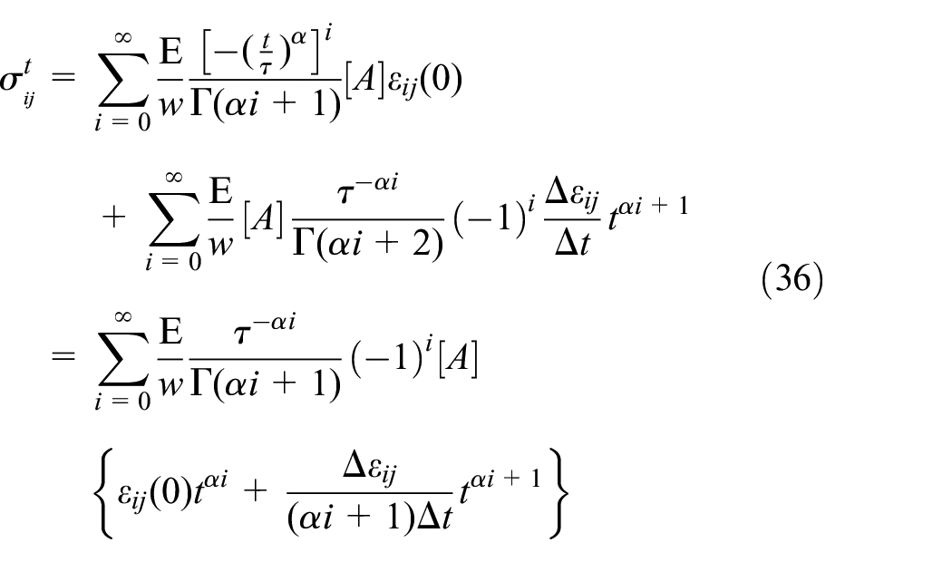

When

Then

Thus, the incremental recursion relation of stress can be obtained as

The consistent tangent stiffness matrix is
Formula (39) is the three-dimensional incremental form of the constitutive equation required to develop the user-defined subroutine; Therefore, equation (40) can be used to calculate the corresponding Cauchy force. The user-defined subroutine development task is used to perform the stress calculations presented in equations (39), (40), and (41) on elements of the finite element model of the material based on the parameters imported from the main routine. Then, the calculated stresses are returned to the main routine.
Verification of user subroutine
To guarantee the correctness of the subroutine, a finite element model of the uniaxial cyclic tensile test was established and the USERMAT subroutine was used to simulate the test conditions in section 2.2. The simulated 150 mm × 20 mm × 2 mm test piece was comprised of 1520 elements and 9053 nodes, as shown in Figure 13.

Finite element model of test piece used in uniaxial cyclic tensile tests.
A reference strain rate of 0.005%/s and a reference strain amplitude of 0.1% were adopted. One end of the tensile sample was defined as the fixed constraint and a constant-speed displacement was applied to the other end to control the load. The boundary conditions are illustrated in Figure 14.
Model constraints.
A comparison of the simulation results and test results is shown in Figure 15.

Comparison of stresses and strains obtained from the uniaxial cyclic tensile test and USERMAT simulation.
As shown in Figure 15, the simulation results are consistent with the real test results, and errors were within 5%, suggesting the subroutine accurately describes the constitutive properties of the M2052 damping alloy.
Dynamic characteristics of various proposed applications of damping alloy cantilever beams subjected to impact load
The damping alloy can be applied in industrial vibration reduction in two ways: first, replacing the overall structure, which is convenient in terms of design, but consumes more material and changes the overall stiffness and damping characteristics of the original component; attaching a damping layer to the surface of the original structure, which consumes less material and can achieve certain vibration reduction effects without affecting the overall stiffness of the original structure, however, the specific application and dosage of the damping alloy must be considered. After the secondary development of the model, the constitutive model of the Mn-Cu damping alloy was used to conveniently compare different applications and alloy consumption rates.
Eight application schemes were proposed based on finite element models for the cantilever beams established earlier in the paper (Figure 16). Details of each application are listed in Table 5.

Finite element models of cantilever beams: (a) single-layer beam, (b) double-layer beam, and (c) sandwich beam.
Applications of damping alloy.

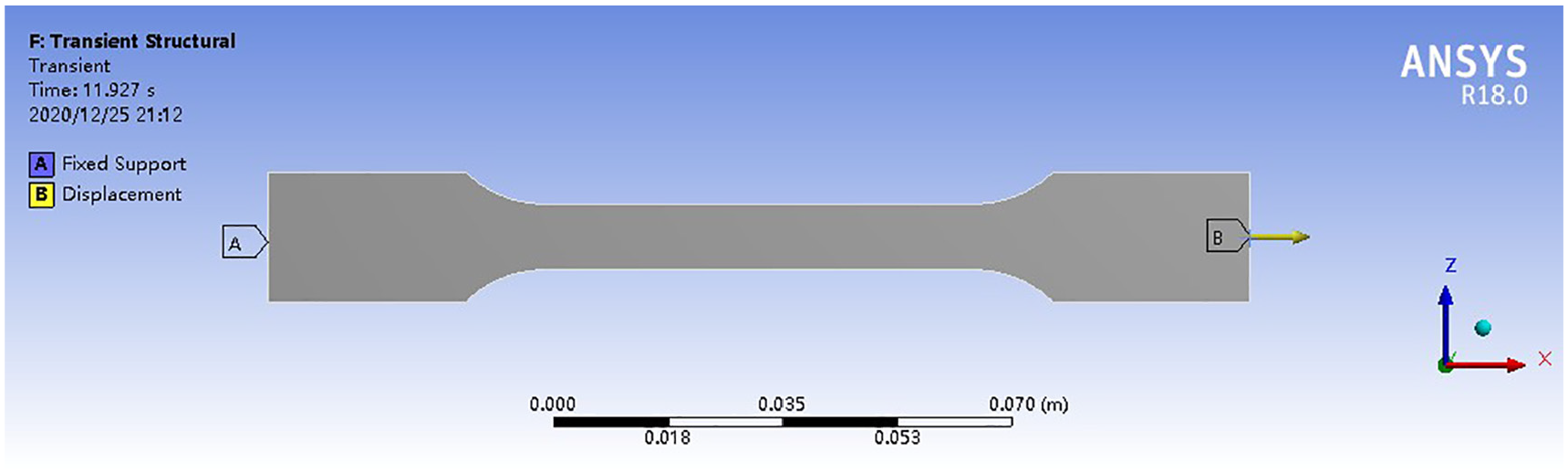
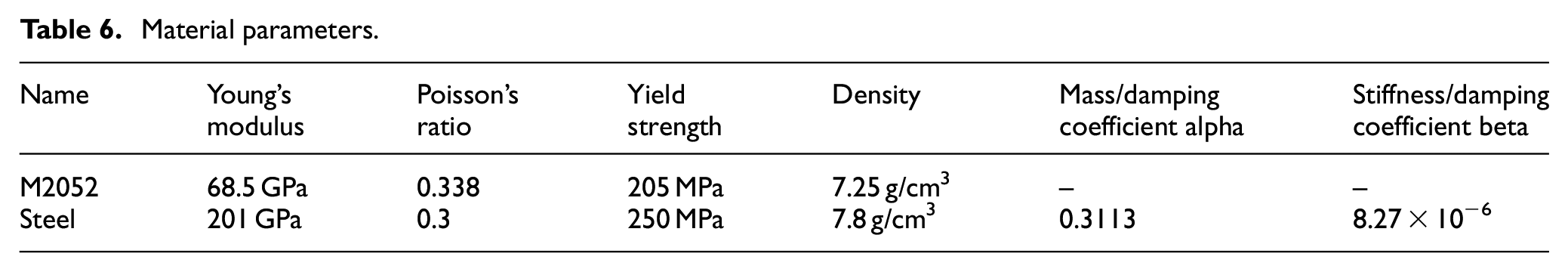
A fixed constraint was imposed on one end of the cantilever beam and an impact load of 100 N was applied to the other end for a duration of 0.002 s. The element type was a solid186 element and the simulation duration was 1 s. The nonlinear Newton-Simpson algorithm was adopted with Rayleigh damping for steel. The damping coefficient of steel was adopted. Table 6 presents the specific material parameters used in the simulations.
Material parameters.
The vibration displacement was monitored at the free end of the cantilever beam. The nonlinear transient simulation results for the single-layer beam are shown in Figures 17 and 18. Figure 17 compares the test and simulation results for a single-layer Mn-Cu damping alloy beam.

Comparison of simulation and test results for single-layer Mn-Cu damping alloy beam.

Comparison of vibration displacements of single-layer beams subjected to impact load.
Results obtained with the USERMAT subroutine of the constitutive model of the Mn-Cu damping alloy agree well with the test values. The simulated maximum vibration displacement was 1.252 mm and the corresponding test value was 1.352 mm, with a relative error of 7%. Consistency between the vibration attenuation time also demonstrated the correctness of the simulation results. Figure 18 compares the vibration displacements obtained for a single-layer Mn-Cu damping alloy beam and an all-steel beam.
As seen in Figure 18, the all-steel beam had a vibration displacement amplitude of 2.016 mm, whereas the M2052 damping alloy cantilever beam had a maximum amplitude of 1.352 mm under the same impact load, that only 67.06% of all-steel beam. The vibration displacement of the damping alloy stabilized at a significantly faster pace compared to structural steel and almost became stable at around 0.4 s, however, the all-steel beam could not restore the initial state after 1 s. Figure 19 compares the vibration displacements of different combinations of double-layer Mn-Cu damping alloy beams subjected to an impact load.

Comparison of vibration displacements of double-layer beams subjected to impact load.
Figure 19 shows that the vibration displacements of the four damping alloy composite beams are different. The maximum amplitudes were all within the range of 1.51–1.65 mm, however, the rate of decrease in the vibration amplitude varied and could be ranked in descending order, as follows: 4 mm composite beam >2 mm composite beam >3 mm composite beam >1 mm composite beam. Clearly, the vibration reduction did not increase linearly with increasing damping alloy content. For example, the 3 mm composite beam had a higher damping alloy content, however, the vibration reduction effect was closer to that of a 1mm composite beam. This was likely because the amplitude is affected by matching of the matrix steel plate and damping layer content under the same excitation. A higher damping alloy content led to lower stiffness and larger deformation, whereas a lower damping alloy content resulted in higher stiffness and less deformation. The amount of deformation was positively correlated with the damping characteristics of the damping alloy. Comparing results for the double-layer beams, it can be seen that the 4 mm damping alloy double-layer beam performed best; however, from a cost efficiency and material processing complexity perspective, the double-layer beam with 2 mm layer of damping alloy had the highest cost performance and its vibration reduction effect was close to that of the double-layer beam with 4 mm layer of damping alloy. Figure 20 compares the results of the sandwich beams.

Comparison of vibration displacement of sandwich beams subjected to impact load.
A comparison of the vibration displacements of the two sandwich beams subjected to an impact load (Figure 20), shows that the M2052 (2 mm) + steel (1 mm) + M2052 (2 mm) sandwich beam exhibits satisfactory damping effects with a maximum vibration displacement of 1.226 mm, which is better than the result for the (1.283 mm) of M2052 (1 mm) + steel (3 mm) + M2052 (1 mm) sandwich beam. The sandwich beams had a higher rate of vibration attenuation and regained stability within about 0.25 s.
To better analyze the vibration displacements of different beam combinations subjected to an impact load, vibration displacement amplitude curves were plotted, as illustrated in Figure 21. Figure 7 shows the vibration response of the cantilever beams in various groups.
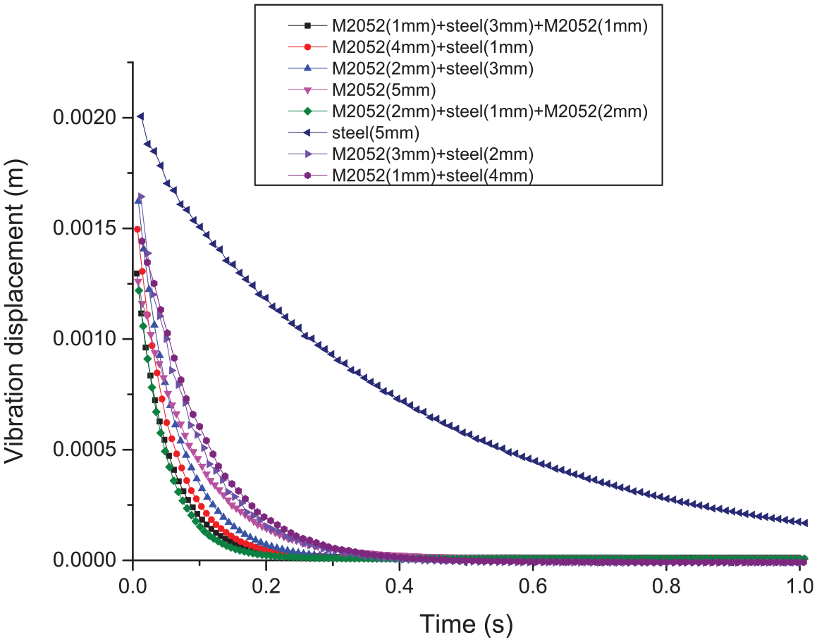
Vibration displacement amplitudes of cantilever beams subjected to impact load.
According to Table 7, for the different beam combinations and consumption rates of the damping alloys, the percentage decrease in the maximum amplitude decline percentage and curvature will change as well. The rate of decrease in the maximum amplitude for the eight application schemes can be ranked in descending order, as follows: 7 > 8 > 6 > 2 > 5 > 3 > 4 > 1. Curvature represents the degree of bending of a curve, and in relation to the angle of vibration amplitude attenuation, represents the rate of attenuation: 7 > 6 > 5 > 3 > 8 > 4 > 2 > 1. In summary, seen from the application forms of the damping alloy, sandwich beams have a larger effect on the vibration attenuation rate than double-layer and single-layer beams. The rates of decrease in the maximum vibration amplitude of the double-layer beams were consistently lower than those of pure damping alloy beams. However, the attenuation rates of M2052 (4 mm) + steel (1 mm) and M2052 (2 mm) + steel (3 mm) were higher than those of pure damping alloy beams, and their vibration reduction effects were superior.
Vibration responses of cantilever beams in various groups.

In combination with the above results for double-layer beams and sandwich beams, four superior schemes were identified: M2052 (4 mm) + steel (1 mm), M2052 (2 mm) + steel (3 mm), M2052 (2 mm) + steel (1 mm) +M2052 (2 mm), and M2052 (1 mm) + steel (3 mm) +M2052 (1 mm). However, in terms of both cost efficiency and vibration reduction effect, the preferred schemes are M2052 (1 mm) + steel (3 mm) + M2052 (1 mm) sandwich beam and M2052 (2 mm) + steel (3 mm) double-layer beam. Although the other two schemes, M2052 (2 mm) + steel (1 mm) +M2052 (2 mm) and M2052 (4 mm) + steel (1 mm), achieved satisfactory vibration reduction effects, the higher damping alloy content is more expensive and causes a substantial decline in the overall stiffness of the cantilever beam.
In order to further verify the simulation results, M2052 (2 mm) + Steel (3 mm) and M2052 (1 mm) + Steel (3 mm) + M2052 (1 mm) composite beams were processed according to the simulation dimensions. The materials were fixed by spot welding, and the impact load vibration test was conducted according to the simulation loading conditions. The physical drawings of the two composite beams are shown in Figure 22.

Photograph of M2052 (2 mm) + steel (3 mm) and M2052 (1 mm) + steel (3 mm) + M2052 (1 mm) composite beams.
Figure 23 shows the comparison between the test and simulation results of M2052 (2 mm) + Steel (3 mm) double-layer beam.

Comparison of simulation and test results for M2052 (2 mm) + steel (3 mm) double-layer beam.
As can be seen from Figure 23, the simulation curve is basically consistent with the test curve. The maximum vibration displacement of M2052 (2 mm) + Steel (3 mm) double-beam subjected to 100 N impact load is 1.476 mm, while the simulation is 1.626 mm, with an error value of 10.16%. However, the experimental amplitude attenuation time of M2052 (2 mm) + Steel (3 mm) double-beam is 0.4098 s, while the simulation is 0.3733 s, with an error value of 8.91%. Figure 24 shows the comparison between the test and simulation results of M2052 (1 mm) + Steel (3 mm) + M2052 (1 mm) sandwich beam.

Comparison of simulation and test results for M2052 (1 mm) + steel (3 mm) + M2052 (1 mm) sandwich beam.
As shown in Figure 24, the maximum vibration displacement of M2052 (1 mm) + steel (3 mm) + M2052 (1 mm) sandwich beam subjected to impact load is 1.253 mm, while the simulation is 1.283 mm, with an error value of 2.39%. Although the vibration of test and simulation all have declined to 0 in 0.32 s, the attenuation rate of test is faster than the simulation at early stage and slower than the simulation at later stage. Due to the influence of the air resistance in test environment, the resistance leads to larger amplitude decay at the early stage. However, as the velocity decreases in the later period, the effect of air resistance also decreases, which results in a slower amplitude attenuation speed. But the simulation doesn’t set the air resistance in the environment. Overall, the simulation results are in agreement with the test results, which verifies the feasibility of simulating the vibration of damping alloy under impact load by the secondary development program of constitutive relation of Mn-Cu damping alloy.
Conclusions
In this study, vibration tests were conducted on Mn-Cu damping alloy cantilever beams subjected to an impact load. Deviations of existing finite element simulation methods for damping alloys from reality were first analyzed, the generalized fractional-order Maxwell model for Mn-Cu damping alloy was established. Next, data from uniaxial cyclic tensile tests at a constant strain rate were used to perform parameter fitting and to verify the proposed model. The generalized fractional-order Maxwell model can satisfactorily reflect the nonlinear constitutive relation of the damping alloy. The constitutive model to the three-dimensional state, a secondary development was performed, and dynamic responses of eight different forms of damping alloy cantilever beams were carried out. Finally, it can be concluded that the preferred vibration reduction scheme for cantilever beam structures should be an attached damping layer on both upper and lower sides of the beam (sandwich beam) or a damping layer on one side. Among the eight schemes, a sandwich beam with a 1mm layer of damping alloy and or double-layer beam with a 2 mm layer of damping alloy beam achieved the best effects in terms of both cost efficiency and damping effects. The results offer a theoretical reference for the future design of vibration reduction-oriented applications using damping alloys.
Footnotes
Acknowledgements
Thanks to all of our colleagues for providing all types of help during the preparation of this manuscript.
Handling Editor: James Baldwin
Author contributions
Conceptualization, R.Z. and Z.W.; methodology, B.M.; validation, Q.Z. and X.H.; data curation, Y.Y. and H.L.; writing—original draft preparation, R.Z.; writing—review and editing, R.Z. All authors have read and agreed to the published version of the manuscript.
Declaration of conflicting interests
The author(s) declared no potential conflicts of interest with respect to the research, authorship, and/or publication of this article.
Funding
The author(s) received no financial support for the research, authorship, and/or publication of this article.