
Abstract
All the time, the wear resistance of TC4 titanium alloy restricts its application in friction parts. In order to solve this problem, in this work, CeO2/Ni60A composite coatings (0, 1, 2, 3, 4 wt.% CeO2) were prepared on TC4 titanium alloy by laser cladding technology. The detection and characterization of the coatings were mainly carried out by X-ray diffraction (XRD), Scanning electron microscope (SEM), Energy-dispersive spectrometer, Vickers hardness test, and wear test. The results showed that appropriate proportion of CeO2 powder could effectively reduce the crack sensitivity of Ni60A coating on TC4 substrate. While the amount of CeO2 powder was 3wt.%, there were no obvious cracks, pores, and other defects in the coating. Coatings mainly consisted of Ti2Ni, TiC, TiB2, Ce2O3, and the substrate α–Ti. CeO2 has negligible influence on the composition of the phase, but it significantly increased the absorption rate of the powder to light, promoted the fluidity of the molten pool. Among five coatings, the average hardness of the 3Ce coating was the highest and the highest hardness value could reach 1163.7 HV0.3, which was 3.58 times higher than TC4 substrate, the friction coefficient was 0.307, and the wear rate was 1.11 × 10⁻⁵ mm3/N m, which reflected extremely high wear resistance performance. Adding an appropriate amount of CeO2 improved the microstructure of the coating, and realized the fine crystal strengthening of the coating.
Introduction
Titanium alloys benefits from its high specific strength, high specific modulus, good oxidation resistance, and corrosion resistance, in recent years, it has been widely used in aerospace, marine and chemical industries.1–4 However, titanium alloy has the characteristics of low hardness and poor wear resistance which limited the use of titanium alloys in industrial sector.5–8 At present, there are many surface strengthening technologies, such as welding, arc ion plating and laser cladding. 9 Among these technologies, laser cladding has the advantages of small deformability and good metallurgical bonding with the coatings.10,11 It has become one of the most promising technology of surface modification, which could significantly improve surface quality of substrate. However, the coating material is quite different from the substrate material. For example, different materials have different thermal expansion coefficient and melting point. Because of the difference of physical properties between substrate and cladding materials, the thermal transformation stress caused by rapid melting and solidification is inevitable. In this case, cracks and voids usually occur in the coating.12,13 In order to reduce the cracking sensitivity of the laser coating and improve the surface quality, many scholars try to add other powders into the original powder. Especially in recent years, rare earth oxides has been demonstrate that it could effectively refine the grain structure, purify the molten pool.14–16 Jianing et al. 17 found that CeO2 could refine Ti-Al intermetallic compounds, generate γ/Cr7C3/TiC composite coating in situ, as well as improve the microhardness and toughness of the coating. Zhang et al. 18 added rare earth Y2O3 to the titanium-based powder, they found that it effectively reduced the residual stress of the coating and reduced the cracking sensitivity of the coating. Zhu et al. 19 found that CeO2 had no significant effect on the phase composition of the TC4/Co/B4C coating, but it could effectively refine the structure.
These studies have a great guiding significance for this paper. When laser cladding technology was used to prepare strengthening coating on the original substrate surface, the thermophysical parameters of strengthening coating material and substrate material should be considered.20,21 If the thermophysical parameters of the two coatings were large, the defects such as pores and cracks would appear in the coating. Although controlling process parameters could alleviate the internal defects, it could not completely avoid this problem. Therefore, rare earth oxide was added to Ni60A powder to reduce the crack sensitivity of the coating and improve the forming quality and performance of the coating. Reinforced Ni-based composite coatings with different CeO2 contents were prepared on TC4 titanium alloy by laser cladding in this article. The microstructure, structure composition, microhardness and wear performance of coating were characterized. Based on these experiments, the tribological characteristics of different CeO2 content were analyzed, and the wear mechanism was explored.
Experiment and methods
Material
TC4 (Ti-6Al-4V) rectangular specimens with a size of 100 mm × 100 mm × 10 mm was used as substrate. The chemical composition (wt.%) of the TC4 alloys was Al 6.03, V 4.01, C0.1, Fe 0.3, N 0.02, O 0.05, and Ti (bal.). The surface of TC4 alloys was sandblasted in order to eliminate the oxide film on the surface. Then, TC4 alloys was rinsed in ultrasonic machine with absolute alcohol solution for 30 min. The chemical composition (wt.%) of the Ni60A powder was C 0.9, Fe 8, B 3.3, Si 4.5, Cr 16, Ni (bal.). The Ni60A powder used in this experiment was spherical, which was conducive to flow in the melting process. Figure 1(a) shows the Ni60A particles (50–150 µm) and Figure 1(b) shows the morphology of CeO2 particles (about 50 nm). The purity of each powder exceeded 99.5%. The planetary ball mill (model: QM-3SP4) was used to mix the Ni60A and CeO2 powders for 3 h at a speed of 250 rpm. Finally, five kinds of CeO2 composite coatings with different content (0, 1, 2, 3, 4wt.% CeO2) were prepared.
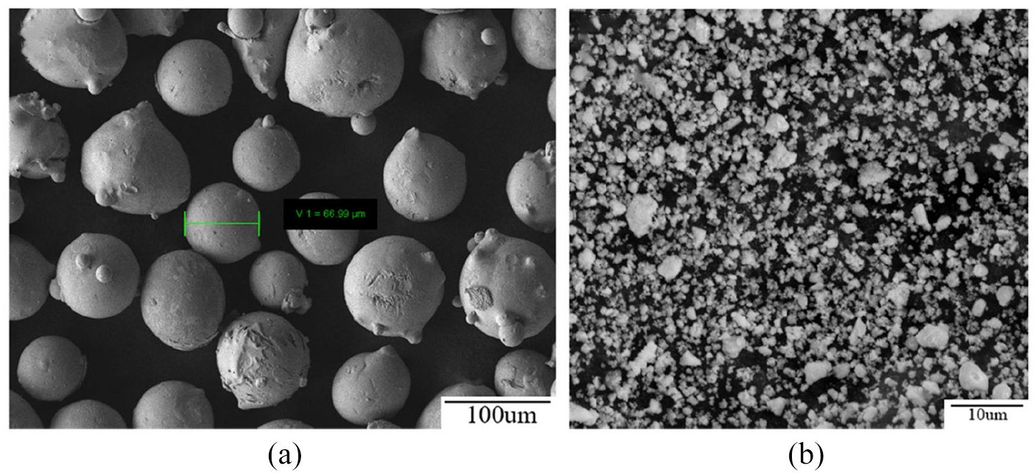
SEM image of the (a) Ni60A powders and (b) nano-CeO2 powders.
Experimental details
In this experiment, TruDisk12003 laser cladding equipment with a 3 KW disk laser was provided by Nanjing Zhongke Yuchen Co., Ltd for laser cladding process. The laser cladding processing parameters were shown in Table 1. Figure 2 was the schematic diagram of laser cladding processing system. The wire cutting machine was used to cut the coating into 15 mm × 15 mm × 10 mm metallographic samples along the cladding direction. Afterwards, the polishing machine was used to polish the coatings until the surface with no scratches. 10 mL HF, 10 mL HNO3, and 80 mL H2O were used as corrosives in the beaker. The dropper was used to drop on the cross-section of the sample, and the surface was corroded for 10–30 s. When light yellow bubble appeared, immediately cleaned the coating with anhydrous ethanol and blow dry.
Parameters for laser cladding process.


(a) Laser cladding processing system and (b) schematic diagram of synchronous powder feeding method.
Microanalysis of the coatings
D2 PHASER X-ray diffractometer (XRD, German), which operated at 40 kV and 150 mA in a diffraction range of 20°–80° and at a scanning velocity of 8° min−1,was used for phase detection of coatings. The scanning electron microscope system (SEM, German) and EDS(German) were used to observe the cross-sectional morphology, microstructure and composition of the coating. Automatic microhardness tester (HVS-1000ZCM-XY, China) was used to measure the microhardness of the coating with the test load of 300 g, holding time: 15 s. The friction and wear tester (RTec MFT-5000, USA) was used to test the tribological properties of the coating and the experimental parameters were shown in Table 2. The white light interferometer (MFP-D, USA) was used to measure the morphology of the wear scar.
Experimental parameters of wear test.

Results and discussion
Phase composition
Figure 3 shows the XRD results of Ni60A particles with different CeO2 content mass fractions of the coatings. It was found that coatings mainly consisted of Ti2Ni, TiC, TiB2, and Ce2O3. When CeO2 was added to the Ni60A powders, it was found that a new product: Ce2O3, was formed in the coating, and the peak of Ti and Ti compound significantly exceeded that of pure Ni60A coatings. Jianing et al. 17 reported that rare earth oxides could purify impurities in molten pool and increase the depth of molten pool. Therefore, it could promote the titanium alloy involved in the melting, which result in more Ti elements entering the molten pool, and promoting the formation of Ti2Ni, TiC, and other reinforcing phases. What’s more, the diffraction peak intensities of Ti2Ni and TiC first increased and then slightly decreased.
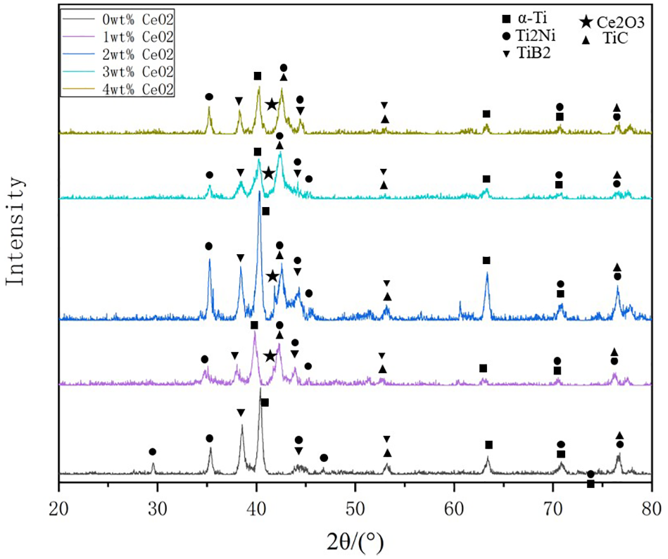
XRD diffraction patterns of laser coating with different CeO2 content.
Under the work of the high-energy laser beam, the TC4 substrate and CeO2/Ni-based composite powder underwent more complex physical and chemical changes in the reaction process of molten pool, which leaded to the formation of different phases.22–24 The reaction equation of was shown below:
Therefore, from the perspective of the phase formation, the addition of different amounts of CeO2 could not change the phase composition of the coatings. However, its addition improved the fluidity of the coating and promoted Ti2Ni, TiB2, TiC, etc. The formation of various hard phases played a critical role in improving the mechanical properties of coatings.25,26
Cracking
In the process of laser cladding technology, the Ni60A powder was melted rapidly by high-energy laser and solidified rapidly after the laser left. During this time, the compressive stress of the coating was generated by heating, and then changed to tensile stress with cooling. 27 This was also the common disadvantage of all rapid prototyping manufacturing technology, once the stress in the coating could not release, it would lead to cracks. 28 At the same time, while the fluidity of the molten pool was poor, the impurities and gases in the molten pool were hard to be discharged during the coating forming process, which lead to the formation of holes. Figure 4 illustrates the cross-section of the Ni60A coating. First of all, it was found that the depth and width of the molten pool increased with the increase of CeO2 content. Therefore, we confirmed that CeO2 could increase the laser absorption of the powder and enhance the energy required to melt the Ni60A powder and TC4 substrate, which was also consistent with the report of Zhu et al. 19 Secondly, without the rare earth oxide, two large cracks occurred in the coating. However, once CeO2 powder was added, the macro morphology of the coating was improved greatly. There was no crack in the Ni60A coating, but some tiny pores occurred at the top of the coating in 2 Ce. As shown in Figure 4(d), It could be found that the width and depth of the molten pool were the largest, and there were no obvious pores. This phenomenon could be explained as follows. Rare earth oxides could improve the compatibility between the substrate and the coating material, which released the residual stress during solidification. In addition, rare earth oxide had the ability of refining the grain, which improved the stability of Ni60A coating. However, the excessive rare earth oxide made the molten pool become viscous. During the solidification process, the impurities in the gas could not be effectively discharged and finally sink into the bottom of the molten pool. Therefore, some pores appeared again at the bottom of the molten pool.29,30

Cross-section of coating with different CeO2 content: (a) 0 Ce, (b) 1 Ce, (c) 2 Ce, (d) 3 Ce and (e) 4 Ce.
Microstructure
Figure 5 reveals the microstructure of Ni60A with different CeO2 addition. It was found that with the increase of CeO2 content, the size of the internal structure of the coating gradually decreased, which proved that the structure had been effectively refined. For example, the black structure in the Figure 5 was α-Ti. While there was no rare earth oxide in the coating, its size was about 10 µm × 10 µm. Compared with the microstructure in Figure 5(d), the size of most α-Ti was less than 5 µm × 5 µm. The grain refinement could be explained as follows. Ce was a kind of element with high surface activity, which could gather on the grain boundary of the structure to reduce the boundary energy and provide the driving force for grain precipitation. In addition, when Ce2O3 accumulated at the grain boundary, it could hinder the grain growth and have the effect on grain refinement. In addition, rare earth oxide CeO2 played a crucial role in improving the dispersion uniformity of the structure. As shown in Figure 5(c), α–Ti was distributed in the upper-right corner, while this problem had been well finished in Figure 5(d) and (e). It was obvious that the aggregated pores appear in Figure 5(e). The reason for the formation of defects was that the fluidity of the molten pool decreased and the coating went through heterogeneous solidification during the formation process.

SEM of coating with different CeO2 content: (a) 0 Ce, (b) 1 Ce, (c) 2 Ce, (d) 3 Ce, and (e) 4 Ce.
To further analyze the microstructure of CeO2/Ni60A coatings, EDS was carried out to identify specific structure. According to the EDS results in Figures 6 and 7, it was found that Nano-Ce element did not appear in mapping scanning results of the 3 Ce coating. The size of rare earth oxide particles was very small, which could not be detected by mapping scanning. But clearly, the fine and white particles distributed on the grain boundary were Ce2O3.

Mapping scanning results of the 3 Ce.

SEM structures of: (a) 0 Ce and (b) 3 Ce.
Figure 7 shows the microstructure of 0 Ce coating and 3 Ce coating and there were four typical phases. As shown in Figure 7, the Ti content of black massive structure was 91.47, so it was inferred to be α-Ti. In Figure 7(a), the content of Ti and Ni in dark texture was 41.00:24.82, which was close to 2:1, so it was inferred as Ti2Ni. According to the atomic composition in Figure 8(c) and (d), the white structure and the black structure (particle shape, needle shape, short rod shape) could be inferred as Ce2O3 and TiC, respectively. TiC and Ti2Ni were both hard phases,31,32 which played a critical role in improving the hardness and wear resistance of the coating. Compared with Figure 7(a) and (b), rare earth element Ce was distributed on the grain boundary, which made the structure refined and more hard phase TiC precipitate. In addition, the TiC in Figure 8(a) appeared as needle shape and dot shape, which was the characteristic of primary TiC. In the process of cladding, primary TiC precipitated directly from the molten pool. However, the nucleation and driving force of TiC degraded with the decrease of bath temperature. Nevertheless, some of the TiC in Figure 7(b) showed as a short rod shape. This phenomenon could be explained as follows. CeO2 increased the laser absorptivity of the powder, leading to more Ti element flow into the molten pool. In addition, the growth state of TiC was affected by the cooling rate of molten pool. At the same time, CeO2 slowed down the cooling rate of molten pool, effectively prolonged the high temperature residence time. Consequently, the hard phase TiC grew more fully.

EDS results of 0 Ce and 3 Ce coatings: Spectrum 1, 2, 3, 4.
Microhardness
Microhardness is usually used as an important index to evaluate the properties of coatings. The hardness distribution of the coating from the top to the substrate was shown in Figure 9. Combining with the XRD analysis, it was found that the existence of hard phases such as TiB2, Ti2Ni, and TiC could significantly enhance the hardness of the Ni60A coatings, which was higher than that of the TC4 substrate (310HV0.3). When the CeO2 content increased, the maximum hardness value of the coating increased from 886.7 HV0.3 to 1163.7 HV0.3. The average microhardness of the 0–4 Ce coating was about 2.50, 2.74, 3.02, 3.58, 3.20 times, respectively. It was found that 3 Ce coating had the best microhardness and at the position about 0.4 mm away from the top of the coating, the hardness even exceeds 1100 HV0.3. According to Hall–Petch equation, when the grains in the coating got finer and denser, the strength and toughness of the coating would be better.33,34

Microhardness of the coatings with different CeO2 content.
It could be seen from Figures 4 and 6 that the addition of CeO2 promoted the formation of Ti2Ni, TiB2, TiC, etc. The formation of these kind of hard phase not only effectively improved the microhardness of the coating, but also enhanced the ability of the coating to resist external deformation. With the increase of hard phase in the coating, the wear rate caused by external force wear decreased.
In addition, it was found that strengthening the fine crystal was also an effective way to improve the mechanical properties of the coating. In the 4 Ce coating, small pores appeared at the bottom again, the stability of the coating decreased and the probability of crack initiation increased. In this way, the microhardness of 4 Ce coating could not continue to increase, it was lower than the microhardness of the coating of 3 Ce, which indicated that excessive addition of CeO2 could not continue to refine the grains. On the contrary, it would reduce the strengthening effect of fine grains. To conclusion, the hardness of Ni60A coating could be effectively improved by adding rare earth oxide in a suitable range.
Wear characteristics and mechanism
Figure 10(a) presents the friction coefficient curve of 0–4 Ce coating. Under the condition of load of 30 N, the sliding friction entered the stable wear stage after a short initial wear. The average friction coefficients of 0–4 wt.% CeO2 coatings were 0.517, 0.412, 0.400, 0.307, and 0.460, respectively. As shown in Figure 10(a), it was found that the friction coefficient of 3 Ce coating was the lowest, which was 68.34% lower than that of 0 Ce. However, the addition of excessive CeO2 (4 wt.%) made the wear resistance decrease. The wear trajectory and wear rate of the Ni60A and 1–4wt.% CeO2/Ni60A coating were shown in Figures 11 and 10(b). The three-dimensional wear morphology of the coating shows that the wear trajectory of the substrate was wider and deeper than the 1–4 wt.% CeO2 coatings. The wear area and wear volume were larger, which indicated that the wear resistance of the coating was better than that of the substrate.

Friction coefficient (a) and wear rate (b) of laser coating with different CeO2 content.

Three dimensional wear morphology of coatings: (a) 0 Ce, (b) 1 Ce, (c) 2 Ce, (d) 3 Ce, (e) 4 Ce, and (f) cross section of wear profile.
The wear rates of the 0–4 Ce coating were 2.13, 1.79, 1.67, 1.11, 1.42 × 10⁻⁵ mm3/(N m), respectively. This also proved that when CeO2 was added to the coatings, the friction resistance of the coatings was first improved and then decreased. The changes in the structure and morphology of different coatings tended to be consistent with the final performance. These findings could be explained as follows. When there were cracks in the coating, the ball tended to expand at the crack, which lead to higher wear rate of the coating. After adding CeO2 powder, as shown in Figure 4, the crack generation had been significantly reduced or completely suppressed. In addition, Ce refined the grains in the internal structure of the coating. Many scholars35,36 had confirmed that the finer the grains in the coating, the higher the quality of the coating. This phenomenon was called fine grain strengthening. Therefore, Ce improved the strength and toughness of the coating, and the high stability made the surface hard to be worn.
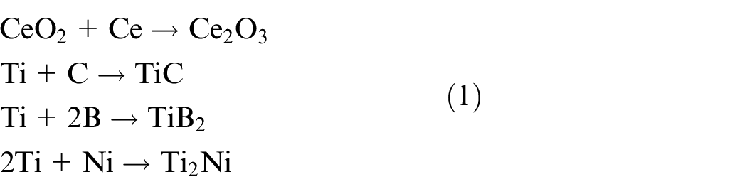
In order to further study the wear mechanism related to CeO2/Ni60A coatings, scanning electron microscope (SEM) was used to observe the wear surface topography of each sample in Figure 11. As shown in Figure 12(a), it was found that the surface of 0 Ce coating was extremely rough after friction and wear test. While CeO2 was not added to Ni60A powder, there were some microcracks in the coating, as shown in Figure 4(a). Generally speaking, when there were cracks in the coating, the surface of the coating was easy to be damaged under the pressure of grinding the ball. The reason for the phenomenon was that under the pressure of normal phase load, the grinding ball tend to press into the surface of the coating at the crack area, resulting in a strong ploughing effect in the sliding process. Under the action of ploughing for 30 min, the crack propagated gradually until a crack with a width of about 4 µm occurred. In addition, the abrasive wear and adhesive wear of 0 Ce coating were exceedingly serious. The accumulated debris caused a significant increase in friction resistance. Once the friction resistance was higher than the strength of the coating or the bonding strength of the coating, the tangential stress would cause brittle spalling of the coating. The better the quality of molten pool during solidification, the higher the wear resistance of the coating. In addition, the hardness of the Ni60A coating (725 HV0.3) was relatively low, which leading to serious micro-cutting action on the surface of the Ni60A coatings by the friction ball. Therefore, the wear mechanism of Ni60A coating was severe adhesive wear and brittle spalling.
The wear surfaces of 0–4 Ce coatings: (a) 0 Ce, (b) 1 Ce, (c) 2 Ce, (d) 3 Ce and (e) 4 Ce.
The forming quality of the coating has been improved effectively by adding CeO2. As shown in Figure 6(b), CeO2 which gathered at the grain boundary could hinder the movement of the grain boundary and reduce the brittleness of the grain boundary, resulted in enhancing the wear resistance of the coating. In this way, the area of brittle spalling area of 1 Ce coating was greatly reduced, and the wear mechanism was adhesive wear and slight brittle spalling. With the increase of CeO2 content, CeO2 refined the structure and improved the hardness of the coatings. Therefore, the ability of the coating to resist deformation had gradually improved. The TiC and Ti2Ni hard phases formed in the coating played an important role. The coarse TiC structure had strong resistance to ploughing deformation. In the process of wear, it could fully resist the ploughing action of friction pair and hard debris. The coarser the TiC grain was, the more the probability of brittle fracture could be avoided. Thus, the wear degree of the coating had been effectively reduced. As shown in Figure 11(c) and (d), it could be found that the wear mechanism of 2 Ce coating was only adhesive wear. In addition,3 Ce coating had the smoothest wear surface without obvious adhesive wear characteristics. The wear mechanism was slight adhesive wear and fine abrasive wear. While the hardness of 4 Ce coating was lower than that of 3 Ce. Due to the addition of excessive CeO2, the number of reinforcing phases in the coating was reduced, 30 and more inclusions were formed, which reduced the microhardness of the coatings. In this case, the wear resistance of the coating decreased, resulting in obvious ploughing and abrasive wear appearing again. The wear mechanism was ploughing wear and abrasive wear.
Conclusion
In order to improve the mechanical properties of TC4 surface, CeO2/Ni60A wear-resistant coating was prepared on TC4 substrate by laser cladding. In this paper, different contents of CeO2 were added to Ni60A powder, and it was found that coatings with different CeO2 content had great influence on the properties of the coating. The main conclusions were as follows:
Rare earth elements did not change the phase composition of the coating, but it mainly exist in the form of Ce2O3. The addition of CeO2 could promote the formation of TiC, Ti2Ni, and other hard phases.
CeO2 could effectively increase the laser absorptivity of the powder and increase the width and depth of the molten pool, making the Ti element in the substrate participate in the molten pool reaction. In addition, CeO2 also reduced the thermal property difference between the coating and the substrate, weakened the initiation probability of cracks and pores in the coating, result in the improvement of the crack sensitivity.
The average microhardness of the 0–4 Ce coating was about 2.50, 2.74, 3.02, 3.58, 3.20 times, respectively, higher than that of the TC4 substrate. CeO2 could be distributed on the grain boundary, which not only refined the grain and limited the grain growth, but also hindered the movement of the grain boundary, so as to improve the wear resistance by reducing the brittleness of the grain boundary. When the content of CeO2 was 3wt.%, the hardness of the coating could reach 1163.7 HV0.3 at 0.4 mm away from the surface.
CeO2 accumulated in the grain boundary hindered the movement of the grain boundary, reduced the brittleness of the grain boundary and improved the wear resistance of the coating. As a result, the wear mechanism of 0 Ce coating was brittle spalling and severe adhesive wear, while that of 3 Ce coating was slight adhesive wear. The wear rate of the 0 Ce coating was 2.13 × 10⁻⁵ mm3/(N m), which was 1.92 times than that of the 3 Ce coating.
Footnotes
Handling Editor: James Baldwin
Declaration of conflicting interests
The author(s) declared no potential conflicts of interest with respect to the research, authorship, and/or publication of this article.
Funding
The author(s) disclosed receipt of the following financial support for the research, authorship, and/or publication of this article: This work was financially supported by Jiangsu Province Mechanical and Electrical Products Recycling Technology Key Construction Laboratory Open Fund Project (No. RRME201902), Ministry of Education’s Joint Fund for Pre-Research Project (No. 6141A0221). The 13th Five-Year Program for the Integration between Industry and Education of Taizhou (2018TZCJ002). The Fundamental Research Funds for the Central Universities (JUSRP121041).