
Abstract
In order to make the speed adjustment system of the permanent magnet synchronous linear motor more stable and make the convergence performance of the speed control system better, a speed regulator based on the terminal sliding mode algorithm is proposed. In addition, the permanent magnet synchronous linear motor will also be affected by temperature changes during its operation. Aiming to enhance the adaptability of linear motors to parameter changes, a terminal sliding mode speed control idea based on adaptive parameter identification is proposed. The Popov stability theory and the mathematical model of linear motor are used to construct a parameter identification system. The identification flux parameters are used as the control algorithm of the terminal sliding mode speed regulator and the update matching of speed regulator flux parameters and motor system parameters are realized. Through the above algorithm, the performance of the entire speed control system is improved. The results of simulation experiments can illustrate the effectiveness of this control method and its effect on improving the control performance.
Keywords
Introduction
The motor described in the paper is a permanent magnet synchronous type. The only similarity between a linear motor and a rotating motor is the operating principle. There is a big difference between the two in the way of movement and the structure of the composition.1,2 The linear motor eliminates the transmission screw, biting gear, etc., converts the rotary motion into linear motion, and eliminates the mechanical transmission structure. The linear motor has a greater improvement in thrust, speed, power, etc.3–5 But linear motors also have shortcomings, such as the nonlinearity of the system, and the fracture effect caused by the specific structure. The strong coupling of the mathematical model, etc., these factors bring greater difficulty to the design of the controller. While satisfying the tracking and regulation performance, it is also necessary to solve the influence of parameter changes on the regulator. In order to further improve the effect of the speed regulator, it is necessary to solve this problem.6–8
In modern control strategies, the sliding mode variable structure control (SMC) algorithm is simple, has a fast response, and is robust to external noise interference and parameter perturbation, especially for the control of nonlinear systems. The SMC algorithm has been continuously developed by scholars in complex control applications. Ren et al. 9 combined adaptively solving boundary problems with sliding mode control, and successfully applied them to the control of brushed motors. Wai and Muthusamy proposed to weaken sliding mode chattering and reduce the system’s requirements for detailed information. A fuzzy neural network genetic sliding mode control strategy is proposed. The combination of strong anti-interference and fast convergence of sliding mode is realized, and the tracking ability of the manipulator is improved. 10 It can be concluded that sliding mode control has strong compatibility with other complex algorithms,11,12 which enables it to give full play to its advantages. In order to avoid the problem of sliding mode control reaching the sliding mode surface in an infinite time, and to further limit the time when the sliding modulus reaches the sliding mode surface, terminal sliding mode control has received attention.
Tran and Kang 13 proposed terminal sliding mode control. It shows better control performance for nonlinear systems, but its resistance to external disturbances is low. Junejo et al. 14 designed a continuous terminal sliding mode speed controller with the goal of limiting the convergence time of the tracking speed, which has improved its convergence time, anti-interference ability, and chattering suppression. However, the controller parameters are fixed, and real-time matching cannot be achieved, resulting in the controller’s weak ability to resist interference from uncertain factors. Panah et al. 15 proposed the use of adaptive estimation of uncertain factors and then combined with sliding mode control to reduce tracking error and improve system accuracy, but its system convergence speed is affected and the convergence time is extended. Wang et al. 16 proposed the use of model reference adaptive algorithm to identify motor parameters, and then use the identified parameters to participate in the current prediction controller. Realize the online update of the parameters in the prediction algorithm. It reduces the static error of the motor current and improves the control performance of the system. Zhang et al. 17 uses MRAS to calculate motor parameters and uses simulation and experiments to prove that parameter identification can correctly converge to the motor parameter values. However, it is only used for parameter observation, and the identification parameters are not combined with the controller application. Li and Chen 18 describes the relationship between temperature and motor parameters when the motor is running. The saturation of the magnetic circuit and temperature changes can have a maximum impact of about 20% on the permanent magnet.
In order to improve the regulator’s resistance to uncertain factors and obtain the desired control effect, the paper proposes a terminal sliding mode speed regulator with adaptive parameter identification. This control method combines the advantages of self-adaptive identification of motor parameters and the finite time convergence of terminal sliding mode control. In addition to making the convergence of the speed error limited in time, an adaptive parameter identification method is also used. It is applied to terminal sliding mode controllers to enable the speed controller to obtain motor parameters and realize controller parameter update. This allows the controller to cope with the influence of the motor parameter changes on the controller, reduces the influence of uncertain external factors on the system, and increases the robustness of the system. Section 4 of this paper gives simulation and experimental results to illustrate the usability of the proposed strategy.
PMSLM mathematical modeling
The PMSLM system is a multivariable, strongly coupled and nonlinear system. 19 For the purpose of understanding the system more conveniently, first make assumptions. Assuming that the magnetic field between the primary and secondary of the linear motor is uniformly distributed, the first step is to determine the mathematical model of PMSLM. The principle structure diagram of PMSLM is shown in Figure 1.

PMSLM principle structure diagram.
Based on the conversion of the rotating coordinate system, there is

where

where

According to the relationship between the electromagnetic thrust and the speed of the linear motor, the motion formula of the linear motor could be obtained follow:

where
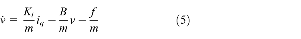
in the above equation,
Speed regulator design
Speed loop terminal sliding mode controller design
Aiming to promote the convergence of the speed regulator and the accuracy of tracking the given speed, 20 a first-order terminal sliding mode speed regulator is designed based on the terminal sliding mode theory. Taking PMSLM as the controlled object and based on TSMC theory, the high-level system is shown as follows:

As shown in formula (6),
For the high-order system shown in equation (6), when the following sliding mode surface is designed, the system will converge within a limited time, namely:

where

For a first-order system,

where

From equations (9) and (10), we can get:

According to equation (7), the design of the sliding surface is:

The selection control law is:

where

Suppose the Lyapunov function is

Slightly sorting out equation (15), we can get:

where
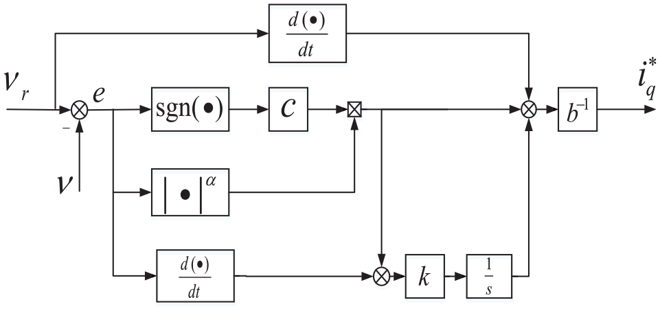
Principle structure of speed regulator algorithm.
It can be seen from equation (13) that among the parameters that affect the output of the control quantity, the value of the flux linkage will directly affect b−1, thereby affecting the output of the current. Figure 7 shows the influence on the current when the flux linkage parameter changes in the controller. When the flux linkage parameter value is changed, the current output also changes accordingly. The change of current affects the stability of the whole system. In this paper, the speed regulator is designed by combining adaptive parameter identification to update the parameters, and further optimize the speed controller.
Adaptive parameter identification
The advantage of adaptive parameter identification is that the algorithm structure is simple and easy to implement.21–23 First, two models need to be established, one is a reference model, which can be obtained by equation (1), and then an adjustable model is established. The form is basically the same as the reference model, but the calculation parameters in the model are identification parameters. The current error models of the two established models are converged by the adaptive law, so that the parameters are consistent, and the identification parameters are estimated. First establish a reference model, and write equation (1) into the form of the state equation as follows:

The differential operator in the above equation is expressed by
Equation (17) is simplified as:

The current in the above formula is expressed as

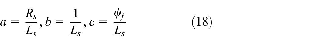
the

where

According to Popov’s stability theory, one of the necessary conditions to make the designed model stable is the positive real matrix

where

Expand and decompose equation (24):
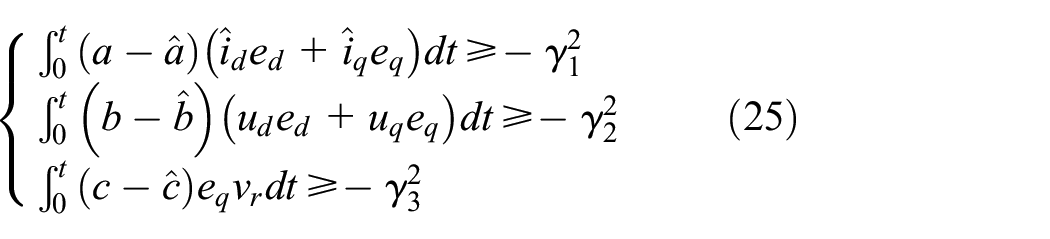
Through the above analysis, if you want to maintain the stability of the system, you need to meet the conditions of equation (25). Taking

Assume a as

Incorporate equation (27) into equation (26):

Decompose formula (28) into two inequalities and discuss separately:

For the first inequality in inequality (29), use the following formula:

Take

Incorporating equation (31) into the first inequality in (29) can make this inequality true. For the second inequality, just take

The derivation process of the adaptive laws for other motor parameters is similar. Through the above description, the adaptive parameter system conforms to the Popov superstability theory and can achieve stability.
Among them,

In the equation,

Schematic diagram of the adaptive parameter recognition algorithm structure.

Block diagram of the overall system design.
System simulation results
The simulation system adopts
Simulation experiment motor parameters.

Figure 5(a)–(c) are the identification waveform results of the magnetic flux linkage, inductance and resistance of the linear motor. When the time is about 0.1 s, the output value of the parameter observer converges to the true value, and the flux, inductance, and resistance. The real values are shown in Table 1. This paper mainly discusses the mutation of the flux linkage and the response of the regulator.
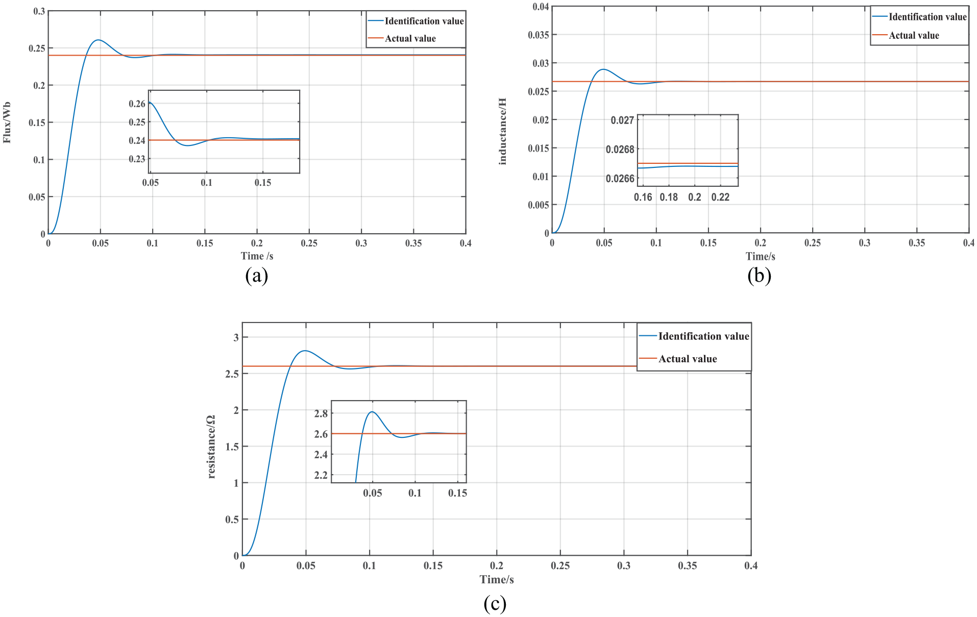
Parameter identification results: (a) flux identification result, (b) inductance identification result, and (c) resistance identification result.
Figure 6 is the tracking of the flux linkage identification result when the motor flux linkage parameter is set to 0.20

Variable flux identification results.
Figure 7 is a comparison waveform of the output current control amount of the speed regulator with online parameter recognition and without recognition. Reduce the value of the motor flux to 0.20
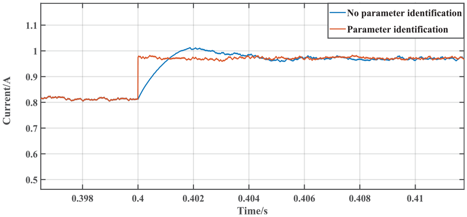
Controlled q-axis current comparison chart.
Figure 8 shows the comparison result of the speed tracking response curve of the speed regulator with and without parameter identification. At 0.4 s, the flux linkage of the motor decreases from 0.24

Parameter identification terminal sliding mode speed comparison.
For the convenience of observation, the speed error waveform get by the terminal sliding mode controller when the without parameter identification of Figure 9 is obtained is a partial enlarged view. At 0.2 s, the load is 100 N, and the motor flux linkage value is changed to 0.20
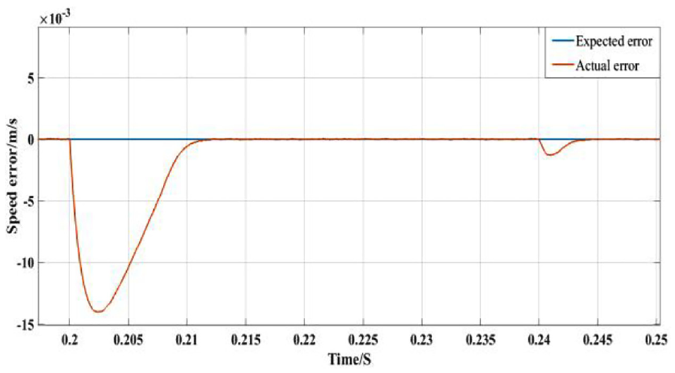
Velocity error waveform.
Figure 10 shows the comparison results of the three speed control methods of PI control, traditional SMC, and TSMC based on parameter identification proposed in this paper. During the motor starting phase, the time for the linear motor to stabilize at a given speed has been significantly improved. In order to facilitate observation, 200 N load is added at 0.2 s. Through comparison, it can be obtained that the speed response curves of traditional sliding mode control and proportional integral control are basically the same, but the anti-load ability of traditional sliding mode is stronger than that of proportional integral method. The terminal sliding mode speed regulator based on parameter identification has relatively good performance in anti-load interference and recovery stability time.

Velocity contrast waveform.
Figure 11 shows the comparison results of the three speed controllers’ steady-state speed errors. Because the controller proposed in this paper contains an integral term in the output nonlinear control quantity, it is equivalent to adding a low-pass filter to the output control quantity, so the overall output chattering is suppressed, so it achieves a better the control effect, thus get the speed waveform with less chattering, make the speed control more stable. However, it can be concluded that the other two control methods do not significantly suppress chattering when the speed reaches a steady state.
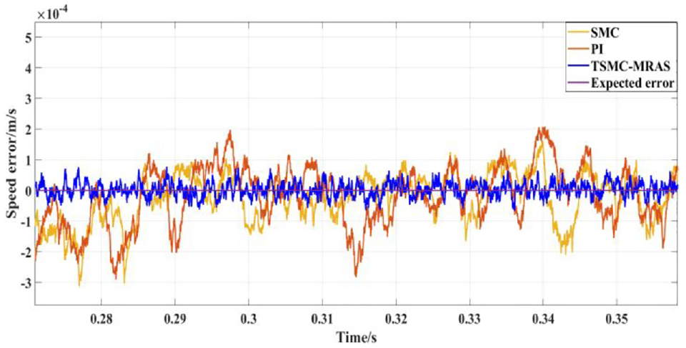
Steady-state speed error waveform.
Figure 12 shows the comparison waveforms of the speed control performance of the three speed controllers. The initial speed is set to 0.8 m/s. When the speed is stable, the rising speed is 1 m/s at 0.1 s, and when the speed reaches a steady state, it decelerates to 0.8 m/s at 0.2 s. During the startup process, the rise time of the terminal sliding mode has a small increase, but compared to the other two controllers, the adjustment time is very small. During the speed-up process, the terminal sliding mode controller has a significant improvement in the convergence speed and overshoot. During the deceleration process, the terminal speed controller has a small overshoot, but the overall tracking effect is better. Converge to the expected value in a short time.

Speed adjustment of different speed controllers.
System experiment
The experimental verification of this article is based on the STM32 development board and Simulation software’s automatic code generation tool. The use of STM32CubeMX software to generate the underlying configuration code allows R&D personnel to focus on the algorithm implementation part and improve work efficiency. The algorithm experiment platform is shown in Figure 13. The permanent magnet synchronous linear motor was used as the controlled object, and the control algorithm c code was generated using a code generation tool, and the algorithm was verified on the STM32 development board.
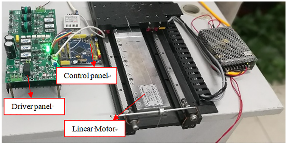
Experimental platform.
For motor parameter identification, due to the fixed structure of the motor, the experiment in this article only gives the parameter identification value when the motor parameters remain unchanged to verify the correctness of the identified parameters. Figure 14(a)–(c) are the identification values of resistance, inductance and flux linkage respectively. Comparing the values in the above linear motor parameter table, it can be seen that the identification results of each parameter converge to the corresponding parameter value within a certain period of time. Its error fluctuates in the range of 4%–6%, which can illustrate the effectiveness of the identification algorithm.

Motor parameter identification results: (a) resistance identification value, (b) inductance identification value, and (c) flux identification value.
Figure 15 shows the speed response waveform when the desired speed of the system is set to 1 m/s. In the start-up phase, the rise time is about 0.01 s, the adjustment time is about 0.02 s, there is a small overshoot, and the overall controller dynamic response index has a good performance. Figure 16(a) shows the comparison waveform of the speed output between the TSMC and the traditional SMC. Add a load of 200 N at 0.1 s to get a load response. As shown in Figure 16, the terminal sliding mode’s anti-load capability and the time to recover stability are better than traditional sliding mode controllers.

Speed tracking waveform.

(a) Speed adjustment experiment waveform and (b) controller output signal.
In terms of speed adjustment, as shown in Figure 16(a), in the process of acceleration and deceleration, the overshoot of the traditional sliding mode is larger and the adjustment time is longer. Figure 16(b) shows the control output signals of the two controllers. It can be concluded from the figure that in the no-load phase, the SMC reaches a stable output at about 0.04 s, while the TSMC-MRAS reaches a stable output at about 0.02 s. In addition, when speed regulation occurs, the control output of this control method is more stable. Through comparison, we can see the effectiveness and superiority of the improved terminal sliding mode speed regulator in linear motors.
Conclusion
With the goal of enhancing the control performance of linear motors, this paper proposes a terminal sliding mode speed regulator based on parameter identification. Combine parameter identification with terminal sliding mode speed regulator. The identification resistance and inductance are used for parameter observation, and the flux linkage value is used to improve the speed controller, so that the terminal sliding mode speed controller can adjust the flux linkage value online, thereby adjusting the control amount and improving the speed output. The parameter identification realizes that the motor parameters are consistent with the controller parameters, enhances the speed regulation and anti-interference ability of the entire system, and improves the system robustness.
Footnotes
Handling Editor: James Baldwin
Declaration of conflicting interests
The author(s) declared no potential conflicts of interest with respect to the research, authorship, and/or publication of this article.
Funding
The author(s) disclosed receipt of the following financial support for the research, authorship, and/or publication of this article: This work is supported by the National Natural Science Foundation of China (No. 51877070, U20A20198, 51577048), the Natural Science Foundation of Hebei Province of China (No. E2018208155), the Talent Engineering Training Support Project of Hebei Province (A201905008), the National Engineering Laboratory of Energy-saving Motor & Control Technique, Anhui University (No. KFKT201901), Hebei Province Graduate Innovation Funding Project (CXZZSS2018085, CXZZSS2019084).