
Abstract
The relative sliding between tooth surfaces is the main cause of tooth wear and power loss, which directly affects the transmission efficiency and durability of gear. The aim of this paper is to provide a method to design such spur gear with low sliding ratio (LSR). Based on kinematics, differential geometry and contact path, the general mathematical models of the generating rack, the pinion and the mating gear tooth profiles are established in turn. Then, according to the relationship between the contact path and sliding ratio, a contact path described by a cubic function is proposed to construct a spur gear drive with low sliding ratio. In order to ensure the continuity of action and non-interference, solid models of the mated gear pair are established, and the motion simulation is carried out by an example. Moreover, the effects of the contact path function coefficients on sliding ratio, tooth shape, and contact ratio are analyzed. Meshing efficiency and tooth wear of LSR gear drive are evaluated by comparing with those of the involute gear drive. The results show that, this LSR spur gear drive has higher transmission efficiency and better anti-wear performance.
Introduction
Spur gear drive, which is an important basic component in the mechanical field, has been widely applied in aerospace, 1 rail transit, 2 engineering machinery, 3 and precision instrument. 4 However, most of the commonly used spur gears have high sliding ratio, which directly affects the transmission efficiency and durability of gear.5–8 Thus, it is very meaningful to find a novel gear pair with lower sliding ratio.
The sliding ratio of the gear drive, which is often considered in the design of novel tooth profile, is mainly determined by the tooth profile. 9 There are many ways to design tooth profile with low sliding ratio. Komori et al. 10 developed a geometric theory of the gears with logix tooth profiles, and when the contact point moves along the tooth height direction, a rolling contact is made at the logical point every few microns. Therefore, the proposed tooth profile has lower sliding ratio than that of involute gear. Using three kinematic parameters: polar angle, polar distance, and rotation displacement, Chang and Tsai 11 provided a parametric tooth profile of spur gears with lower relative curvature and sliding ratio. Kapelevich 12 investigated the design of an asymmetric tooth profile, which has low sliding ratio. Yeh et al. 13 implemented the deviation function (DF) method for the design of the tooth profile and it can obtain lower sliding ratio. Based on the combination of straight line and arc line as contact path, Fong et al. 14 introduced a parametric tooth profile of spur gear. And the sliding ratio can be adjusted within a certain range. Lin 15 proposed a model of the tooth profiles of planar gears is substantially characterized by pressure angle and angular displacement of gears. This model can be regarded as the spur gear with low sliding ratio, but the selection of correlation coefficient is a bit complicated. More recently, Wang et al. 16 analyzed the relationship between tooth profile and sliding ratio, and the proposed tooth profile is established through the given range of sliding ratio. Xu et al. 17 improved the tooth profile of cycloid gear, and the sliding ratio is lower than that of involute gear. Wang et al. 18 presented the tooth profile of internal gear using the given circular arc contact path, and this gear drive has a lower sliding ratio. Liu et al. 19 advanced a design method of tooth profiles based on control of the relative curvature of engaged tooth profiles. By employing this method, the lower sliding ratio can be realized. However, most researches of gear design discuss the characteristic of sliding ratio, rarely considers sliding ratio as the main design goal except Wang et al. 16 And the effect of sliding ratio on the transmission efficiency and wear performance is not sufficiently clear.
In this paper, the low sliding ratio is used as the main design objective to achieve higher transmission efficiency and better anti-wear performance of the tooth surfaces. Firstly, based on kinematics, differential geometry and contact path, general mathematical models for describing the tooth profiles of generating racks, pinions and the mating gears are presented. Then, according to contact path function, the design conditions for LSR gear are given. Through an example design, the solid models of the mated gear pair are established, and the motion simulation is carried out. Furthermore, the effects of contact path function coefficients on sliding ratio, tooth shape, and contact ratio are analyzed. Finally, the transmission efficiency and tooth wear characteristics of LSR gear drive are compared with those of involute gear drive.
Method of constructing tooth profiles
Several basic parameters are defined as follows: (1) the tooth number of driving gear Z1 and of driven gear Z2; (2) the radius of the pitch circle of the driving gear r1 and of the driven gear r2; (3) the module m, which describes the tooth size, defined as two times the pitch radius divided by the number of teeth; (4) the addendum height ha, which describes the tooth height above pitch circle; (5) the dedendum height hf, which describes the tooth height below pitch circle; (6) the radius of the addendum circle of the driving gear ra1 and of the driven gear ra2; and (7) the radius of the dedendum circle of the driving gear rf1 and of the driven gear rf2.
Construction of the generating rack
In order to establish the mathematical models of the conjugated tooth profiles, four coordinate systems are set up as shown in Figure 1. Fixed coordinate system is S(o,x,y) whose origin o coincides with the pitch point P, while rotating coordinate systems attached to the centers of the driving gear and the driven gear are S1(o1,x1,y1) and S2(o2,x2,y2), respectively. The moving coordinate is S3(o3,x3,y3) which attached to the generating rack. At the start position I, S3(o3,x3,y3) coincides with S(o,x,y). The engaged tooth profiles of driving gear, driven gear, and rack are represented by Σ1, Σ2, and Σ3, respectively. The contact path of conjugated tooth profiles is Σ, which passes through the pitch point P. At the start position, the rack tooth profile meshes with Σ1 at point A on the contact path Σ.

Design of conjugated tooth profiles based on contact path.
Assuming that the equation of contact path Σ is expressed in coordinate system S(o,x,y) as:

Similarly, the equation of rack’s profile Σ3 is defined in coordinate system S3(o3,x3,y3) as:

According to the theory of gearing, 20 the equation of rack’s profile can be derived by equation (1) as:

where C is an integration constant specified by the start position of Σ3. For the convenience of solving the value of C, the start position I can be set as the rack’s profile just passes through the pitch point, that is, the start position can be defined as:

Construction of the gear tooth profile
As shown in Figure 1, when Σ3 translates leftwards to the position II from the start position I by the distance L, Σ1 rotates counterclockwise around the point o1 by the angle ϕ1 and meshes with Σ3 at the point B(x,y) of contact path Σ. Moreover, the point B corresponds to point B3(X,Y) of tooth profile Σ3 at the position I. It is easy to know that BB3 = L = X–x. The equation of Σ1 at the start position can be determined by turning point B clockwise around point o1 to arrive at point B1(x1,y1) by ϕ1. Similarly, the equation of Σ2 at the start position can be determined by turning point B counterclockwise around point o2 to arrive at point B2(x2,y2) by ϕ2.
Based on the kinematic relationship between gear and rack, angles ϕ1 and ϕ2 can be defined by equations (5) and (6) as:

If L > 0, then the rack needs to translate leftwards, and point B3 can move to the meshing point B.
Through coordinate transforming, the coordinate of B is calculated in dashed coordinate system S1(o1,x1,y1) as:

where
Consequently, the equation of the driving gear Σ1 can be obtained from equations (3), (5), (7), and (8), which can be expressed as the following equation:
In the same way, the equation of the driven gear Σ2 also can be established by the known contact path as:

As marked in Figure 2, there are four points (D, E, F, and G) on the meshing line, points D and G are the limiting meshing points at the contact path when the tooth profile Σ1 and Σ2 mesh with Σ3. Likewise, points E and F denote the limiting meshing points as the tooth profile Σ1 meshes with Σ2.

Limiting meshing points of conjugated tooth profiles.
According to the theory of gearing, 20 these points can be solved using the following equations (11)–(14), respectively.


Then, the limiting parameters of the effective meshing profile of a pair of teeth can be written as x∈[xE, xF].
Generally, the transition curve c1d1 at the root of the gear can be obtained by the envelope movement of the generating rack’s tip, as depicted in Figure 3. Supposing that the generating rack’s tip coincides with the dedendum at the position I, and the rack tooth profile meshes with the tooth profile Σ1 at the point e1. When the generating rack Σ3 translates rightwards to the position II from I by the distance l, the transition curve can be formed. Moreover, Σ1 rotates clockwise around the point o1 by the angle φ1 and meshes with Σ3 at the point G(x,y) of contact path Σ. The ultimate meshing point G corresponds to the point c1 of tooth profile Σ1 at the position I. It can be seen that Gd1 = l = x.

Transition curve is formed by rack’s tip.
According to the above analysis of the formation process of the transition curve, the angle φ1 is described as

If l > 0, then Σ3 needs to translate rightwards, so that Σ1 can rotate clockwise.
Based on the initial meshing position (at the pitch point P) of rack and gear (see Figure 1), the equation of transition curve of the driving gear and driven gear can be respectively expressed as:


Design conditions for low sliding ratio
Relationships between sliding ratio and contact path
The sliding ratio of the conjugated tooth profiles Σ1 and Σ2 in the meshing plane can be interpreted as, in a particularly short time, the ratio of the relative arc length of the two tooth profiles sliding over the arc length of the tooth profile, as shown in Figure 4. ΔS1 and ΔS2 denote the traveling arcs of profiles Σ1 and Σ2, respectively.

Relative sliding of a pair of tooth profiles.
Referring to Figure 1, BK is the normal of the contact path at point B, where point K is the intersection of BK and center line o1o2, the distance between point K and pitch point P is H. Then, combining Figures 1 and 4, the sliding ratio δ1, δ2 of tooth profile Σ1 and Σ2 can be calculated by the following equation:


where H can be obtained based on the contact path, and it can be expressed as:

In order to realize the lower sliding ratio characteristic of spur gear drive, the absolute values of δ1 and δ2 should be as small as possible. That is to say, the absolute value of H should be as small as possible.
Design of contact path
As is known, the contact path of involute cylindrical gear pair is a linear function, and the sliding ratio of this gear drive is higher. Combined with the first order function meshing path of involute gear drive, the cubic function is introduced to reduce the sliding ratio of cylindrical gear pair. For this, the equation f(x) of contact path can be represented as follows:

where a1 and a2 are the coefficients of contact path function.
Generally, during the meshing process of conjugated gear pair, the meshing motion at the pitch circle is regarded as pure rolling, and the sliding ratio is 0. So, the function f(x) can satisfy the pure rolling condition when the meshing point is located at the pitch point P.
In order to realize the continuous transmission of conjugated gear pair, it is necessary to ensure that the contact ratio ε ≥ 1. And the contact ratio is calculated as the following equation:
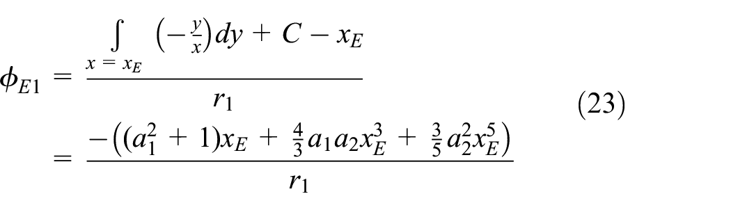
where ϕE1 and ϕF1 can be solved from the following equations based on the limiting meshing points in Figure 2, respectively.

Assuming that f(x) is an odd function, it can not only ensure a lower sliding ratio when meshing at the addendum of tooth, but also ensure a lower sliding ratio when meshing at the dedendum of tooth. As the tooth profile meshing point moves from the pitch point P to the addendum or the dedendum, the sliding ratio will be gradually increased, that is, the absolute value of H will be increased. In other words, in order to obtain a contact path for a low sliding ratio gear pair, as the meshing point moves from the pitch point to the tooth root, f(x) should be decreased and the decreasing speed should be increased. Then, the conditions that the function needs to meet can be described as:

Utilizing equation (25), a1 < 0 and a2 < 0 can be determined. Thence, equation (21) can be further derived as:

Using the contact path to construct the tooth profile, it is necessary to ensure the addendum thickness. Generally, addendum thickness of surface hardened gear is not less than 30% of the module. 21 In a pair of conjugated gears, the addendum thickness of pinion is relatively smaller, so the limiting condition of the addendum thickness st is suggested as follows

Consequently, based on the method of constructing tooth profiles and the proposed contact path, the mathematical models of LSR tooth profiles can be obtained. The working and transition tooth profiles of driving gear can be expressed by equations (28) and (29), respectively. Similarly, the tooth profiles of driven gear also can be represented by equations (30) and (31).


Example design and analysis
Example design
Given the LSR gear drive with a1 = −tan20° and a2 = −0.005, and other basic design parameters are shown in Table 1.
Design parameters of the spur gear drive.

Substituting the above parameters into equations (28)–(31), the solid models of the mated gear pair can be established as shown in Figure 5. Moreover, the coefficients of contact path (a1 and a2), the contact ratio (ε = 1.29), and the addendum thickness of pinion (st = 2.31 mm), which all meet the design requirements. The sliding ratios of pinion δ1

The solid models of LSR gear pair.
Based on the counterclockwise movement direction of the pinion, motion simulation of the mated gear pair is carried out as displayed in Figure 6. It can be observed that the two gears are in meshing without any interference. When a pair of gear teeth enter into meshing, the other pair of teeth have not yet exited meshing. Thence, the necessary continuity of action can be ensured.

Motion simulation of LSR gear drive.
Effect analysis of coefficients
The basic design parameters of LSR gear drive and involute gear drive are listed in Table 1. And the coefficients of the contact path function as shown in Table 2.
Coefficients of the contact path function.

Using these parameters, the sliding ratio and tooth profile shape of the LSR gears and involute gears are calculated as shown in Figures 7 and 8. It can be found that the absolute value of the sliding ratio of the LSR gear drive is lower than that of the involute gear drive. The maximum sliding ratio of the LSR-2 gear drive (0.35) is 79% less than that of the involute gear drive (1.67). Additionally, as the absolute values of the meshing path function coefficients a1 and a2 increase, the sliding ratio and addendum thickness of the LSR gear will be decreased, the dedendum thickness will be increased.

Effects of coefficients on sliding ratio: (a) effect of a1 on sliding ratio and (b) effect of a2 on sliding ratio.

Effects of coefficients on tooth shape: (a) effect of a1 on tooth shape and (b) effect of a2 on tooth shape.
The contact ratio should be taken into consideration while designing the tooth profile. Given the LSR gear with a1∈[−tan25°, −tan10°], a2 = −0.005 and other parameters are shown in Tables 1. Similarly, given the LSR gear with a1 = −tan20° and a2∈[−0.009, −0.001]. Then, the effects of the coefficients a1 and a2 on the contact ratio are analyzed as displayed in Figure 9.
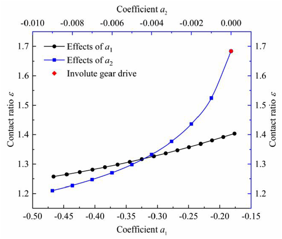
Effects of coefficients on contact ratio.
The results show that the contact ratio will be increased, as the absolute value of the coefficient a1 or a2 is decreased. It can be found that the contact ratio of LSR gear drive is lower than that of involute gear drive. However, this defect can be improved by increasing the addendum coefficient, and the sliding ratio will be increased slightly. It needs to be mentioned, this relatively lower contact ratio does not mean that the carrying capacity of the gear is poor, as shown in the following paper.
Evaluation of meshing efficiency
Improving the meshing efficiency of the gear drive helps to reduce the power loss in the transmission process. Assuming that the friction coefficient of the tooth surface is a fixed value, meshing efficiency of the tooth profile can be defined as the ratio of the power required to overcome the resistance and the driving power.
22
Generally, in the process of single tooth meshing from the dedendum to pitch point, the friction force can provide energy, as shown in Figure 10(a). However, in the process of meshing from the pitch point to addendum, the friction force can consume energy, as shown in Figure 10(b). At some instant, a pair of conjugated tooth profiles Σ1 and Σ2 mesh at point m1 (or m2). Points o1 and o2 are centers of driving gear and driven gear, respectively.

Analysis of the meshing process: (a) the tooth profile within the pitch circle of the driving gear in meshing and (b) the tooth profile outside the pitch circle of the driving gear in meshing.
Based on the above assumption, the instantaneous meshing efficiency during these two meshing processes of can be represented by equations (32) and (33), respectively.

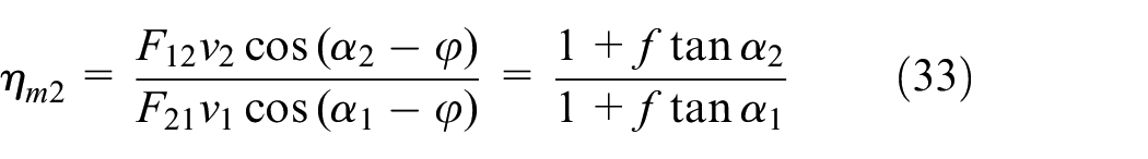
here f = tanφ is friction factor, φ is the friction angle and let f = 0.1.
As the load distribution is ignored, the instantaneous meshing efficiency during the meshing process can be calculated by the contact path as the following equations:

Considering the contact ratio and load distribution, the instantaneous meshing efficiency during the double-tooth-pair period can be evaluated as the following equation:

where FN1, FN2 are the load on the two meshing teeth of the driving wheel. Similarly, η1, η2 are the instantaneous meshing efficiency of each tooth.
Average meshing efficiency also can be used to describe the meshing efficiency characteristics of a pair of gears. Since the meshing efficiency is a function of the angle ϕ1, the average meshing efficiency can be expressed as

Given the LSR gear with a1 = −tan20° and a2 = −0.005, the involute gear with a1 = −tan20°, a2 = 0 and other parameters are shown in Table 1. According to the equation (34), calculations of instantaneous meshing efficiency for two gear drive are presented in Figure 11(a). Ignoring the load distribution, the instantaneous meshing efficiencies of LSR tooth (97.38% and 97.68%) are higher than those of involute tooth (96.83% and 97.12%) at the dedendum and addendum.
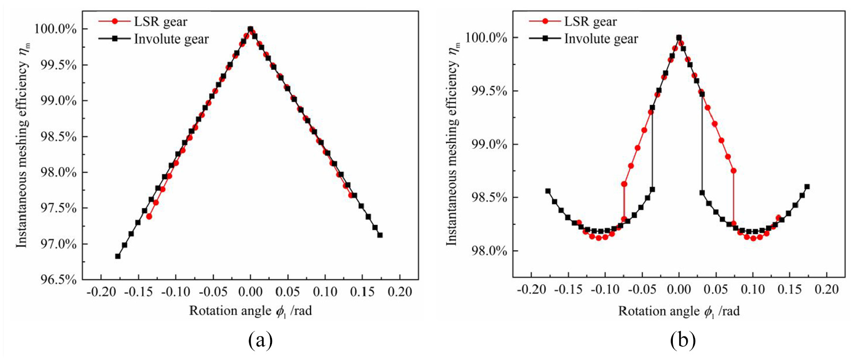
Analysis of instantaneous meshing efficiency: (a) ignoring load distribution and (b) considering load distribution.
As the contact ratio and load distribution are considered, let the elastic modulus E = 200 GPa and Poisson’s ratio v = 0.3 of the material, the torque load 100 N·m on the driving gear, the effective contact tooth width B = 10 mm and other parameters are shown in Table 1. The load distribution is calculated by the material mechanics method. 23 At the dedendum and addendum, the instantaneous meshing efficiencies of LSR gear are lower than those of involute gear as shown in Figure 11(b) due to the contact ratio and load distribution. However, it is necessary to be mentioned that the average meshing efficiency of LSR gear drive (98.81%) is higher than that of involute gear drive (98.58%), as calculated by equation (36).
Analysis of tooth wear
During the gearing process, tooth surface wear occurs due to the relative sliding between tooth surfaces. The Archrad’s 24 wear equation is widely used in tooth wear modeling, which can be represented as:

where V is the wear volume, S is the relative sliding distance, W is the normal load at the contact position, H is the hardness of the contact surface, and K is the dimensionless wear coefficient.
Generally, the position of each meshing point and the relative sliding distance are changing periodically during the gearing process, so the continuous profile can be discretized and the wear model at each meshing point can be expressed as

where t is the time, the tooth contact area is A, the wear depth is h, the relative sliding velocity is v, and the contact stress is p at the contact point.
From equation (38), the wear ratio Ih is defined as

where the wear coefficient k = K/H is influenced by material properties, surface roughness, lubrication conditions, and operating conditions. 25 In this paper, the wear coefficient k is assumed to be a specific value.
There are single-tooth-pair period and double-tooth-pair period in one meshing cycle, so the load distribution on the gear tooth needs to be considered. And the normal load W can be solved by using the mechanical methods of materials. 23 Based on Hertz contact theory, the maximum contact stress p of teeth can be calculated as

hear, Ee = 2[(1 − v1)2/E1 + (1 − v2)2/E2]−1 is the equivalent modulus of elasticity, where Ei (i = 1,2) is the elasticity modulus of material, vi (i = 1,2) is the Poisson’s ratio of material. Re = 2[1/R1 + 1/R2]−1 is the equivalent radius of curvature of the contact point on the meshing tooth profiles, where Ri (i = 1,2) is the radius of curvature of tooth profiles. B is the Contact tooth width of meshing tooth surface.
At any moment, the relative sliding distance S of the tooth 26 is given as follows:

where δ is the sliding ratio of the meshing point, a is the half-width of the elliptical contact region which is expressed as:

The total friction distance SI between the tooth surfaces during the transmission process can be calculated as the following equation:

where n is the rotating speed, t is the total running time.
Therefore, the amount of wear depths hI at each point of single tooth profile can be expressed as

Given the LSR gear with a1 = −tan20° and a2 = −0.005, the involute gear with a1 = −tan20°, a2 = 0 and other parameters are shown in Tables 1 and 3. Based on the mentioned analytical model of tooth surface wear, the pinion tooth wear characteristics of LSR gear drive and involute gear drive are compared, as shown in Figures 12 to 15.
Materials and operating parameters of gear drives.


Curvature of engaged tooth profiles in one meshing cycle.

Maximum contact stress in one meshing cycle.

Wear ratio of single tooth profile.

Wear depth of single tooth profile.
From Figures 12 and 13, it can be seen that the contact stresses of LSR gears are significantly better than those of involute gears, especially at the dedendum and addendum. The reason for this is that the contact form of LSR gear is concave-to-convex, while the contact form of the involute gear is convex-to-convex. At the dedendum, the wear ratio and wear depth of LSR gears (0.0004 μm/s and 0.0036 mm) are significantly lower than those of involute gears (0.0011 μm/s and 0.0207 mm).
Conclusions
This paper has presented a design method for spur gear associated with low sliding ratio. According to the analysis and results, the conclusions are as following:
Based on the contact path, general mathematical models of a pair of conjugated spur gears tooth profiles are established, including the working tooth profiles and the transition profiles, especially the limiting meshing points.
In order to realize the low sliding ratio characteristics of the proposed gear pair, a simple cubic function f(x) = a1x + a2x3 is proposed to describe the contact path. And the coefficients a1 and a2 are based on the sliding ratio δ1 = δ2 = 0 at the pitch point, the contact ratio ε ≥ 1, the addendum thickness st ≥ 0.3 m, and the sliding ratio of the limiting mesh points should be as low as possible.
Solid models of the mated LSR gear pair are established by an example, and then the motion simulation is carried out to verify the characteristics of continuous transmission. Moreover, the effects of cubic function coefficients on the characteristics of the proposed gear are analyzed. The results show that when the coefficient a1 or a2 is increased, the sliding ratio, tooth tip thickness and contact ratio will be decreased.
LSR gear drive has higher average meshing efficiency than that of involute gear drive. As a result, LSR gear drive will exhibit higher transmission efficiency in multi-stage gearing systems especially.
LSR gear drive has better tooth surface contact characteristics due to the convex-to-concave contact form. Moreover, the contact stress, wear ratio, and wear depth of LSR gears are significantly lower than those of the involute gears at the dedendum.
In summary, this paper can provide a reference for the design of LSR spur gear with higher transmission efficiency and better anti-wear performance. The results of LSR spur gears designed by the proposed method have shown some interesting properties, which need to be further exploited.
Footnotes
Acknowledgements
The authors also sincerely appreciate the comments and modification suggestions made by the editors and anonymous referees.
Handling Editor: James Baldwin
Declaration of conflicting interests
The author(s) declared no potential conflicts of interest with respect to the research, authorship, and/or publication of this article.
Funding
The author(s) disclosed receipt of the following financial support for the research, authorship, and/or publication of this article: This work was supported by the National Key R&D Program of China under Grant No. 2019YFB2004700, the National Natural Science Foundation of China under Grant No. 51775264, and the National Defense Basic Research Program of China under Grant No. JCKY2019605D003.