In this paper, the axial arc tooth profile cylindrical worm drive is proposed, whose worm is cut by turning tool. Due to the simple processing equipment, short manufacturing time and low cost, this kind of worm can replace the cylindrical worm ground by grinding wheel under some conditions. The meshing theory of the worm drive is founded comprehensively. Moreover, a movable orthogonal frame is established on the non-orthogonal parametric curves net helical surface. Based on the founded meshing theory, the simulating study on the meshing quality of the worm drive is performed systematically. The numerical outcome shows that the meshing quality of this worm drive is quite favorable, and the condition of forming lubricating oil film is excellent. The working orthogonal clearance of the turning tool is decreased with the increase of the worm thread number, which must be a positive value in the process of worm cutting. This explains that the number of the worm thread is ≤4.
In 1932, the arc cylindrical worm drive was invented by Merrit of David Brown Company.1 This type of worm drive was used for replacing the Archimedes worm drive to overcome disadvantages, such as low transmission efficiency and short service life. The axial arc tooth profile cylindrical worm drive is a branch of the arc cylindrical worm drive, as shown in Figure 1.
Axial arc tooth profile cylindrical worm drive.
The axial arc tooth profile cylindrical worm is cut by a lathe tool with an arc cutting edge. In the process of the worm cutting, the lathe tool makes a relative screw motion along the worm axis, and trajectory surface of the cutting edge forms the worm helical surface.2,3
Because of its simple processing equipment, short manufacturing time and low cost, it attracts scholar to research this type of the worm pair.4–6 Wu et al.1 deduced equations of the worm tooth surface, and assessed the distribution of instantaneous contact lines of the worm pair by the meshing hinge lines. However, such assessment is rough. Wu also pointed out that the number of worm thread does not exceedfour, but didn’t explicate specific reasons. By using trajectory surface method, Wang and Liu,7,8 deduced some meshing parameters of the worm drive. However, the process of deduction is trivial and troublesome. Yang9 researched the influence of modification coefficient and radius of the arc profile on the meshing characteristics. In 1984, Zhang10 put forward some suggestions on the selection of the worm turning tools. Zhang et al.11 carried out meshing analysis and computing some geometric parameters of the worm drive in 1987. In 1990, Yang et al.12 and Fu et al.13 discussed collocation of geometric parameters of the worm pair. Zhang et al.14 calculated the central film thickness and minimum film thickness of the worm drive at different worm rotation angles.
Simon15 presented a method for the determination of load sharing between the instantaneously engaged worm threads and gear teeth, for the calculation of load distribution along the teeth of cylindrical worm gears. He also put forward a method for computer aided loaded tooth contact analysis of cylindrical worm gears and performed the full loaded tooth contact analysis of such a gear pair by this method.16 Zhao and Zhang,17 proposed a novel method for curvature analysis and its application to the TA worm. Zhao18 carried out the meshing analysis for the TA worm drive and presented to improve the meshing performance by modifying the displacement of the constant contact line. In addition, Zhao et al.19 established the meshing geometry of a modified globoidal worm drive. These methods are also suitable for the worm drive in this paper. Zhao and Sun20 studied the meshing limit line of the toroidal enveloping cylindrical worm pair. Chen et al.21 proposed a calculation method of time-varying meshing stiffness of the worm gear.
In this study, the meshing theory is fully established for the axial arc tooth profile cylindrical worm drive. The deduction and operation for this type of worm drive are optimized adequately by using matrix rotation method. For geometrical analysis of the worm helical surface with non-orthogonal parametric curves net, a movable orthogonal frame is constructed. Base on established meshing theory, the numerical simulation is implemented. Distribution of contact lines in the conjugate zone is drawn in detail. According to working orthogonal clearance, a method for researching the number of the worm thread is presented.
Geometry of worm helicoidal surface
Coordinate systems of worm
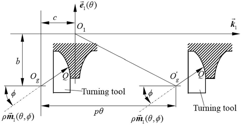
As descried in Section 1, the trajectory surface of the cutting edge of the turning tool forms the worm helical surface. During the worm cutting, a coordinate system is connected to the worm roughcast, and unit vector is along the worm axis. In Figure 2, origin is the middle point of the worm thread length, and point is the intersection of the cutting edge and the worm.
Drawing to account for formation of axial arc tooth profile cylindrical worm.
The cutting edge is assumed to rotate though an angle about axis . The center of the cutting edge moves to along the positive orientation of axis , because the researched worm is right-hand. The length of the vector along axis is , where is helix parameter of the worm.
In the rotation process, unit vectors and become and , respectively.22 The cutting edge rotates around the axis by angle , and a vector from the center of the cutting edge to intersection can be expressed as , where is the radius of the cutting edge.22
Equation and its fundamental forms of worm helicoidal surface
From the geometric construction in Figure 2, the equation of the worm helical surface in is
where , . Thus, the can be represented by
where , , . Symbols and are radial coordinate and axial coordinate of the cutting edge center, respectively.
Assuming that , it is easy to verify that . Thus, the tooth profile of the worm axial section is a segment of circular arc.
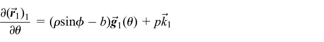
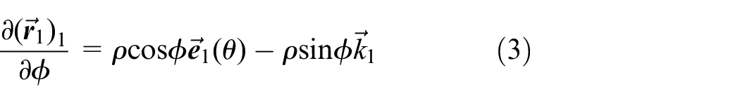
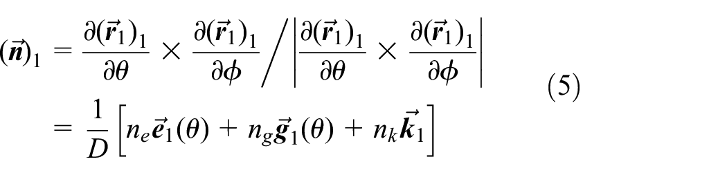
Partial derivatives of are
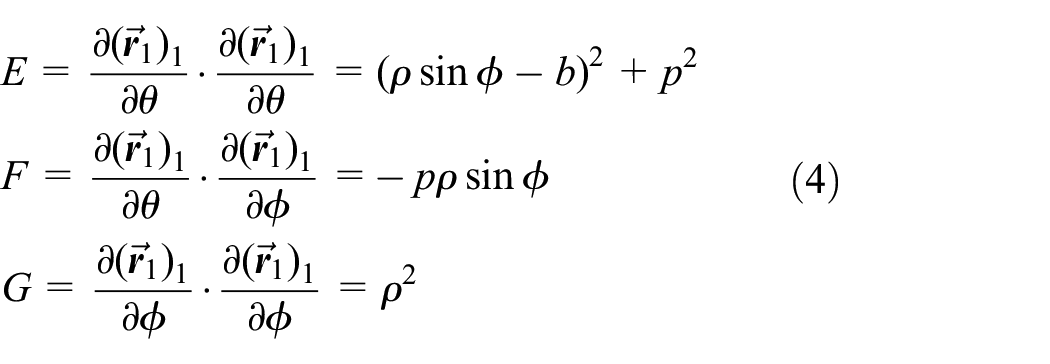
Based on differential geometry,23 the first fundamental quantities of is
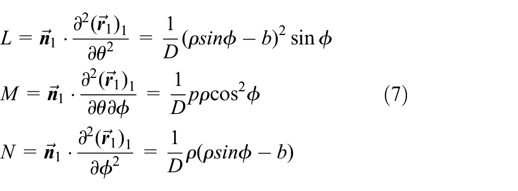
The second partial derivatives of can be obtained in terms of equation (3)
From equations (5) and (6), the second fundamental quantities of is
Frame of worm helical surface and relative geometrical parameters
In equations (4) and (7), neither F nor M is constant . Therefore, orientations of parametric curves at an arbitrary point on are not orthogonal to each other.23 It is necessary to found a moving orthogonal frame for determining geometric parameters of .
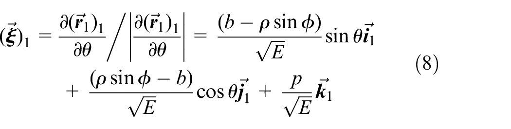
From the first equation in equation (3), unit tangent vector of along the line is
At an arbitrary point M on , a moving orthogonal frame can be established. By the cross product of and , the unit tangent vector can be acquired
where , , .
The is substituted into normal curvature , so the normal curvature along can be obtained as .23
The mean curvature of is
The normal curvature along can be expressed as .23
From equations (4) and (7), the Gaussian curvature of helical surface can be achieved as .23 The is not constant , thus is undevelopable surface.
It can be derived , where is arc length of . From , and the formula derived, it can be obtained
It can be deduced that from equation (11). By definition,24 the geodesic torsion along the line is
Mesh of worm drive
Relative motion and equation of helicoid family
Because the worm drive studied in this paper is a theoretical line contact model, the mating worm gear researched is manufactured by a hob similar to the worm. In Figure 3, static coordinate systems and are connected to the worm and the worm gear, respectively. The shortest distance between origins and is center distance of the worm drive, which is . Unit vectors and are along the worm axis and the worm gear axis respectively, and perpendicular to each other. Unit vector is along the common perpendicular line of and . Rotating coordinate systems and are connected to the worm and the worm gear, respectively. Unit vectors and coincide with and , respectively. The worm revolves around by angle , and the worm gear rotates though angle about . The relation between and is , where is gear ratio. Angular velocities of the worm and the worm gear are toward orientations of axes and , respectively.
Coordinate system and relative motion for meshing of the worm drive.
When the worm revolves around , the helical surface can form a surface family in , whose equation is
where , , . In equation (13), the denotes the rotation transformation matrix and it can be expressed as
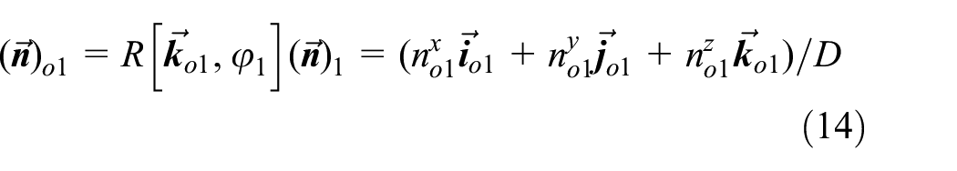
By exploiting , the unit normal vector of can be determined in
where , , .
Not losing the generality, the worm angular velocity can be assumed . Thus, it can be acquired . The relative angular velocity vector of the worm pair in is
Due to , the partial derivative of with respect to is .
The relative velocity at an arbitrary meshing point of the worm pair can be ascertained in
Meshing equation and equation of worm gear tooth face
By definition,22 the meshing equation of the worm pair is
where , , .
The equation of the worm gear tooth surface can be determined in
where , , , and rotation matrixes
, .
Characteristic parameters of worm drive
By definition,22 the meshing limit function can be ascertained
According to matrix rotation method, and can be represented in by
where , , ,
,
, .
The normal vector of instantaneous contact line can be determined in 22
Coefficients and can be figured out from , , , , , , and
where ,
, ,
.
Based on , , and , the curvature interference limit function is
From , , and , induced principal curvature has following form
Generally, if induced principal curvatures are not all positive or all negative, undercutting will occur during the worm pair meshing.
From , , , and , the acute angle between and , called sliding angle, can be figured out as
When the value of is close to , lubrication of the meshing point is excellent.
By means of matrix rotation method, deductions of the worm drive surface equations and characteristic parameters are simplified.
Geometric equations of worm pair section
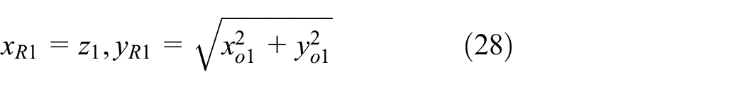
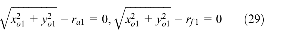
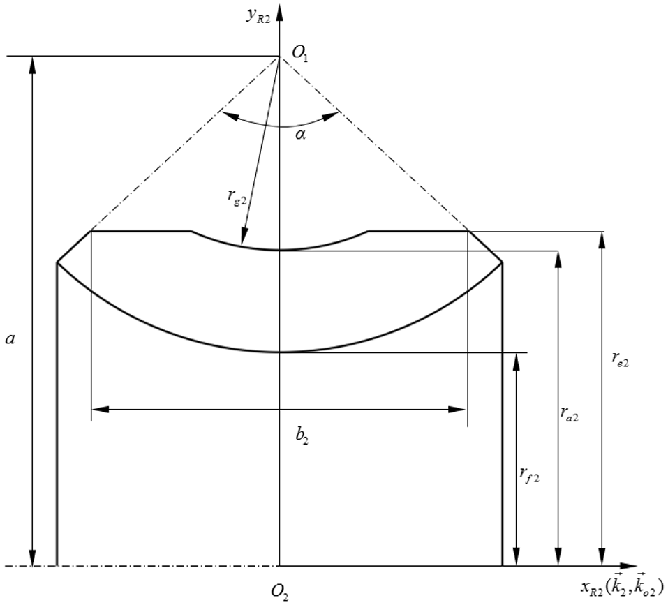
In the worm axial section, a coordinate system is established (Figure 4), and coordinate relations are
Schematic drawing of worm axial section.
In coordinate system , equations of worm addendum and are
where and are radii of top and root circles of worm, respectively.
In the axial section of the worm gear, a coordinate system is established (Figure 5), and coordinate relations are
Schematic drawing of worm gear shaft section.
In coordinate system , equation of gear addendum arc is
where is arc radius of worm gear addendum.
Equations of gear addendum and are
where and are radii of top and root circles of worm gear, respectively.
Equations of gear left and right chamfer are
where and are tooth width angle and tooth width of worm gear, respectively.
Meshing stimulation studies
In this section, the meshing simulation of worm pair is implemented to achieve parameters of meshing points. From achieved parameters, the position of meshing point can be determined. Then, the distribution of contact lines is precisely presented by use of smooth connection meshing points. Moreover, the meshing simulation is the foundation of meshing analysis of the worm drive.
Main parameters of worm drive
In this paper, the numerical simulation is carried out to investigate the meshing property of the worm drive. Main parameters of numerical simulation and their calculation methods are listed in Table 1.
Main parameters of the worm drive.
Description
Symbol and formula
Cases and unit
Center distance
160 (mm)
Modulus
7 (mm)
Reference circle diameter of worm
76 (mm)
Number of worm thread
2
Number of worm gear tooth
33
Gear ratio
16.5
Modification coefficient
0.93
Addendum of the worm
7 (mm)
Dedendum of the worm
8.12 (mm)
Reference circle radius of the worm
38 (mm)
Addendum circle radius of the worm
45 (mm)
Dedendum circle radius of the worm
29.88 (mm)
Tooth width of worm
102.04 (mm)
Helix parameter of the worm
7
Axial tooth profile angle
23 (°)
Axial tooth thickness
8.80 (mm)
Addendum of the worm gear
13.50 (mm)
Dedendum of the worm gear
1.62 (mm)
Reference circle radius of the worm gear
115.5 (mm)
Throat circle radius of the worm gear
129 (mm)
Addendum circle radius of the worm gear
131.8 (mm)
Dedendum circle radius of the worm gear
113.88 (mm)
Throat generate circle radius of the worm gear
31 (mm)
Tooth width of worm gear
55.21 (mm)
Tooth width angle of worm gear
93.17 (°)
Basic parameters of turning tool
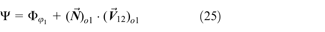
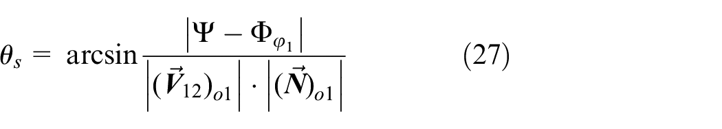
In Figure 6, and can be fixed at addendum and of the worm, respectively.
Basic tooth profile of worm.
Based on and , the first formula of equation (29) can be rewritten as , which can be simplified as . Thus, the can be represented by
It can also be obtained . The range of can be assumed [0, 1]. Thus, the range of can be figured out as . Generally, the is chosen from 5m to 5.5m.1 According to and m = 7 mm, the can be acquired 35 mm. Therefore, parameter can be chosen from 45 to 64.88 mm.
In terms of the worm pair processing principle,2 coordinates of the cutting edge center can be computed as and , respectively. Symbols and are axial profile angle and axial tooth thickness respectively, as shown in Table 1. Thus, the b is determined 51.67 mm probably, which conforms to the range of b. The c is about 36.62 mm.
Computation of conjugate zone of the worm drive
Contact zone DACB of the worm gear surface is drawn in Figure 7. Line DAC is the boundary of the contact zone formed by the worm addendum. In order to reflect the contact zone of the worm, contact zone DACB is projected to the coordinate system as depicted in Figure 8.
Conjugate zone and instantaneous contact lines on the tooth surface of worm gear.
Conjugate zone and instantaneous contact lines in the cross section of worm.
Conjugate zone DACB is divided into DAB and BAC two zones by the meshing limit line in Figures 7 and 8. Therefore, the solution of equation (17) in zone DAB and zone BAC correspond to and , respectively
where , .
By use of equation (35), calculation process of nonlinear equations can be reduced, and meshing points in different zones of the same instantaneous contact line can be determined easily. Moreover, parameters obtained can belong to the same meshing cycle.
Application of elimination method
Meshing points on the meshing limit line are intersections of instantaneous contact lines and line AB. From equations (17) and (19), the formula of with respect to can be obtained as
where , , .
It is obviously that parameter of meshing points on line is a function only about in equation (36). By means of setting values, parameters of meshing points on line AB can be determined. The elimination method obviously improves the operation efficiency of nonlinear equations, which will be widely used in the following.
Computing feature points of conjugate zone
Feature point A is the intersection of the worm addendum and line AB, thus . Substituting into equation (36), value of point A can be fixed. Based on and fixed , of point A can be obtained from equation (17).
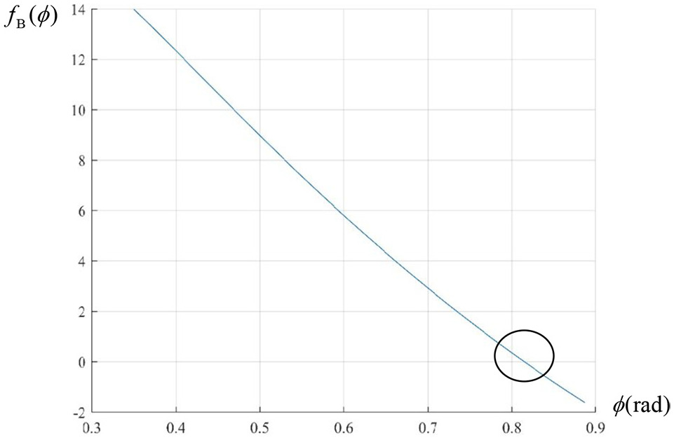
Feature point B is the intersection of the worm gear addendum arc and line AB. It can be obtained and from equations (17) and (19). Based on trigonometric functions obtained, equation (31) and its component expressions, the meshing function of point B can be expressed as
By means of equation (36), the expression (37) can be simplified as a nonlinear function with respect to . The curve can be drawn in the interval , as shown in Figure 9.
The image of curve .
The intersection of and the abscissa axis is near point (0.82, 0). The can be employed as the initial value to determine of point B. Methods to acquire and of point B is similar to those of point A.
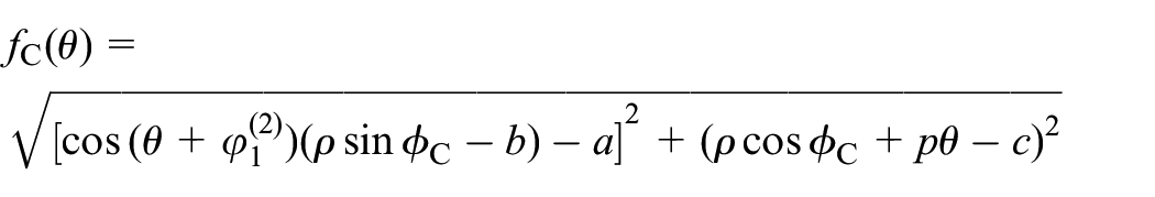
As feature point C is the intersection of the worm addendum and the worm gear right chamfer, . From , the second expression of equation (33) and its component expressions, the nonlinear function of point C is
From graphical method, the of point C can be received. Method to ascertain of point C is similar to point A.
Feature point D is the intersection of the worm addendum and the worm gear addendum, therefore . By using of formula , , and , the first expression of equation (32) can be rewritten as
Methods of determining point D parameters are similar to those of point C.
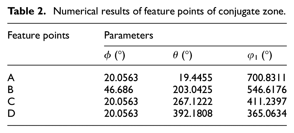
The related parameters of feature points are listed in Table 2.
Numerical results of feature points of conjugate zone.
Feature points
Parameters
ϕ (°)
θ (°)
φ1 (°)
A
20.0563
19.4455
700.8311
B
46.686
203.0425
546.6176
C
20.0563
267.1222
411.2397
D
20.0563
392.1808
365.0634
Determination of meshing points on instantaneous contact line
Based on Table 2, the changing range of rotation angle can be determined. In this range, values of can be assumed. By means of assumed and other conditions, parameters of meshing points can be acquired. Different categories of meshing points solving methods will be introduced as follows.
Determining meshing points on the worm addendum
In Figure 7, meshing points on line DAC are intersections of contact lines and the worm addendum. Taking point of zone DAB as an example, of is the same as . From formula , the meshing function of point can be represented by
Since value of has been assumed, the solution of can be acquired. Parameters of meshing points in zone BAC can be achieved from formula .
Determining meshing points on worm gear addendum
In Figure 7, meshing point, such as on line , is intersection of contact line and the worm gear addendum. With setting , point on line is taken as an example. By means of formula , equation (32) and its component expressions, the system of nonlinear functions of the are
Taking as horizontal axis range, curves of equation (41) are drawn Figure 10. The intersection of and is near the point , so and can be regarded as initial solutions of nonlinear equations.
The image of curves and .
From formula , parameters of meshing points of zone BAC can be acquired. When meshing points are on the worm gear addendum arc, equation (31) is chosen to replace the second formula of equation (41).
Determining general meshing points
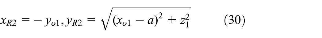
It is necessary to ascertain general meshing points for estimating position of instantaneous contact line accurately. Horizontal coordinates of these points can be calculated by meshing points determined above. Based on the first formula of equation (30), an equation can be established as
Since parameter has been assumed, parameter can be expressed as a function with respect to from equation (42). Then, equation (35) can be rewritten as
From equations (43) and (44), parameters of general meshing points in zone DAB and zone BAC can be obtained, respectively.
Meshing quality of worm drive
In zone BAC, intersections of line (1) and tooth top of the worm pair are not on the worm gear tooth surface. Intersections of line (1)–(4) and line AB are not on the worm gear tooth surface. Only meshing points on the tooth surface are of research significance. Thus, the part of instantaneous contact line on the tooth surface of the worm pair is drawn.
As shown in Figure 7, contact lines near the worm gear addendum fluctuate greatly. Contact lines near the worm gear dedendum fluctuate gently. In Figures 7 and 8, instantaneous contact lines pass through the meshing limit line and enter from one sub contact zone to another. Separated instantaneous contact lines in two sub zones can be called sub contact lines. Rotation angles of two sub contact lines are the same. In this sense, it can be considered that the worm pair is meshed along two sub contact lines at the same time.
Numerical simulation results of the worm drive meshing are listed in Table 3.
Numerical results of meshing simulation.
(a) Induced principal curvature and sliding angel on line (1)–(5).
Points
Meshing parameters
Instantaneous contact lines
(1)
(2)
(3)
(4)
(5)
−0.01771
−0.01525
−0.0133
−0.01193
−0.01112
85.7905
88.5801
81.878
74.0223
65.0643
−0.01646
−0.0127
−0.01092
−0.00792
−0.00613
86.3688
87.7681
81.0481
71.0594
57.2019
/
−0.00779
−0.00897
−0.00475
−0.00324
/
86.3784
80.0668
65.1575
39.8250
/
−0.00850
−0.00522
−0.00324
−0.00230
/
86.2580
74.2678
50.1631
12.5250
/
−0.00930
−0.00683
−0.00451
−0.00256
/
86.0072
76.7242
59.4610
11.7357
/
/
−0.00869
−0.00623
−0.00330
/
/
77.5704
65.2030
29.4560
/
/
/
−0.00849
−0.00443
/
/
/
68.1964
42.7429
/
/
/
/
−0.00616
/
/
/
/
52.3128
/
/
/
/
−0.00878
/
/
/
/
58.2764
(b) Induced principal curvature and sliding angel on line (6)–(10).
Points
Meshing parameters
Instantaneous contact lines
(6)
(7)
(8)
(9)
(10)
−0.01098
−0.01158
−0.01310
−0.01579
−0.02015
55.2550
45.0357
34.9010
25.1696
15.6702
−0.00628
−0.00772
−0.00956
−0.01336
−0.01892
43.7743
33.2209
20.6060
12.7045
8.5989
−0.00416
−0.00610
−0.00872
−0.01284
−0.01878
24.8132
18.1349
5.8082
3.9351
2.0973
−0.00375
−0.00582
−0.00920
−0.01335
−0.01933
3.6771
3.1743
6.9024
5.1035
3.7893
−0.00419
−0.00624
−0.01010
−0.01475
−0.02040
23.6775
9.483
15.5655
13.9993
9.0858
−0.00521
−0.00721
−0.01150
−0.01712
−0.02199
28.3589
21.1144
23.2238
21.9234
14.0199
−0.00687
−0.00874
−0.01362
/
/
39.9665
30.8437
30.0354
/
/
−0.00964
−0.01120
/
/
/
48.3290
38.8271
/
/
/
Induced principal curvature of worm gear tooth surface in meshing process
As already pointed out in Section , values of in Table 3 (a) and (b) are all negative, so curvature interference didn’t happen in the meshing simulation. The absolute value of is smaller in the middle part of instantaneous contact lines and larger on both sides. The absolute value of is smaller near the worm gear reference circle and larger near the worm gear . The maximum absolute value of takes place at the right side of the worm gear approximately, where may be possible to lose efficacy.
Lubricating property of worm pair in meshing process
In Table 3 (a) and (b), values of are between and approximately. Meshing points cover 50% of contact zone on the worm gear tooth surface, whose is between and . It shows that the worm drive has good lubrication performance. The result shows that the is larger on both sides of instantaneous contact lines and smaller in the middle. The is closer 90° near the worm gear addendum and closer 0° near the worm gear dedendum.
As described in Section 3, the lubricating oil film is easy to form on both sides of the worm gear tooth surface, but difficult to form in the middle. The lubrication of the worm gear addendum is better, and that of the worm gear is worse. The minimum value of sliding angle approximately appears on the middle of the worm gear dedendum (Black squares in Figure 7), and there may be hard to form lubricating oil film.
Influence of worm thread number on worm drive
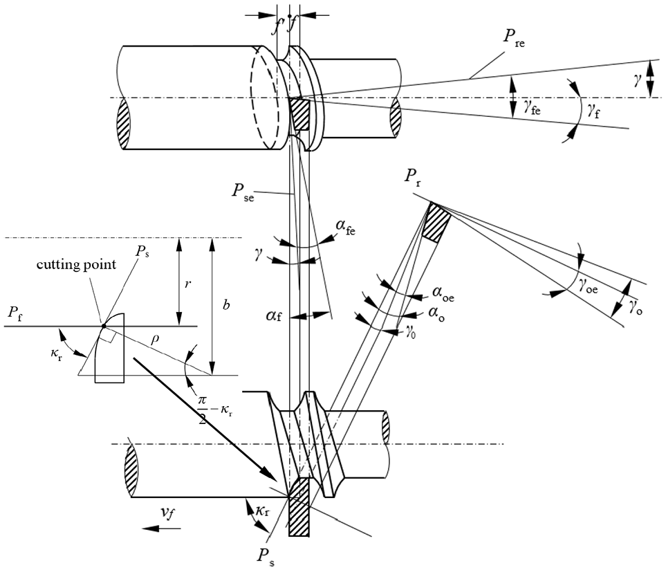
According to previous literatures, the number of the worm thread cannot exceed four, when the worm drive parameters are matched.3,8 Based on the principle of metal cutting,25,26 the geometric construction of turning tool and the worm is established as shown in Figure 11.
Geometric relations of turning tool angles in worm cutting.
In Figure 11, tool reference plane is parallel to the bottom plane of turning tool, which passes through cutting point. Tool cutting edge plane , passes through cutting point, is perpendicular to the . The is working orthogonal rake, and the is tool orthogonal rake. Symbols and are working orthogonal clearance and tool orthogonal clearance, respectively. The assumed working plane of turning tool is , which is the plane of the feed direction .The tool cutting edge angle is the angle between the plane and the plane , which can be represented by .25 The is radial distance of the point on the worm tooth profile.
Considering the feed motion, the working cutting edge plane is tangent to the worm helical surface. The working reference plane is perpendicular to the orientation of resultant cutting speed. Symbols and are working side rake and tool side rake, respectively. The is working side clearance and the is tool side clearance.25 The angle of resultant cutting speed is the lead angle of the worm.
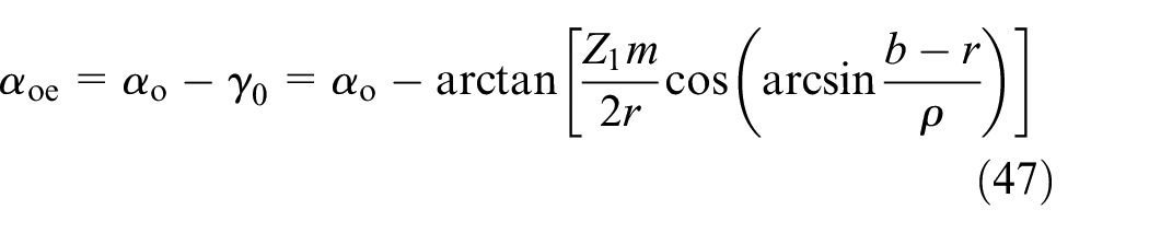
In the working plane, relations of turning tool angles are
In equations (46) and (47), and r are variable, and remaining parameters are consistent with those in Section 5.
Because the worm material is 20CrMnTi, the corresponding turning tool material is cemented carbide, in which content is 30%. Tool orthogonal clearance and tool orthogonal rake are chosen from 10° to 15° and −5° to −15°, respectively.25 In this study, and are assumed.
Variations of working orthogonal angles of the worm with different along the worm tooth profile are shown in Figure 12.
Change of working orthogonal angel along worm tooth profile: (a) working orthogonal clearance and (b) working orthogonal rake.
In Figure 12(a), the increasing leads to the decrease of . When is 5, values of are mostly negative, and the maximum of is 0.1044°. Too small will increase friction between the flank face of turning tool and the tooth surface of the worm. Moreover, if the is negative, the cutting edge strength will be lessened, and the turning tool wear will be accelerated.25,26 In addition, the minimum value of appear at the tooth root of the worm. The lead angles of the worm are 13.19°, 25.11° and 30.36°, corresponding to , 4 and 5 respectively. In fact, undercutting is easy to occur in the worm drive meshing, when .1 Thus, the case of is vetoed.
Because is vetoed, two curves are drawn in Figure 12(b). The increases with the increase of . The working orthogonal wedge angle is the angle between the rake face and the flank surface, which is an index to measure the turning tool. It can be expressed as . In the numerical simulation, values of and are between 60° and 70°, which conform to standard.25
Based on preceding results, the number of worm thread cannot be >4.
Conclusions
This paper minutely presented the meshing theory of the axial arc tooth profile arc cylindrical worm drive. For the worm helical surface with non-orthogonal parametric curve net, a movable orthogonal frame is established to acquire geometrical parameters. The matrix rotation method is fully utilized to optimize deduction and calculation of the worm drive meshing theory.
By means of elimination method, meshing points of different sub contact zones can be obtained in the same meshing cycle easily and the efficiency of solving nonlinear equations can be improved. The distribution of instantaneous contact lines can be precisely determined from obtained meshing points.
The numerical simulation was carried out to study the worm drive. It is easy to form lubricating oil film near the worm gear addendum and both sides of worm gear tooth surface. However, the lubricating oil film near the surface middle of worm gear tooth root forms hardly.
A new method to research the number of the worm thread based on working orthogonal angles is proposed. In simulation results, the working orthogonal clearance decreases with the increasing . If the exceeds 4, the working orthogonal clearance will be negative, which leads wear increasing and service life reducing of the lathe tool. These need to be avoided during the worm machining. Therefore, the maximum of the worm thread is 4.
Footnotes
Appendix
Handling Editor: James Baldwin
Declaration of conflicting interests
The author(s) declared no potential conflicts of interest with respect to the research, authorship, and/or publication of this article.
Funding
The author(s) disclosed receipt of the following financial support for the research, authorship, and/or publication of this article: This study was funded by Open Funds of the Key Laboratory for Metallurgical Equipment and Control of Ministry of Education in Wuhan University of Science and Technology (2018B05 and MECOF2020B03), and the National Natural Science Foundation of China (52075083).
ORCID iD
Yaping Zhao
References
1.
WuHZhangYLinQ, et al. Design of worm drives. Beijing: China Machine Press, 1986.
2.
WangSh.Arc cylindrical worm drive. Tianjin: Tianjin University Press, 1991.
3.
Editorial Committee for Gear Handbook. Gear handbook. 2nd ed.Beijing: China Machine Press, 2004.
4.
ZhuJ, et al. Research on arc tooth worm and worm gear drive. J Taiyuan Inst Technol1963; 1: 1–12.
5.
WuH.Gear meshing theory. Harbin: Harbin Institute of Technology Press, 1979.
6.
HanM.Several problems in design and manufacture of arc tooth cylindrical worm drive. Mining Machine J1981; 9: 24–29.
7.
WangSh.Meshing theory of cylindrical worm with circular profile cut by lathe and worm gear. J Tianjin Univ1980; 2: 15–39.
8.
WangShLiuP.Meshing principle of cylindrical worm drive. Tianjin: Tianjin Science and Technology Press, 1982.