
Abstract
In order to combine the working performance of the motor and the specific requirements for accuracy, a model combining gas bearing with multi-degree-of-freedom (MDOF) motor is invoked. The bearing structure is optimized in terms of lubrication characteristics, which makes the motor life and deflection accuracy have been significantly improved. This kind of special bearing mainly provides a certain supporting force for the motor. Its stability directly affects the output performance of the motor. It should be ensured that the bearing can be used as a stable supporting structure. This paper mainly analyzes the flow field characteristics of this kind of motor, and discusses the stability of the motor by changing the gas film thickness and the motor rotor speed. Firstly, the structure and basic parameters of the air bearing motor are introduced, and the role of the bearing in the motor is described. Then, the film flow field is analyzed theoretically and simulated by finite element software. Finally, the experimental platform of gas bearing stability is built to verify the rationality of finite element analysis. The results provide references for the application of gas bearings in MDOF motors, and provide a direction for the development of precision in MDOF motors.
Introduction
With the current rapid development of artificial intelligence manufacturing, the industry has higher requirements for the stability and precision of machinery and equipment, 1 resulting in traditional multi-degree-of-freedom motor devices that cannot meet the current social needs.2,3 As the product of the new era, the MDOF motor is urgently updated. Lubricating bearings, as an important support component of the motor, began to continuously improve as a breakthrough.
In order to overcome the high friction and low precision of traditional bearings,4,5 many researchers have explored the lubricity of bearings, and have made a variety of choices in lubrication methods. In 1845, Navier and Stoke6,7 proposed the Navier-Stoke equation, which laid a solid foundation for oil film lubrication and promoted the development of hydraulic bearings. It was not until 1854 that French researcher GAH 8 first proposed gas lubrication technology. This proposal is of great significance in the bearing field. It not only broke the embarrassment that traditional bearings cannot adapt to the rapid development of precision instruments, but also produced qualitative lubrication technology leap. The proposal of the gas bearing is needed by the current social development, and has been favored by the manufacturing industry.
Compared with traditional bearings, gas bearings have many advantages such as high speed, accurate accuracy, low power consumption and long life,9–11 and gas bearings are mostly made of air or inert gas as the medium, so there will be no environmental pollution. The problem meets the current social needs of green development. Due to the advantages of structure, gas bearings can adapt to more stringent conditions, especially in the range of −200° to 2000°, which can work normally, which makes gas bearings have a wider application environment. However, gas bearings also have shortcomings. For example, it is easy to damage the outer surface of the bearing during intermittent and low-speed work. Therefore, gas bearings are mostly used in uninterrupted, high-speed and light-load work, which is beneficial to gas bearings. Work stably and efficiently. Since the 1880s, the advantages of gas bearings have gradually been recognized, and exploration has been carried out in the industrial field, especially in some ultra-precision industrial production. After that, gas-lubricated bearings are mainly used in some high-precision machine tools, and the machining accuracy can reach above μm level. In recent years, the representative BELFORG has explored the influence of parameters on the gas bearing. Kuo et al. 12 conducted a feasibility analysis on the gas bearing used in the L-3 stirling cycle refrigerator. At present, the domestic research on gas bearings is still in its infancy, and a set of mature theories on lubrication characteristics has not yet been formed. Therefore, it is necessary to carry out further research on this.
At present, most domestic researchers are studying the design and research of gas bearings, but the research on the characteristics and applications of gas bearings is not perfect,13,14 especially the research applied in the field of multi-degree-of-freedom motors is basically at a blank stage. The combination of gas bearings and multi-degree-of-freedom motors not only expands the application fields of gas bearings, but also provides a new direction for the MDOF motors. This article is based on the research of the flow field characteristics of the air-floating MDOF motor. First, the model of the air-floating MDOF motor is established and the working principle of the motor is analyzed. Secondly, the mathematical model of the hydrostatic gas bearing is derived through the Reynolds equation,15,16 use MATLAB 17 software programming to calculate the influence of different film thickness and different speed on the bearing capacity of gas bearing, and study the feasibility of the bearing; then, the film flow field is analyzed theoretically and simulated by finite element software, 18 and explore the speed distribution and pressure distribution of the bearing under different conditions. Finally, the experimental platform of gas bearing stability is built to verify the rationality of finite element analysis.
Structure and principle analysis
The air-floating MDOF motor combines a MDOF motor with a gas bearing. This structure not only retains the advantages of multi-directional movement, but also reduces the friction generated during the working process of the motor. Rotational movement of the motor rotor is realized by the electromagnetic structure inside the motor.
Air floating MDOF motor structure
Figure 1 shows the structure of an air-floating MDOF motor. In the picture, the air supply pipeline is provided with air pressure from the outside, and the flow field is formed through the orifice, and the flow field provides the bearing capacity. Avoid sliding friction of the motor and support the rotor to run stably.19,20

Schematic diagram of air-floating MDOF motor structure.
Based on the principle of a MDOF motor, a small hole throttle bearing is selected, and its structure is shown in Figure 2. The rotor is in a suspended state when high-pressure gas is introduced from the outside, 21 creating a gap between the stator and the rotor, thereby constitute a gas bearing.

Schematic diagram of gas bearing structure: (a) front section view and (b) top section view.
In Figure 2, the number of orifices is 8, the cone angle of the orifice distribution is θ1, the inlet pressure is Pin, the outlet pressure is Pout, and the thickness of the air gap is h0. In order to ensure that the air pressure around the orifice is stable, a pressure equalizing groove structure is set in each orifice. In order to achieve the small orifice throttling effect, the various parameters of the pressure equalizing groove should meet the following formula (1):

Among them, r0 and r1 are the radius of the equalizing groove and the orifice radius respectively, and h1 is the depth of the equalizing groove.
Air film flow field usually uses air or inert gas as the lubricating medium, 22 and the parameters of different lubricating gases are shown in Table 1. The gas bearing is not only environmentally friendly, but also takes away the heat generated by the motor during the flow of the gas, plays a good role in heat dissipation, and provides a guarantee for the continuous and stable operation of the motor.
Lubricating gas characteristic parameters.

Working principle of motor
The air-floating MDOF motor needs to provide high-pressure gas from the outside before operation, so that the rotor of the motor is suspended relative to the stator, and then the power-on strategy is controlled to complete the motor rotation. The permanent magnet on the rotor generates the electromagnetic force generated by the interaction between the magnetic field and the magnetic field obtained by the energization of the stator coil, the same polarity repels, and the opposite polarity attracts to drive the motor to complete the rotation and deflection movement. Changing the current size and direction of the stator coil can realize the deflection movement of the rotor in all directions. The rotor of the motor uses the structure with an output shaft, and the rotation of the motor is driven by the internal electromagnetic structure. The electromagnetic structure is shown in Figure 3, and the motor movement is realized by changing the power on Strategy of the stator coil.

Schematic diagram of motor electromagnetic structure and permanent magnet flux density: (a) schematic diagram of electromagnetic structure and (b) magnetic flux density.
In Figure 3, a current of plus or minus 10A is applied to the coil, and the strength of the permanent magnet is plus or minus 1.4T, and the arrangement of the magnetic lines of force of the motor is obtained during the electrification process. Among them, the material of the permanent magnet is neodymium iron boron, the stator and rotor structure are both aluminum materials, and the coil is wound on the stator core with copper wire. Among them, Table 2 shows the motor structure parameters.
Structure parameters of air-floating multi-degree-of-freedom motor.

Theoretical analysis of film flow field
Basic condition assumption
As the lubricant of gas bearing, different kinds of gas will have different degrees of influence on the bearing performance. 23 Here we choose air to study. However, due to the particularity of air itself, in the research process, according to the gas lubrication theory, 24 the following assumptions are made for air:
There is a smooth plane between the rotor and the stator;
The inertia of the lubricating gas is negligible;
The internal seal of the bearing is intact;
The gas flow between the stator and the rotor is laminar;
Ignore the influence of gas volume force;
The lubricating gas is Newtonian fluid;
The gas has no relative sliding relative to the bearing surface;
Ignore the temperature change of the gas.
Gas film boundary conditions
When the MDOF motor is working, the air film flow field carries the rotor to rotate at a high speed. At this time, the air film flow field is not only in the convergence zone, but also in the divergence zone. When calculating the gas film flow field, it is necessary to set the boundary conditions for the inlet of the orifice, the outlet of the stator and rotor gap, and the wall of the stator and rotor. When the pressure of the gas bearing reaches the maximum value, the flow field will rupture, leading to the failure of the Reynolds equation. Since the film flow field follows the Reynolds boundary condition,25–27 the internal gas flow should meet:

Where ρ is the density of air, ▽ is the gradient, the scope of φ:

Steady state simulation calculation
The steady-state calculation is to simulate the gas flow in the gas film flow field in the gap between the stator and rotor through simulation software, and calculate the distribution of pressure and velocity inside the bearing. Use CFD software to simulate,28,29 the steps of simulation are shown in Figure 4. Before the finite element analysis, the basic conditions of the model were set. There is a smooth plane between the rotor and the stator, and the influence of roughness on the gas flow is not considered.

Flowchart of steady state simulation of gas film flow field.
Numerical calculation of flow field
During the high-speed operation of the air-floating MDOF motor, the internal flow field produces complex turbulence, which leads to the generation of cyclones near the orifice. In addition, the change of air flow velocity can easily cause the flow field to rupture. 30 According to the gas lubrication theory, the flow field is numerically analyzed, and the spherical coordinate system of the gas bearing is established. 31 Its structure is shown in Figure 5.

Coordinate representation based on spherical coordinate system.
The Navier-Stokes (N-S) equation is used to derive the continuity equation of the flow field in the spherical coordinate system as:
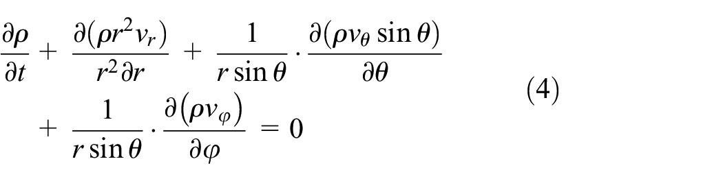
Among them, p is the pressure of the gas at r, θ, φ, and ρ is the density of the gas at r, θ, φ; vr, vθ, and vφ are the velocity components of the gas in the direction of r, θ, and φ, respectively.
After the gas flows out through the orifice, it will flow out in two ways, one from the gap with a flow rate of m1, and the other way into the center of the orifice with a flow rate of m2. When the flow rate reaches a stable level, m2 approaches 0, where:

According to the flow relationship of the flow field, the mass sum after throttling can be obtained as:

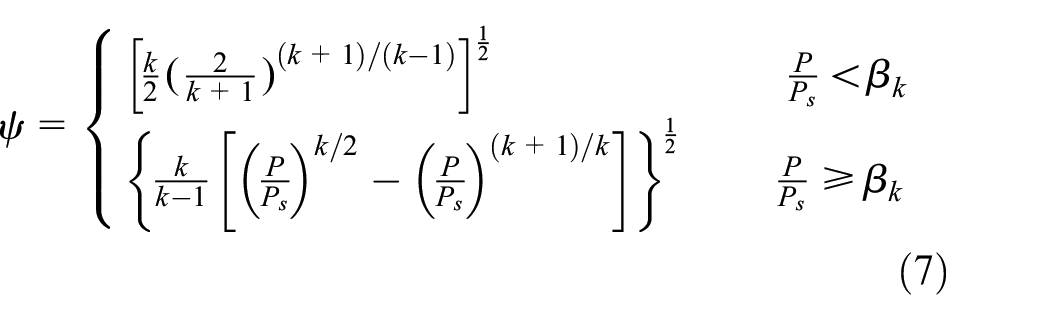
In the formula, βk is the throttling critical pressure ratio, k is the gas specific heat ratio, A is the orifice inlet area, f is the throttling coefficient, generally 0.8, and Ps is the gas supply pressure.
The gas follows the law of conservation of mass in the gas bearing, and the mass flowing in through the orifice is consistent with the mass flowing out of the stator-rotor gap. Simultaneous equations (5) and (6) can be obtained:

Among them, e is the amount of float, η is the gas viscosity, Pa is the air pressure. Through the integral solution of formula (8), the internal pressure of the flow field can be obtained. Since the solution formula is too complicated, it is simplified on the basis of the formula, and the pressure distribution is assumed according to the angle, and then:

Among them, Pd is still an unknown quantity, and Pd = β × Pa is known, so the value of Pd can be obtained by solving β. In order to solve the throttling ratio β, the outflow mass m1, m2 of the throttling orifice is brought into the formula (6), and the relationship between the throttling ratio β and the floating amount e can be obtained as:

Bearing capacity, as an important parameter for measuring gas bearings, cannot be ignored in the test. There is a special relationship between the size of the bearing capacity W and the inlet pressure Pin, which can be further derived under the pressure Pd after throttling. The carrying capacity of the flow field is:

In this paper, the gas bearing structure parameter settings: air supply pressure Pd = 0.4 MPa, outlet pressure 0 MPa. Use analytical method to solve, the function graph of the pressure distribution of the flow field changing with the angle can be derived, as shown in Figure 6. After formula (9) and formula (10) are combined, the change curve of the bearing capacity of the flow field with the floating amount of the rotor is obtained, as shown in Figure 7.

Pressure distribution as a function of angle.

Variation diagram of bearing capacity with rotor floating amount.
Simulation results and analysis
Parameter setting and model establishment
The stable operation of the air-floating MDOF motor is mainly influenced by several factors such as structural parameters, air supply pressure and speed. The structural parameters suitable for the gas bearing are found by adjusting the parameters. The gas bearing simulation parameters in this paper are set as: circumferential eccentricity ε = 0.33, residual error 1e-6, iterative relaxation factor β = 1.5, relative error 1e-3, absolute value error ω = 0.01.
Pressure distribution of gas bearing
Explore the influence of different gas film thickness on pressure distribution by changing internal parameters. The gas film thickness h0 = 25 μm, h0 = 50 μm, and h0 = 75 μm are selected for simulation research. The pressure distribution is shown in Figure 8.
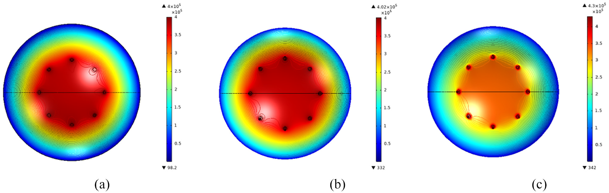
Pressure cloud diagram of gas bearing under different h0: (a) h0 = 25 µm, (b) h0 = 50 µm, and (c) h0 = 75 µm
According to the pressure nephogram of different thickness, the gas pressure around the orifice is the largest. With the increase of the angle, the pressure in the gas bearing decreases until the pressure drops to atmospheric pressure. In addition, with the increase of h0 from 25 μm to 75 μm, the bottom pressure around the orifice is decreasing, which leads to the reduction of bearing capacity.
Velocity distribution of gas bearing
Next, the velocity distribution of the gas bearing is explored, the flow field under different h0 is analyzed by COMSOL, and the corresponding velocity field distribution nephogram is obtained, as shown in Figure 9.

Velocity cloud diagram of flow field under different h0: (a) h0 = 25 µm, (b) h0 = 50 µm, and (c) h0 = 75 µm
According to the velocity cloud diagrams under different h0, the velocity of the entire gas bearing is not very high, only high-speed flow of gas occurs around the eight orifices, and the maximum flow velocity under h0 = 25 μm, h0 = 50 μm, and h0 = 75 μm respectively It is 22.5 m/s, 264 m/s, and 293 m/s. It can be seen that with the continuous increase of h0, its speed is also increasing. In order to see the velocity flow direction inside the bearing more clearly, the simulation analysis of the surrounding part of the orifice in Figure 9 is carried out, and the gas streamline near the small hole is shown in Figure 10.

Velocity section near the orifice: (a) h0 = 25 µm, (b) h0 = 50 µm and (c) h0 = 75 µm.
Cloud diagrams of gas bearing distribution at different speeds
When the motor is running, the flow field inside the gas bearing is relatively complex, so it is necessary to explore the pressure and speed of the bearing at different speeds. Based on the FLUENT software, the pressure and speed distribution nephogram is output, as shown in Figures 11 to 13, and the pressure and speed distribution of the bearing at different speeds are calculated respectively.
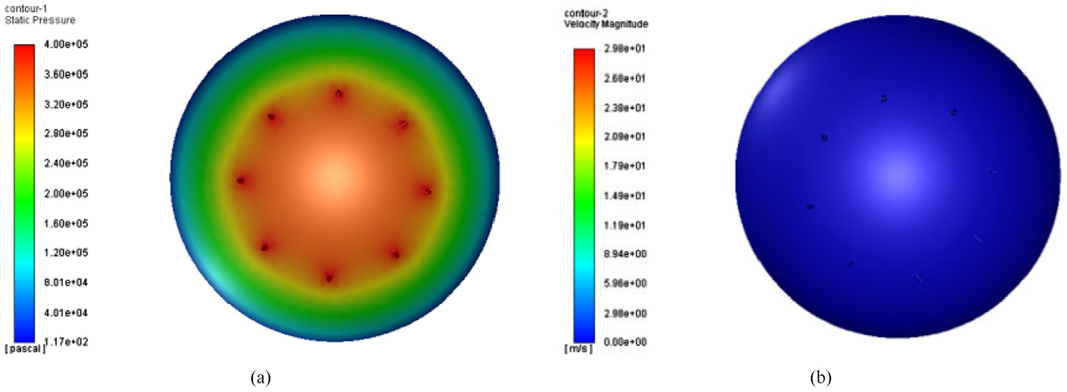
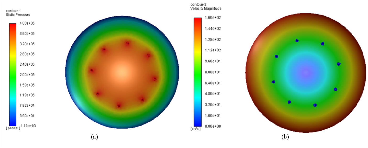
Cloud diagram of flow field at 0 rad/s speed: (a) pressure cloud chart and (b) speed cloud.

Cloud diagram of flow field at 1000 rad/s speed: (a) pressure cloud chart and (b) speed cloud.
Cloud diagram of flow field at 2000 rad/s speed: (a) pressure cloud chart and (b) speed cloud.
When the motor rotor speed is 0 rad/s, there is only static pressure in the air film flow field, but as the rotor speed increases, dynamic pressure effects will appear in the air film flow field at this time, which increases the pressure difference, high pressure domain and low pressure domain The more obvious stratification means that the higher the speed, the dynamic pressure effect generated inside the motor is stronger.
Experiment and result analysis
As an important part of the MDOF motor, the gas bearing supports the movement of the motor rotor, and its stability directly affects the performance and accuracy of the motor. An experimental platform of gas bearing was built to verify the stability of MDOF motor, 32 and a laser vibrometer was used to test the vibration displacement of the rotor. The experimental equipment is shown in Figure 14.

Experimental device: (a) experiment equipment and (b) measuring equipment.
It can be seen in Figure 14, the experimental device contains of two parts, one is experimental equipment, and the other is measuring equipment. The experimental equipment includes multi-degree-of-freedom motors, air compressors, compressed air precision filters, air ducts and other parts. The measurement equipment mainly consists of a laser vibrometer. The vibration change of the rotor represents the stability of the motor. Therefore, an experimental platform can be built to detect the stability of the motor under different air film thicknesses, and then verify the correctness of the theory and simulation analysis. The experimental platform is shown in Figure 15.

Air floatation MDOF motor experimental platform.
The motor rotor performs MDOF deflection movement under electromagnetic action. During the start of the motor, the apex of the rotor performs a spiral movement in the space, taking the apex of the rotor as the Z axis, and making a rotational movement within 30mm downwards, as shown in Figure 16.

The trajectory of the vertex of the rotor output shaft.
During the experiment, the bearing capacity was changed to adjust the thickness of the gas bearing, and then the vibration displacement of the spherical rotor was obtained by the laser vibrometer, and the data was recorded on the computer. The vibration displacement can be obtained by exporting the data recorded on the computer, as shown in Figure 17. The experimentally measured vibration displacements of the gas film flow field thickness at 25, 50, 75 μm are 2.5, 3.3, 4.2 μm, respectively. The experimental results show that the vibration displacement of the spherical rotor increases with the increase of gas film thickness.

Vibration diagram of gas bearing under different gas film thickness: (a) h0 = 25 µm, (b) h0 = 50 µm, and (c) h0 = 75 µm.
Conclusion
Based on the air-floating MDOF motor, the characteristics of the gas bearing are studied, and the modeling analysis is carried out from the perspective of aerodynamics. The internal flow field is calculated by MATLAB, and the influence of the air supply pressure on the bearing performance and the pressure distribution of the bearing under different angles are obtained. By comparing the finite element simulation analysis with the structure of the experimental platform to verify the stability of the air-floating MDOF motor, the following conclusions are drawn:
Optimizing the electromagnetic structure of the motor under the proper conditions is conducive to control accuracy of the motor, increases the working life of the motor, and enables the motor to achieve safe and efficient operation.
The inlet air pressure of the gas bearing is proportional to the bearing performance of the gas bearing. Through the simulation analysis, it is concluded that the gas bearing is suitable for the high-speed rotating motion of the motor. In the process of reducing the gas film thickness, the bearing capacity increases continuously, and the stability of the internal flow field improves continuously.
Based on the experimental platform of gas bearing, the maximum vibration displacement under different gas film thickness is measured by laser vibration meter, and the maximum vibration displacement decreases with the decrease of gas film thickness, which is the same as the conclusion of simulation analysis.
The calculation and simulation analysis in the article provide directions for the optimization design of a motor. It provides data support for the study of the stability of the gas film flow field.
Footnotes
Handling editor: Svalastog J
Declaration of conflicting interests
The author(s) declared no potential conflicts of interest with respect to the research, authorship, and/or publication of this article.
Funding
The author(s) disclosed receipt of the following financial support for the research, authorship, and/or publication of this article: This work is supported by the National Natural Science Foundation of China (No. 51877070, U20A20198, 51577048), the Natural Science Foundation of Hebei Province of China (No. E2018208155), the Talent Engineering Training Support Project of Hebei Province (A201905008), the National Engineering Laboratory of Energy-saving Motor & Control Technique, Anhui University (No. KFKT201901).