
Abstract
A form traveler used in bridge construction has a great influence on the safety of the performance and alignment of bridges. As a cantilever casting segment of a bridge becomes longer and heavier, the traditional form traveler may not meet the strength and stiffness requirements, and there is a risk of collapse. This study has devised a new triangle truss form traveler and investigated the performance based on the Ye-Lang Lake arch bridge in China. Firstly, the numerical models of the form traveler were established to get the strength and stiffness index of the form traveler used for the arch Segment 2. Subsequently, the improvement scheme of the mechanical properties of the form traveler has been proposed. Then the partial refined numerical analysis model of the C-type hook has been established, a finite element model, and a design scheme for improving partial structures of the C-type hook was proposed. Finally, the field load test was carried out to verify the reliability of the new form traveler. The test results show that the improvement of the new form traveler is effective.
Introduction
Cantilever casting is commonly used in building concrete bridges. As an important temporary structure in cantilever casting, the form traveler can be divided into the rear fulcrum form traveler and the front fulcrum one based on the stress mode.1–5 There are triangles, and diamonds form travelers, which are applied to the cantilever casting construction of concrete bridges. The front form traveler is more applied to the cantilever casting construction of concrete cable-stayed bridges, and during the process of each cantilever casting of the segmented main beam, the bearing capability of the form traveler is improved through the tension of different grades.
In southern China, a large number of arch bridges have been built in recent years as a result of the mountains and valleys, and the cantilever casting combined with the cable-stayed construction has emerged as the times require. Compared with traditional cable hoisting, cantilever casting does not need the prefabricated site, with better integrity and less maintenance in the later stage. 6 It has been found out that in recent years, China has built ten concrete arch bridges such as Baishagou No. 1 Bridge,7,8 Xinmidi Bridge9–11 and Fuyu Bridge in Sichuan, Mupeng Bridge, 12 Mati River Bridge 13 and Ye-Lang Lake Bridge14–17 in Guizhou, Longxi Wujiang Bridge and the multiple-tracked Peiling Wujiang Bridge in Chongqing, Shatuo Bridge in Yanhe, Guizhou and Jiming Three Provinces Bridge in Sichuan.
As an important temporary structure of cantilever cast arch bridges, the form traveler has a significant influence on the carrying capacity of the concrete arch bridge.18–22 The safety of the form traveler and the arch must be ensured before the two sides of the arch are connected. Ye-Lang Lake Bridge is currently the largest spanned reinforced concrete arch bridge of cantilever casting with a single cell and box. As the cantilever cast segment is long and heavy, and the bars tend to be stressed out, and the end of the cantilever tends to be overly bent. It cannot meet the requirements for large-segmented cantilever casting. Therefore, a new type of form traveler is in urgent need, whose structure will be improved in engineering application.
Cantilever-Casting is a common construction method of the long-span concrete bridge. The rationality of traveler structure in cantilever-casting structure has a significant impact on the construction speed and quality. Therefore, the accurate analysis and improvement of traveler structure have significant engineering value. Structural optimization includes performance improvement and weight reduction, which is particularly important in aircraft structure.23–28 This paper, based on the new form traveler adopted in the cantilever construction of Ye-Lang Lake Bridge with a main span of 210 m, aims to improve its structural details and verifies its working performance by carrying out the load test, thus provides useful references for the cantilever casting of similar long-span arch bridges in the future.
Engineering survey
General situation of the bridge
Ye-Lang Lake Bridge is currently the largest spanned cantilever cast reinforced concrete arch bridge with a single cell and box in China. It spans 210 m with a net rise span ratio of 1/5 and an arch axis coefficient m of 1.67. The general layout of the bridge is shown in Figure 1. The arch ring adopts the section of a single cell and box with a width of 7.0 m and a height of 3.5 m, as shown in Figure 2. The thickness of the top and bottom plates of the cast-in-place section of the arch foot support gradually changes from 80 to 40 cm, and that of the web plate changes from 80 to 50 cm, while the top and bottom plates of other segments are 40 cm and the web plates are 5 cm. The arch foot supports of Segment 1 are cast-in-place while Segment 2–14 is cantilever cast with the form traveler. The closure section of the rigid skeleton in the middle span is 24.65 m long, with the rigid skeleton wrapped with concrete.

The general layout of the bridge.

The section of the arch foot (units: m).
Structural arrangement of the new triangle truss type form traveler
Currently, there is no cantilever cast reinforced concrete arch bridge of such a large scale in China, so there are no precedents to refer. As the segment is long and heavy in the cantilever casting construction of the arch bridge,29–34 a new type of triangle truss form traveler (hereinafter referred to as the form traveler) is proposed. The form traveler mainly consists of the bearing system of the main truss, the stay cable, the C-type hook, and the walking track. The C-type hook is connected to both sides of the main truss in the middle. The top of the hook is connected with the walking device, while the walking device is located on the walking track at the top of the segmental cast-in-place arch ring. During the cantilever casting, the upper part of the C-type hook does not bear the structural stress; however, as the worker walks, the C-type hook will walk along the walking track direction and thus will bear the stress. Four stay cables are used to connect both sides of the connecting plates on the C-type hook with the pull seats on the side of the front basket and that of the rear basket of the bearing system of the main truss. An anti-rolling device is provided for the rear basket, and a suspender is arranged on the truss bearing system to lift the load-bearing anchor. The upper and lower chord members of the form traveler are composed of trusses made of section steel, which are connected to the C-type hook shaft through the steel sling. The C-type hook consists of a box-shaped section of the welded steel plate, and during the concrete casting of the arch box, the dead weight of the form traveler and the wet weight of the concrete is assumed by the anchor suspender.24–32 The main performance parameters of the new form traveler are shown in Table 1.
Main performance parameters of the form traveler.

Compared with the traditional form traveler in cantilever cast reinforced concrete arch bridge, the new form traveler (as shown in Figure 3) has many advantages, such as high strength and stiffness. Because the horizontal check device is simple in form and has less damage to the baseboard of the arch ring, and the reaction roller device is simply structured and clearly stressed, the form traveler can be adjusted efficiently. The anti-offset device is simple and efficient. The anchor suspender is anchored at the top formwork of the cantilever end of the arch ring, and the partial mechanical performance of the arch ring segment has been improved.
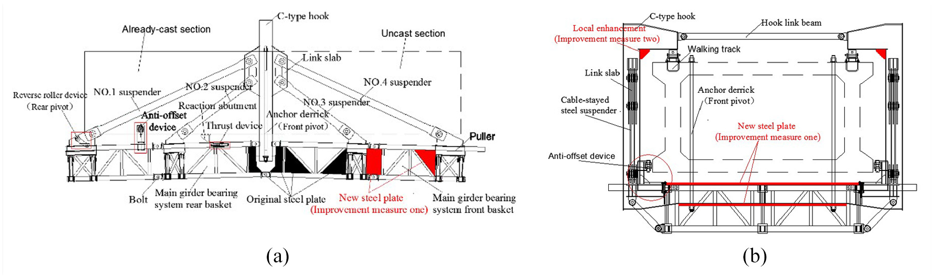
(a) The front view of the form traveler at the site and (b) the side view of the form traveler at the site.
Analysis of mechanical properties of the form traveler and improvement of partial structures
To ensure the safety and reliability of the form traveler of the preliminary design in the cantilever casting construction and the internal force and the alignment of the arch rings meet the design requirements after the cables are released, analyses on the mechanical performance of the form traveler during the cantilever cast construction of the arch ring of Segment 2 (Segment 2 is the longest and heaviest) and on the mechanical performance of the C-type hook when the form traveler travels asymmetrically (under the three typical working conditions) are subsequently carried out, and finally, the improvement scheme of the local structural design of the form traveler is formulated.
Analysis of the form traveler under cantilever casting construction and improvement of its structural details
Establishment of the finite element model
The finite element software Midas/Civil was used to build the analysis model of the form traveler. The beam element is applied to simulating all the members of the form traveler, and the plate element strengthening the form traveler is used to simulate the steel plate. The unit weight of Q345 steel is corrected to 106.5 kN/m3 based on the difference between the weight in the finite element model and that of the form traveler, and the elastic modulus is taken as 2.06 × 10⁵ N/mm2. The specific simulation mode and numerical values of each load considered in the calculation are as shown in Table 2. In terms of boundary conditions, all degrees of freedom are constrained at the anchor bolt of the front fulcrum of the form traveler, and degrees of freedom of three linear displacements are constrained at the rear fulcrum. The hinges between the member bars of the form traveler girders are simulated by releasing the constraint of the bar end. The anchor of the stay cable is simulated with the rigid arm. The lower anchors are connected with, the lower beams by a rigid arm. The finite element model and the load of the form traveler are shown in Figure 4 and Table 2, respectively.
Load of form traveler.

“−” represents the vertical and download direction of the load

The finite element model of the form traveler.
According to “Technical Specifications for Construction of Highway Bridges and Culverts”. The analysis includes the stress and deformation of the structure. The structural stress should be less than 210 MPa, and the maximum deformation of the hanging basket should be less than 20 mm. In the strength checking calculation, all the above loads are combined;35–39 in the stiffness checking calculation, only loads of the wet weight of the concrete, the diaphragm, and the form traveler formwork need to be combined. Based on the allowable stress, all load combination coefficients are 1, as shown in Table 3.
Load combination of two calculations.

Strength and stiffness calculation and analysis of the form traveler of the preliminary design
The calculation results of the strength and stiffness of the form traveler during the concrete casting of Segment 2, as shown in Figure 5. To facilitate the display, the component in Figure 5 is zoomed. Therefore, the components are connected and not separated, as shown in Figure 5. The stress and displacement results are summarized in Table 4.
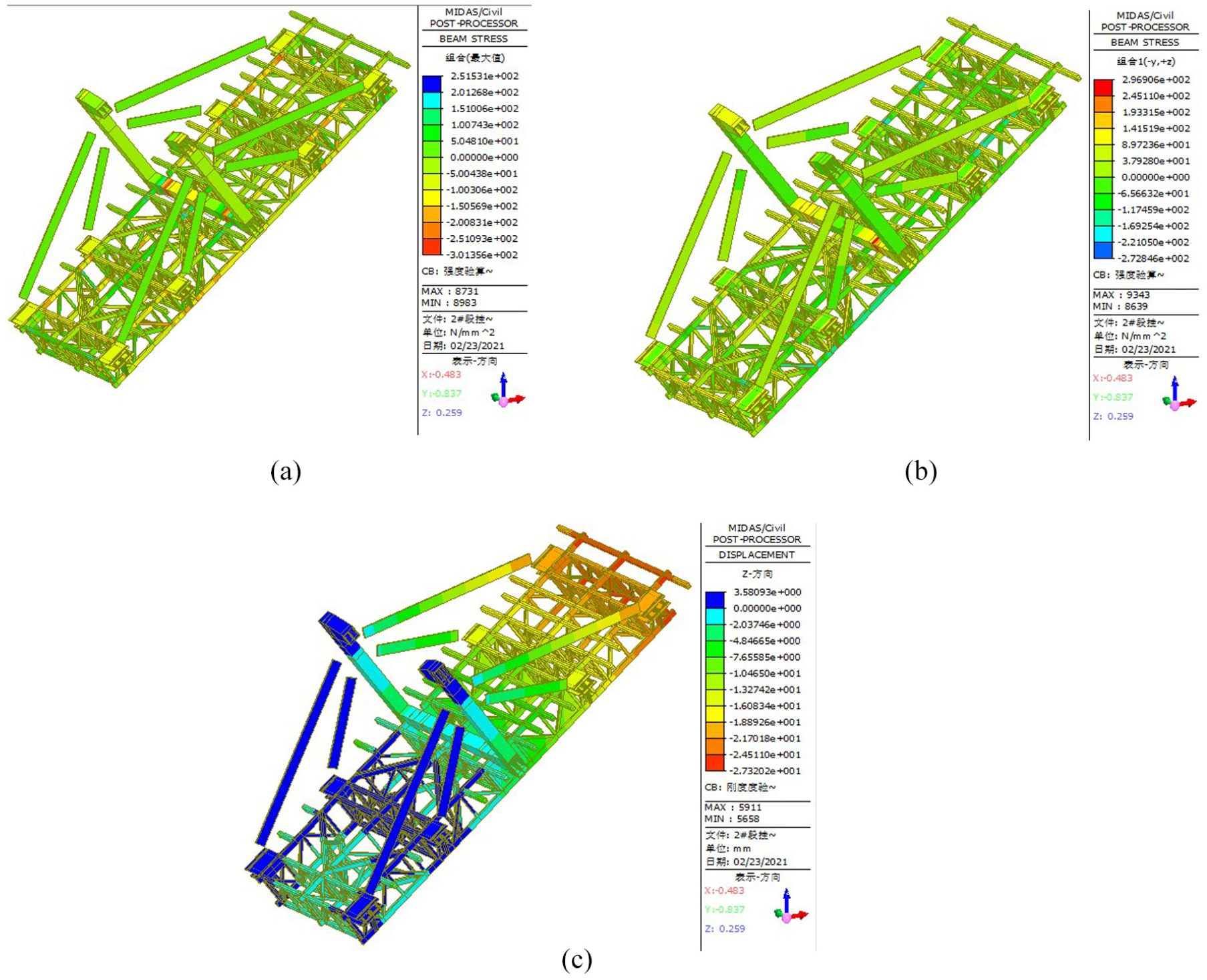
(a) Combined pressure stress of the form traveler when casting 2# segment (units: MPa), (b) combined tensile stress of the form traveler when casting 2# segment (units: MPa), and (c) vertical displacement of the form traveler.
Stress and displacement of the form traveler when casting 2# segment.

Based on Table 4, the maximum combined pressure stress of the form traveler is 301.4 MPa in the cantilever casting of the arch ring of Segment 2. The maximum combined tensile stress near the temporary anchorage point of the C-type hook beam is 296.9 MPa, exceeding the allowable stress value of 210 MPa for Q345 steel. Hence it is suggested the combined stress be not exceeding 240 MPa. Meanwhile, the combined pressure stress of the top chord near the anchor bar of the stay cable at the front end of the form traveler and that of the upper chord near the anchor bar at the rear end of the form traveler are also slightly too large. The maximum deflection of the form traveler is 24.5 mm, slightly larger than the required value 20 mm of “Technical Specifications for Construction of Highway Bridges and Culverts”.
The combined pressure stress of the top chord near the anchor bar of the stay cable at the front and rear ends of the form traveler is relatively large, which is related to the finite element simulation of boundary conditions. In the actual structure of the form traveler, the cable is connected with the main truss of the form traveler through the cantilever steel box, the reinforcing chord, and the gusset plate, so the stresses are complex. In the Midas/Civil simulation, the members are connected together by rigid connections (as shown in Figure 6). As a result, the stress of the reinforced chord (the upper and lower chords of 20 groups) cannot be truly reflected, and the internal force is transferred to the connecting chord, thus resulting in the higher combined pressure stress of the upper chord near the anchor of the cable.

Partial enlarged drawing of the basket boundary simulation.
Considering the pressure stress of partial members of the form traveler exceeds the allowable value of the steel, it is necessary to improve the partial structure of the form traveler.40–44 Here are some proposed improvement measures.
Partial reinforcement measures for the form traveler
Here are two methods adopted to improve the structural details.
A 16-mm steel plate should be welded where the stress of the truss chord is large to enhance the partial strength of the form traveler and improve the partial pressure stress, as shown in Figure 3(a).
A 10-mm steel plate is welded on the top of the bottom beam and the baseboard of the C-type hook, as shown in Figure 3(b).
Analysis of strength and stiffness after improving the structural details of the form traveler
After the above two strengthening measures are taken, the strength and stiffness of the form traveler are calculated. The results of stress and displacement are listed in Figure 7.

(a) Combined pressure stress of the form traveler when casting 2# segment (units: MPa), (b) combined tensile stress of the form traveler when casting 2# segment (units: MPa), and (c) vertical displacement of the form traveler when casting 2# segment (units: mm).
It can be seen from Figure 7 that the stress of the C-type hook beam of the form traveler has been improved, and the maximum combined pressure stress has been reduced from 301.4 to 206.1 MPa, and the maximum combined tensile stress has been reduced from 296.9 to 193.8 MPa. The maximum combined pressure stress is 246.5 MPa, which occurs at the upper edge of the transverse truss of the rear anchor, where the maximum combined tensile stress also occurs, which is 242.4 MPa. The maximum deflection of the form traveler has been reduced from 2.54 cm to 21 mm. As the partial strength of the form traveler has been strengthened by welding steel plates, the maximum combined pressure stress has been greatly reduced, and the maximum combined stress is slightly larger than the allowable stress value of 240 MPa, but the difference between the two is within the allowable difference of 5%.
Analysis of the form traveler under its walking condition and improvement of the structural details
To further investigate the stress of the C-type hook when the movement of one side is checked while the other side moves normally, ANSYS is adopted to establish the precision numerical model. Also, the load boundary conditions are introduced to ensure the validity of the analysis model.
Establishment of the finite element model
The C-type hooks are made of 20 and 12 mm steel plates. The width and length values of the plates are larger than the thickness value, so they can be simulated with SHELL 181. To avoid larger errors in the calculation caused by mesh deformity, the geometric model adopts mapped meshing. Based on the partial mesh of the C-type hook in Figure 8(a) that the model mesh is of high quality.

(a) Partial mesh quality and (b) displacement boundary conditions
To simulate the condition in which the movement of the hanging arm on one side of the C-type hook is checked while the other hanging arm on the other side moves normally, the degree of freedom of the hanging arm on one side is constrained along the track, and that of the other side is forced to move a given distance (10, 20, 30 mm) along the track. In the meantime, in view of the actual working state of the hook, the vertical and horizontal degrees of freedom of the joints connected with the track on both sides of the hook are constrained. The displacement boundary conditions are shown in 8(b).
The C-type hook is the most important stress transferring component of the form traveler in that when the form traveler moves forward, the weight of the whole form traveler is transferred to the C-type hook through the sling and finally transferred to the track anchored on the arch ring. Since the model of the C-type hook has no sling or the supporting truss of the lower formwork, it’s necessary to add extra load to simulate the sling and the supporting truss of the lower formwork to ensure the validity and authenticity of the model analysis. ANSYS is adapted to the whole model of the form traveler to calculate the axial stress of the sling.
Analysis of the strength and stiffness of the form traveler of the preliminary design
Based on the above finite element model, the nephogram of the first principal tensile stress of the form traveler structure activated by its self-weight load is shown in Figure 9. The computed results show that the maximum tensile stress of the hook is 189.2 MPa, which is less than the yield stress and design stress of Q345 steel.

(a) The first principal tensile stress nephogram of the C-type hook when it moves normally (units: MPa) and (b) the first principal tensile stress nephogram of the C-type hook when moving normally (units: MPa).
When the form traveler moves, the movement of the hanging arm on one side is checked, and the hanging arm on the other side moves forward 30 mm. The nephogram of the first principal tensile stress of the structure is shown in Figure 10. The computed results show that the maximum principal tensile stress of the hook is 246 MPa, which is 57 MPa higher than the normal working stress of the form traveler but still less than the yield stress and design stress of Q345 steel.
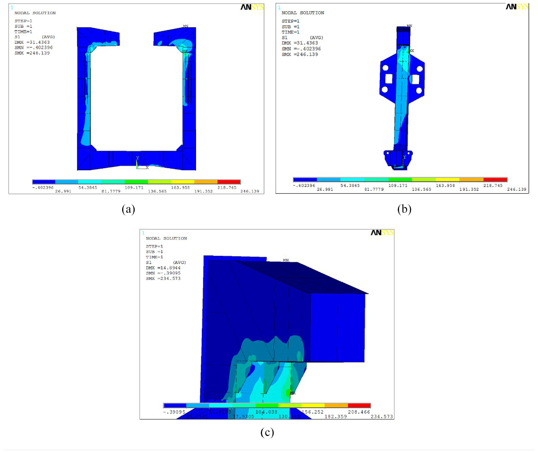
(a) The first principal tensile stress nephogram of the C-type hook when moves abnormally (units: MPa), (b) the first principal tensile stress nephogram of the C-type hook when moving abnormally (units: MPa), and (c) the first principal tensile stress nephogram of partial structures when moving abnormally (units: MPa).
To study in detail the stress state of the form traveler when one hanging arm is checked while the other moves forward for different distances, the stress state of the structure is analyzed when the displacement difference of the two hanging arms along the track direction is 10, 20, and 30 mm respectively, and the maximum principal tensile stresses of the C-type hook under different working conditions are summarized in Table 5.
The main tensile stress of the structure with different displacement differences of hanging arms on both sides along the track direction (units: MPa).

Partial strengthening measures for the C-type hook of the form traveler
To further reduce the main tensile stress and improve the safety of the hanging arm, transverse steel plates of 5 mm are used to connect the stiffening plates arranged separately by the C-type hook of the preliminary design to form a closed stiffening haunch (as shown in Figure 11). It is found that the stress on the C-type hook has been greatly reduced after the closed stiffening haunch is formed, as shown in Table 5.

(a) Stiffener at the C-type hook in the preliminary design and (b) Stiffener at the C-type hook in the improved design.
Some understandings of the new triangle truss form traveler
Be it Midas/Civil or ANSYS, the whole modeling and calculation of the form traveler show that the stress of some components of the form traveler tends to be large. Therefore, in the segmental cantilever cast of the whole arch ring, the temporary construction load should be strictly controlled to ensure construction safety.
Based on the calculation and analysis, it is found that the diagonal bracing (as shown in Figure 3(b)) located near the sling and connecting the upper and lower chord members has a significant influence on the stress of the top chord members of the form traveler. Therefore, the machine precision of the diagonal bracing should be ensured by strictly controlling the size of the hinge joint so that it can firmly connect the upper and lower chord members and transfer stresses.
The components loaded with large stress of the form traveler should be checked and monitored more carefully to ensure the safety of the form traveler itself.
To improve the stress ability of the bottom plates of the arch box and prevent the bottom plates from cracking, the anchor suspender must be anchored on the top plates of the arch box, and in this way, the stress can be loaded on the whole arch ring.
Preload test of the form traveler on site
Purpose and procedures of the load test of the form traveler
To ensure the safety and quality of the segmental cantilever casting of the arch ring, the preload test of the form traveler must be carried out to make sure the quality of the form traveler meets the design requirements and verify the rationality of the improved form traveler. At the same time, the preload test can prevent the inelastic deformation of the form traveler and help obtain the elastic deformation parameters of the form traveler, which provides a theoretical reference for the cantilever casting of the arch bridge. The specific procedures of the preload test are as follows:
The vertical anchor cable is set on the original ground, and the steel strand is applied to pull the form traveler. After the form traveler has been assembled, the preload test will be carried out on Segment 2.
After Segment 1 has been cast, four vertical anchor cables (6φj15.24 mm steel strand for a single anchor cable) will be established at the plane position in Figure 12(a). The cables are 17 and 19 mm long, and the part of the anchor in the rock is less than 10 mm. A 50 cm × 50 cm × 30 cm concrete base is cast on the original ground, and a 50 cm × 50 cm × 30 cm I-shaped steel box is installed on the top of the base. The anchor cable is being strained on the I-shaped box, and the cable hole is grouted.
When the cable of Segment 1 is being strained, its support cast-in-place is removed and the form traveler is assembled (except for the bottom formwork). Two 2I40b I-shaped steel boxes are installed on the top of the cantilever end of the form traveler as the ant-strain longitudinal beam, and four leveling steel boxes are welded at the corresponding positions on the top of the longitudinal beam, as shown in Figure 12(b).
Install the vertical steel bundle. One single vertical steel bundle is made of 4φj15.24-mm steel strands. The lower end is anchored on the steel box on the top surface of the base, while the upper end is strained, anchored on the leveling steel box on the longitudinal beam of the top surface of the form traveler.
The weight of Segment 2 is 1886 KN, and each vertical steel bundle is loaded in the order of 30% ∼70%∼100%∼110%∼120%. Every time the load is added to another load grade, observe the sedimentation value of the front end of the form traveler and check whether there is any abnormality at the connection between various structures of the form traveler. 10 min later, record the data; 25 min later, record the data again. Next, renew the strain to the next level and when it is 120%, check again whether the form traveler is abnormal or not. Observe the sedimentation value of the front end of the form traveler, wait for 60 min, and after making sure there is no abnormality, start unloading.

(a) Site layout of the hanging basket load test scheme and (b) site layout of the form traveler load test scheme.
Comparison of measured results and theoretical results of the form traveler displacement
The maximum displacement is observed to be located in the middle of the first transverse cross-link. The measured and theoretical displacement values are compared, as shown in Figure 13.

Comparison of theoretical and measured displacements at the measured maximum displacement.
According to Figure 13, the maximum difference between the measured and the theoretical values at the maximum displacement is 9 mm, which occurs when the loading is 120%. The error in Figure 13 is mainly caused by the initial displacement in the measurement. After deducting the initial displacement of the test results, the numerical results are in good agreement with the test results. The overall carrying capacity of the form traveler can meet the design requirements. The preliminary design and partial improvement of the form traveler are reasonable, which can be applied to the cantilever cast-in-place construction of a large segment.
Conclusion
This study has devised a new form traveler used in bridge construction and numerically and experimentally investigated its performance. The main findings are summarized as follows.
The maximum combined stress of some components of the form traveler exceeds the specified allowable value when cantilever casting the arch ring of Segment 2. Both the upper chord near the anchor of the cable-stayed sling at the front end of the form traveler and the bottom chord near the anchor of the stay cable at the rear end of the form traveler exceed the allowable stress value of Q345 steel with the maximum deflection of 24.5 mm. Because the stiffness of the form traveler is insufficient, it is necessary to improve the partial structures of the form traveler. The 10-mm steel plates can be welded on the top and bottom plates of the cross beam under the C-type hook, and 16-mm steel plates can be added between the members with higher stress. The comparative analysis result shows that, after the above improvement measures have been taken, in the form traveler cantilever casting of the arch ring of Segment 2, the maximum pressure stress has been reduced from 301.4 to 246.5 MPa, and the maximum deformation has been reduced from 24.5 to 21 mm.
When the form traveler moves forward, the maximum principal tensile stress of the structure is 246.1 MPa when one hanging arm is checked while the other one moves forward 30 mm, which exceeds the normal working stress of the form traveler. Transverse steel plates of 5 mm are connected with the No. 5 stiffening plates arranged separately by the C-type hook in the preliminary design to form a closed stiffening haunch. The maximum principal tensile stress of the structure has been reduced to 187.8 MPa, and the safety of the form traveler has been significantly improved.
By way of the preload test of the hanging test, the displacement changing tendency during the loading process of the form traveler is obtained. The overall changing tendency of the measured displacements is in a close agreement with that of theoretical calculations. The overall bearing capacity of the form traveler meets the design requirements, and the improvement of the form traveler is effective.
Ye-Lang Lake Bridge was opened to traffic successfully on August 31st, 2018. The maximum difference between the measured value and the theoretical value of the arch ring alignment is only 25 mm, which meets the specified requirements. The arch rings are well aligned. Meanwhile, the shape and the internal force of the completed bridge also meet the design requirements, which further proves that the improvement of the form traveler design is reasonable and can meet the construction requirements of the cantilever cast-in-place arch of large segments. This paper can provide useful references for similar engineering projects in the future.
Footnotes
Acknowledgements
This work was supported by the National key R & D Program (2017YCF0806007), National Science Fund for Distinguished Young Scholars (51425801), Chongqing Technology Innovation, and application demonstration project (cstc2018jscxmszdx0084), and Graduate Education Innovation Fund Project of Chongqing Jiaotong University (2019B0107).
Handling editor: James Baldwin
Declaration of conflicting interests
The author(s) declared no potential conflicts of interest with respect to the research, authorship, and/or publication of this article.
Funding
The author(s) received no financial support for the research, authorship, and/or publication of this article.