
Abstract
The shaft bearing is the key component of water pump and its fatigue failure results in the abnormal operation of the system. However, the failure mechanisms of bearing are still unclear. In this paper, the failure analysis on the engine water pump shaft bearing was carried out by using the measurement of material composition and properties, observation of macro and micro morphologies, and theoretical analysis of fatigue failure. The wear behavior and failure mechanisms were clarified, and the prevention measures was further proposed. The bearing failure reflected from the fracture of bearing cage and serious wear of roller and mandrel. The wear behavior of the mandrel originated from the surface fatigue, and the failure was attributed to the large radial deflection load. Further, the decreased weight of impeller and shaft connector and the increased bearing thickness were recommended to improve the bearing operation.
Introduction
Since its small size, compact structure, and low cost, the water pump shaft bearing has been widely used in the automobile engines. The water pump is driven by crank shaft of the engine to circulate the coolant through water jackets dissipating heat under the operated pressure, which promotes the transformation of kinetic energy into pressure energy.1,2 Due to the superior specific load moving ability, the bearings have been extensively utilized in the system of water pump to reduce the friction between contacted surfaces, and have been considered as the major components of water pump. 3 As the connection between the rotor and support, the safety and stability of bearings are the key to ensure the normal operation of water pump. With the development of science and technology, the increasingly harsh conditions of the bearing require higher and higher performance, and the bearing failure inevitably results in the major engineering equipment losses, economic losses, and casualties.4,5 Therefore, it is of significance to understand the failure mechanism of the pump shaft bearing during operation in order to prevent long-term breakdowns or/and catastrophic failures.
Generally, the bearing failure was attributed to the interacted failure factors of bearing, including human factors, equipment factors, material, processing methods and qualities, and service condition. 6 A large number of failure analysis cases in the previous references confirmed that the bearing life was obviously influenced by the material quality (large inclusions, defects), heat treatment quality,7,8 stress concentration, 9 unreasonable design, 10 improper process, 11 environmental factors,12–14 machined surface quality15–18, and overload.19–21 To the best of our knowledge, there is no systematic and effective failure analysis method for the water pump shaft bearing. Therefore, it is crucial to find a scientific analysis method to obtain the failure mechanisms of the bearing.
Herein, we proposed a detailed failure analysis method for the water pump shaft bearing, and the main analysis was sequentially summarized as follows. Firstly, the relevant background information of failed bearing, including bearing operation records, failed bearings and debris, bearing manufacturing process and service status (the use of bearings and daily maintenance), and the bearing materials based on the relevant quality inspection report and related standards was collected. Secondly, the damage morphology of failed bearing was observed and the tests of lubricating oil performance and bearing technology were carried out. Then, the chemical composition, hardness, and microstructures were also determined. Finally, the wear mechanisms and failure mode of the bearing, based on the furrow, cracks, peeling off, and defects, were comprehensively clarified. In this paper, according to the above methods, the diversified failure analysis was conducted to elucidate the fatigue failure mechanisms of the water pump shaft bearing, as well as the proposition of prevention strategy.
Experimental methods
Pump shaft bearing
Automobile engine pump shaft bearing is a simplified double bearing system, as shown in Figure 1. The left side near the impeller is the deep groove ball bearing, while the right power end is cylindrical roller bearing. The structure is suitable for high load and impact load. There is no inner ring about the two supporting bearings, and the rolling body is directly mounted on the shaft. The shaft is generally treated by surface induction hardening. The depth of hardened layer is 1.8–2.5 mm, and other items are required to comply with relevant requirements of GB/T 5617-2005.
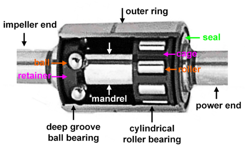
Sectional view of the integral bearing structure of automobile engine pump shaft.
The failed bearing installed on the water pump shaft of the automobile engine, after running mileage of about 600,000 km, was dismantled for failure analysis. The bearing with type of WR2552185 has abnormal vibration and noise, and the materials are GCr15. The macroscopic morphology is shown in Figure 2. The outer ring of the two supporting bearings is made into a whole. Seals are used on both sides of the ring to form the composite parts of the bearing.

(a) Macroscopic morphology of pump shaft bearing, (b) side view, and (c) top view of pump shaft bearing without pump housing.
Chemical composition
The chemical composition of mandrel sample and rollers was determined by X-ray spectrometry, using SPECTOR-M9 direct-reading spectrometer according to GB/T18254-2016 standard. Through the comparison with standard sample, the average value was obtained by measuring three times.
Hardness measurement
The Rockwell hardness was measured using a Rockwell hardness tester. A load of 150 kg and a dwell time of 30 s were conducted on the mandrel surface of the spindle complying with the GB/T34891-2017 standard. Three points were chosen at intervals of 120° in the circumferential direction, and each point was measured three times to obtain the average value. To measure the micro hardness distribution of the mandrel, HTV-1000 Vickers hardness tester was used under a load of 1 kg.
Microstructural characterization
The metallographic sample were grinded with increasing SiC paper (80–2000 grade), then mechanically polished with 0.5 μm diamond particle spray, followed by being etched with a solution containing HNO3 (4 ml) +C2H5OH (96 ml). The microstructures in the specimen was observed by DMI5000M optical microscopy. For SEM analysis, the surface of the sample was first ultrasonically cleaned. The worn surface morphologies of the mandrel were imaged on the JSM6380LV scanning electron microscope (SEM) operated at 20 kV. Elemental analysis of filtered debris was performed by an equipped INCA7582 spectrum of energy dispersive (EDS).
Results
Morphological analysis of bearing
The pump bearing was intact without obvious damage, and the bearing seal was unbroken, as shown in Figure 2. After disassembly, the overall bearing consisted of the deep groove ball bearing on the impeller side and the cylinder roller bearing on the power side (Figure 3(a)). To clarify the failure mechanism of pump bearing, the macroscopic morphologies of bearing groove, steel ball, and bearing retainer were examined separately. The core shaft groove surface and steel ball surface were bright without no obvious running traces, as shown in Figure 3(b) and (c). In addition, there was no obvious damage on the cage (Figure 3(d)). Note that the lubricant of deep groove ball bearings was dark brown and bright without no obvious discoloration. Therefore, it was concluded that the deep groove ball bearing on the impeller side operated normally.

Disassembly morphology of pump shaft bearing: (a) integral bearing, (b) groove of deep groove ball bearing, (c) bearing ball, and (d) bearing cage.
The components of the cylinder roller bearing including outer ring, cylindrical roller, and bearing cage were disassembled and examined respectively, as well as the mandrel surface. The raceway color of outer ring was dark gray with local circumferential wear traces and pits, as shown in Figure 4(a). There were many circumferential wear traces on the surface of the raceway of mandrel, which were distributed along the circumference and accounted for about 2/3 of the whole circumference (Figure 4(b)). Among the seven rollers, surface color was gray-black and there were evenly distributed pits and wear traces. At the same time, the end faces of cylindrical rollers were bright without obvious damage (Figure 4(c)). The cage was seriously damaged and unable to be completely spliced together, and there were more fracture parts on the both ends and less damage to the longitudinal girder (Figure 4(d)). Therefore, it was inferred that the damage of bearing cage occurred first at the both ends. Consequently, the vibration and noise abnormalities of the water pump shaft bearing were mainly attributed to the failure of the cylinder roller bearing on the power side. Therefore, the following failure analysis mainly focused on the hardness distribution, crack propagation, and fatigue behavior of the cylindrical roller bearing.

Disassembly morphology of cylindrical roller bearing: (a) wear trace on outer raceway surface, (b) wear marks on mandrel surface, (c) damage morphology of roller surface, and (d) fracture morphology of bearing cage.
Composition analysis and hardness distribution
The chemical composition of mandrel and rollers on the power side were measured and listed in Table 1. The results showed that the contents of C, Si, Mn, and Cr in mandrel were higher than that in rollers. The chemical compositions were within the range of standard ingredients, complying with the relevant provisions of GB/T18254-2016.
Chemical composition of failed and standard mandrel and roller.

The measured hardness on the failed roller and mandrel surfaces were given in Table 2, as well as the standard hardness according to the standard GB/T34891-2017. The surface hardness was approximately to be 64 HRC, and the hardness and uniformity of the tested parts meet the requirements of the standard.
Surface hardness of failed bearing parts and standard requirements.

Filtered metal debris without pollution
It was worth noting that the lubricating grease of cylindrical roller bearing parts was seriously oxidized and turned black. After cleaning and filtering with clean gasoline, only a small amount of metal debris was found to be free of foreign bodies (Figure 5(a)). Through the energy spectrum analysis, the main chemical elements were detected to be Fe, Cr, O without other abnormal elements, as shown in Figure 5(b). Hence, it was concluded that the lubricant was clean and pollution-free.

Morphology of filtered metal debris (a) and SEM images of the debris and corresponding energy spectrum analysis (b).
Discussion
Crack formation and propagation
The metallographic analysis of cylindrical roller with severe wear shown that there were a bright secondary quenching layer and a high temperature tempering layer on the surface of cylindrical roller with severe wear and tear. The maximum depth was about 0.20 mm, among them, the depth of secondary quenching layer was 0.07 mm (Figure 6). According to GB/T34891-2017 standard, the microstructure contains fine martensite, a small amount of residual austenite and carbide, and the reticulated carbide is characterized with single granular and aggregated chains, which meets the requirements of relevant standards.

Surface metallographic structure of worn cylindrical roller.
The microstructure of the mandrel hardened layer was characterized, as shown in Figure 7. There were also an obvious secondary quenching layer and a high temperature tempering layer on the surface of local quenching layer (Figure 7(a)). According to GB/T5617-2005 standard, the microstructure in the mandrel consists of acicular martensite in the hardened layer and lath martensite in the internal matrix. Some micro-cracks emerged in the secondary quenching layer, and the larger cracks propagated through the tempering layer to the internal matrix (Figure 7(b)). Hence, it could be concluded that high temperature generated on the surface of the bearing during operation, resulting in burning of the surfaces. Besides, the crack originated from the surface and was the source of surface fatigue.

(a) Crack morphology and (b) corresponding magnification in the secondary quenching and tempering layers of the worn mandrel.
The micro hardness distribution of the mandrel was shown in Figure 8. It was divided into three different regions, representing the microstructural distribution. The mandrel in regions I and II was treated by induction quenching, and the depth of hardened layer was measured to be 1.86 mm, which met the standard requirements. The region III represented the matrix of mandrel. In addition, the secondary tempering, resulting from the excessive surface temperature of the mandrel during operation, promoted the generation of burning surface with decreased hardness at the quenched mandrel surface. It was reflected from the region I in Figure 8 and the thickness of burning layer was measured to be about 0.22 mm, which was consistent with the metallographic characterization in Figure 8.

Gradient curve of microhardness distribution of the worn mandrel.
Wear behavior and mechanism
Figure 9 shows the uneven worn surface of the failed mandrel at two randomly selected locations. The wear characteristics, including furrow, peeling off, and micro-cracks, were mainly found on the worn surface. During the bearing operation, the friction and wear occurred on the contact surface. The wear produced debris and wear particles (Figure 9(c) and (f)) with high hardness, which could not be discharged in time and remained on the contact surface. The abrasive dust rubbed repeatedly between the contact surfaces and played a role of ploughing, resulting in the generation of furrow, as shown in Figure 9(a) and (d). Due to the eccentric loading, the local stress at the surface increased. The high temperature generated in the friction process led to the increased temperature of the contact surface and the formation of secondary quenching and tempering layers. Additionally, the abrasion resulted in the uneven surface and the stress concentration at the local contact points, which caused the surface peeling and micro-crack, Figure 9(b) and (e). As the bearings continued to roll, the micro-cracks propagated and produced the peeling off. Consequently, it was concluded that the bearing had surface origin fatigue failure after rolling.

SEM morphologies of the worn surfaces of mandrel at two random locations: (a–c) location 1 and enlarged view of the dashed black region and (d–f) location 2 and magnification of the dashed black region.
Fatigue failure and prevention
The pump bearing was characterized by one end of the belt as a power input, driving the other end of the blade rotation to achieve drainage purposes. From the above analysis, the cylindrical roller bearing at the power end had serious wear and a lot of surface cracks. And, the burn layer and superficial peeling emerged on the surfaces of cylindrical roller and mandrel. Especially, the wear marks of the mandrel are found along the circumferential direction and accounted for about two thirds of the ring track, indicating the abnormal operation of cylindrical roller.
For the fatigue failure of bearing, some factors influencing bearing life were summarized and excluded. Firstly, no foreign body was found in the lubricating grease of cylindrical roller bearing, and the grease contaminated by foreign matters was invalid. Secondly, the hardness and quenching and tempering microstructures of the bearing mandrel and cylindrical roller complied with related standards, and the substandard heat treatment quality was ruled out. Although the local burn layer (secondary quenching layer and high temperature tempering layer) on the surface of the roller and the mandrel was not excluded from the insufficient lubrication, it would not lead to the breakage of the dynamic end cage.
Herein, the roller and mandrel were considered as two elastic cylinders with curved radius of R1 and R2, and lied in contact with parallel axes, as shown in Figure 10. The maximum pressure (P0) could be expressed by the following equation from Hertzian theory 22 :
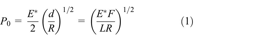
with

Schematic diagram of the paralleled contact between roller and mandrel.
The radial load of pump shaft bearing mainly consisted of tension of driving belt and the weights of water pump impeller and shaft connector. Hence, we proposed the following preventive measures, including reducing the weight of water pump impeller and shaft connector, increasing the bearing thickness to improve the radial bearing capacity and so on. The bearing thickness represented the mandrel diameter. As the thickness increased, the mandrel diameter (R) in equation (1) increased, resulting in the decreased contact force. On the other hand, the increased mandrel diameter promoted the reduced the bending deformation of the mandrel and prevented the reduction of length, further decreasing the contact force.
Conclusions
The fatigue failure analysis of the engine water pump shaft bearing was conducted by using the chemical composition detection, hardness distribution testing, wear morphological characterization, and theoretical analysis. The wear behavior and failure mechanism of the engine water pump shaft bearing was in-detail elucidated, and the subsequent prevention measures were further proposed. The main conclusions were summarized as follows.
The abnormal operation of the water pump shaft bearing was mainly attributed to the failure of the cylinder roller bearing on the power side, rather than the deep groove ball bearing on the impeller side. Excluding the composition, hardness, and microstructures complying with the standard requirements, the fracture of bearing cage and serious wear of roller and mandrel mainly resulted in the bearing failure.
The wear characteristics on the failed mandrel surface, including furrow, peeling off, and micro-cracks, confirmed the rolling bearing having surface origin fatigue failure.
The abnormally large radial force from bearing deflection promoted the abnormal operation, the fracture of bearing cage, serious burning, and wear of bearing roller and mandrel, accompanied by the abnormal vibration and noise. In addition, the decreased weight of water pump impeller and shaft connector, and the increased bearing thickness were proposed to prevent the fatigue failure.
Footnotes
Handling Editor: Assunta Andreozzi
Declaration of conflicting interests
The author(s) declared no potential conflicts of interest with respect to the research, authorship, and/or publication of this article.
Funding
The author(s) disclosed receipt of the following financial support for the research, authorship, and/or publication of this article: The authors would like to acknowledge the financial support from the National Key Research and Development Program (2018YFB2000302, 2016FYB030010), National Natural Science Foundation of China (51904187) and Open Foundation of National United Engineering Laboratory for Advanced Bearing Tribology, Henan University of Science and Technology (201901).