
Abstract
Herein, we synthesized a new polyethylene glycol (PEG)-based solid polymer electrolyte containing a rare earth oxide, CeO2, using mechanical metallurgy to prepare an encapsulation bonding material for MEMS. The effects of CeO2 content (0–15 wt.%) on the anodic bonding properties of the composites were investigated. Samples were analyzed and characterized by alternating current impedance spectroscopy, X-ray diffraction, scanning electron microscopy, differential scanning calorimetry, tensile strength tests, and anodic bonding experiments. CeO2 reduced the crystallinity of the material, promoted ion migration, increased the conductivity, increased the peak current of the bonding process, and increased the tensile strength. The maximum bonding efficiency and optimal bonding layer were obtained at 8 wt% CeO2. This study expands the applications of solid polymer electrolytes as encapsulation bonding materials.
Introduction
Encapsulation is an important part of the production process of microelectromechanical systems (MEMS) because it affects the service life of MEMS. Anodic bonding is a low-temperature bonding process that uses electrostatic forces to form a permanent connection between material interfaces via a chemical reaction. The anodic bonding of MEMS devices produces small thermal stress and almost zero pollution and has a high encapsulation quality, making it increasingly used for MEMS device encapsulation.1–3
As a common anodic bonding material, glass-ceramics and silicon cannot meet the needs of various types of sensor packaging, fast Ion conductor films with good ionic conductivity and flexibility have become one of the new research objects. In previous research work, we found that polyethylene oxide (PEO) complexed with lithium perchlorate can be anodically bonded to metal, while the polyethylene glycol (PEG) and PEO have similar anodic bonding properties and are better than PEO. The PEG is a solid electrolyte that has a good spatial coordination structure and a high density of electronic groups.4,5 It is composed of flexible polyether segments, and its ethoxy groups easily undergo conversions, easily forms a uniform system that provides a good scaffold for making modifications to improve its bonding performance.
Inorganic particles can improve the mechanical properties of solid electrolyte matrixes.6–10 They can also improve the ion conductivity, widen the electrochemical stability window, and increase the interfacial stability. The unsaturated 3d and 4f shells of rare earth elements have a variety of physical and chemical properties. CeO2 is a common non-magnetic rare earth oxide with a stable structure that does not undergo phase changes below its softening temperature.11–14
Few reports have explored the use of encapsulation bonding materials with PEG matrixes. This study expands the application of rare earth element-modified PEG-based solid electrolytes for bonding encapsulation of MEMS.
Experimental
Sample preparation
PEG (Mw = 4000 Da, purity > 99.6%, granularity < 70 µm), LiClO4 (purity > 99.6%, granularity < 50 µm), and CeO2 (purity > 99.4%, granularity < 500 nm) were placed in a vacuum drying oven at 50, 100, and 130°C for 24 h. Then, all mixed powders were placed in agate jars, using anhydrous ethanol as abrader and agar balls as a milling medium (diameter: 8, 5, 3 mm; ratio: 1:1:1). Ball milling parameters were: a speed of 280 rpm, a milling time of 10 h, and a ball-to-material ratio of 8:1. After milling, the powdered materials were dried and sieved to obtain a fine powder. The resulting homogeneous mixed powder was heated to the melting temperature of the composites, and the resulting slurry-like mixture (PEG)10LiClO4–x%CeO2 was pressed in a cylindrical mold cavity into a round sheet with a diameter of 25 mm and a thickness of 3 or 5 mm. Finally, the material was placed in an oven.15,16
Sample characterization
(PEG)10LiClO4–x%CeO2 was sandwiched between two stainless steel electrode (SS), assembled into SS//(PEG)10LiClO4–x%CeO2//SS, and the AC impedance spectroscopy was performed using a Solartron 1260A and 1287A electrochemical interface system. SS//(PEG)10LiClO4–x%CeO2//SS samples were placed in the controllable thermostat, using a frequency range of 0.1–1 MHz and a test temperature range of 15–100°C.
A P10-10 electrohydraulic servo fatigue testing machine was used to test the mechanical properties of the samples at room temperature. The equipment specification was 10 kN, and the accuracy grade was 0.5.
For the yield strength tests, 10 mm × 10 mm × 5 mm samples were placed horizontally on the equipment load plane. The initial position of the upper and lower jaws of a tensile tester was adjusted, and the pressure rate was set to 0.02 mm/s.
For the tensile strength tests, the samples were cut to 10 mm × 10 mm × 2 mm. Due to the small size of the sample, they were difficult to process into a standard test piece. First, the top and bottom surfaces of the sample were attached to an electrolyte material and aluminum foil surface, respectively. Then, AB glue is applied to the sample and glued to the upper and lower jaws of the tensile tester. The sample was kept horizontally bonded during the bonding process. After allowing the AB glue to dry for 15 min, the tensile test starts until the interface is broken, at a stretching rate of 0.02 mm/s.
Anodic bonding experiment
The aluminum foil (bonding material) was immersed in 50 g/L NaOH solution to remove the surface oxide film, and then residual surface impurities were removed with acetone.17,18 When acetone had completely evaporated, the aluminum was overlapped with the prepared (PEG)10LiClO4–x%CeO2. Then, the aluminum was connected to the anode, and (PEG)10LiClO4–x%CeO2 was connected to the cathode, and the pressure was adjusted after closing the bonding furnace, as shown in Figure 1. The bonding experiments were performed under nitrogen protection.19,20 During the experiment, the bonding temperature, bonding current, and bond voltage were recorded as a function of time.

The anodic bonding schematic.
Results and discussion
Surface characterization
The surface characteristics of the material are an important part of its anodic bonding performance. Understanding the surface microstructure characteristics will help understand the ion transport characteristics and principles of polymer electrolytes. In Figure 2, at 3 wt.% CeO2, the surface of the electrolyte matrix was messy and the crystal was more obvious and irregular. When the content of CeO2 was 5 wt.%, CeO2 has an effect on the matrix structure, the crystalline particle size was smaller. But the material still showed a higher crystallinity, with a low amorphous content on the surface. When the content of CeO2 was 8 wt.%, the surface characteristics of the solid electrolyte changed obviously, the disordered crystal structure became ordered, and the size of the crystal decreased obviously, such a feature is more conducive to the movement of ions within the crystal. Continuing to add CeO2 to 12 wt.%, a large number of crystals were re-condensed on the surface of the matrix, which might be caused by the agglomeration of CeO2, indicating that excessive CeO2 could not reduce the crystallinity of the material and hinder the transmission of ions. 21

The SEM image of (PEG)10LiClO4-x%CeO2 surface: (a) x = 3, (b) x = 5, (c) x = 8, and (d) x = 12.
X-ray diffraction (XRD) analysis
Figure 3 shows the XRD patterns of (PEG)10LiClO4–x%CeO2 with different CeO2 contents. The polymeric system has two prominent diffraction peaks near 19° and 23°, indicating a high crystallinity. When the CeO2 content was increased to 8 wt.%, the diffraction peak intensity at 19° and 23° decreased significantly; however, as the CeO2 content was further increased, these peaks did not change, and the relative intensity of the characteristic diffraction peaks of CeO2 began to increase. This PEG crystallization occurred in two stages: nucleation and growth, the crystalline growth of the polymer chain segments used thermal motion as energy.22,23 CeO2 disrupted the ordered structure of the PEG molecular chains, disturbing the segments and, thereby, reducing the total energy provided by the thermal motion of the segments. As a result, there was insufficient energy for crystal nucleus growth, and the whole system failed to completely crystallize. When appropriate amount of CeO2 acts on PEG matrix, they can effectively inhibit PEG crystallization. The Li+ transmission required to produce an amorphous area will increase, and the transmission channels are extended, which facilitates anodic bonding; however, excess CeO2 particles may form agglomerates and impede the migration of Li+. Although a portion of the CeO2 particles will serve as nucleation sites, the Li+ transmission required to produce an amorphous area will be reduced which will restrict migration and decrease the anodic bonding efficiency.

The XRD pattern of (PEG)10LiClO4-x%CeO2: (a) (PEG)10LiClO4, (b) (PEG)10LiClO4-5wt.%CeO2, (c) (PEG)10LiClO4-8wt.%CeO2, and (d) (PEG)10LiClO4-12wt.%CeO2.
AC impedance
Figure 4 shows the AC impedance spectra obtained for different CeO2 contents at room temperature. When the CeO2 content was low, the high-frequency region appears as an asymmetrically compressed semicircle, which represents the body resistance and geometry capacitance of (PEG)10LiClO4–x%CeO2. The low-frequency region is a characteristic line that reflects the degree of ion diffusion. When the CeO2 content reached 8 wt.%, the AC impedance spectrum changed significantly, and the high-frequency semicircle was not observed, mainly because of the very steep slope of the line. The low-frequency region reflects the corresponding double-layer capacitor charge and discharge process. This curve (8 wt.%) indicates the best electrical conductivity and minimal body resistance. When the content of CeO2 reached 12 wt.%, the body resistance began to increase, and the conductivity of the composite began to decline.

The AC impedance spectra of (PEG)10LiClO4-x%CeO2 at room temperature.
As shown in Table 1, the ion conductivity increased with the CeO2 content, reaching a maximum at 8 wt.% CeO2. At this time, the ionic conductivity of the electrolyte at room temperature was an order of magnitude higher than the material without CeO2. When the CeO2 content exceeded this value, the ion conductivity began to decline.
The ionic conductivity of (PEG)10LiClO4-x%CeO2 at room temperature.
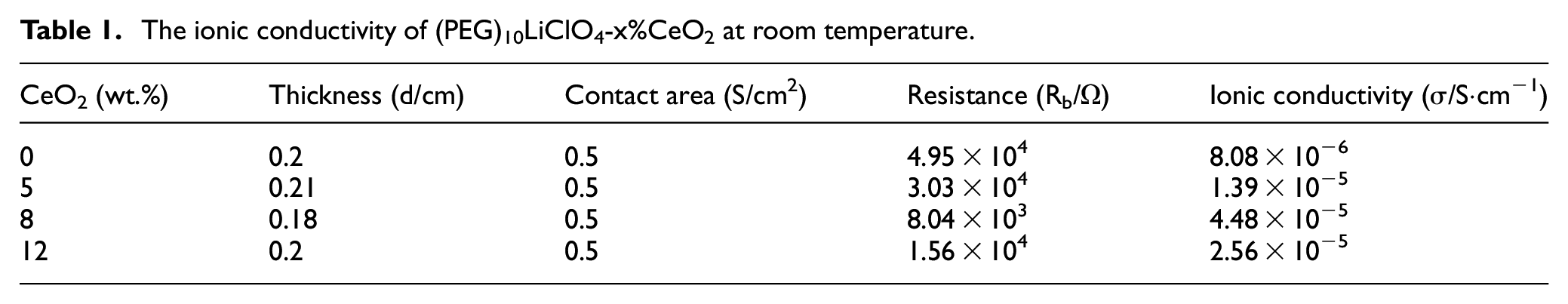
These results indicate that Ce4+ destroys the coordination between PEG and Li+, leading to the formation of (-CH2-CH2-O-Ce-)n when the (PEG)10LiClO4 system is modified with CeO2 nanoparticles. However, the coordination of PEG and Ce4+ hindered the crystallization of PEG, and, thus, more Li+ was released and coordinated with PEG. Anodic bonding requires the free movement of ions at the bonding interface to form a bonding layer to connect two materials; therefore, introducing CeO2 facilitated anodic bonding.
Thermal analysis
PEG is a long, linear polymer chain, with (CH2-CH2-O) n repeat units, with hydroxyl groups at both ends. It easily crystallizes with a large phase change enthalpy, and its thermodynamic properties are very complex.
Figure 5 shows the TGA curves of the three samples. All three samples had only a small weight loss before 260°C due to a small amount of adsorbed water and residual impurity decomposition. There is a significant weight loss of (PEG)10LiClO4 around 260°C, and its residue after thermal decomposition was almost zero. When CeO2 was added, the thermal decomposition temperature of (PEG)10LiClO4-8wt.%CeO2 increased to 310°C, indicating that CeO2 improved the thermal stability of the complex. The thermal decomposition residues of the composite solid electrolytes were 4.5% and 7.8%, which corresponded to the amount of added CeO2 (5%, 8%).

The TGA curve of solid polymer electrolyte (PEG)10LiClO4-x%CeO2.
Figure 6 is the DSC curve of the prepared sample, and Table 2 is the corresponding thermodynamic properties. According to the measured melting enthalpy (ΔHm) and sample content, the sample crystallinity was calculated. The standard melting enthalpy ΔH*m of PEG is 203 J/g. The crystallinity of pure PEG was high at room temperature. The internal structure of PEG changed after adding LiClO4, which also changed its crystallinity. As shown in Table 2, the crystallinity of (PEG)10LiClO4 was 47.71%. When CeO2 was added, the molecular structure was changed because CeO2 interacted with the ethoxy groups in PEG, which reduced the intermolecular interactions and inhibited crystallization. When the CeO2 content was increased to 8 wt.% the crystallinity of the composite decreased to 34.72%, which is 12.99% lower than that of the material without CeO2. The decreased crystallinity is helpful for ion transport and for improving the anodic bonding performance.

The DSC curve of solid polymer electrolyte (PEG)10LiClO4-x%CeO2.
The thermodynamic properties of the solid polymer electrolyte (PEG)10LiClO4-x%CeO2.

Mechanical properties analysis
PEG contains long, regular, and easily broken polymer segments. The anodic bonding process requires materials with good mechanical properties to ensure bonding quality. Table 3 shows that the tensile strength of the polymer was proportional to the CeO2 content. At 15 wt.% CeO2, the tensile strength was 54.18 MPa, which is 12.04 MPa higher than that of (PEG)10LiClO4.
The yield strength of (PEG)10LiClO4-x%CeO2 at room temperature.

CeO2 diffused into the interior of PEG through a long ball-milling process and became embedded between the weak molecular chains and strengthened the material. When the system was subjected to external forces, CeO2 dispersed and transferred external forces, which weakened the stress concentration of the molecular chains when subjected to external forces. This improved the mechanical properties and dimensional stability of the entire system. When the CeO2 content exceeded 8 wt.%, the crosslinking effect of CeO2 and PEG was weakened, but the crystallization was increased. The improved mechanical properties of the material may be due to the higher crystallinity of the system.
Anodic bonding current-time curves
Figure 7 shows the current-time curves during the anodic bonding process (80°C, 800 V, 20 MPa). 16 At the beginning of the bonding process, the bonding current reached its peak value. As the bonding process progressed, the bonding current decreased slowly before plateauing at a minimum. The peak current increased upon increasing the CeO2 content. When the content of CeO2 was 8 wt.%, the bonding peak current was 14.05 mA, but when the content of CeO2 was increased to 12 wt.%, the peak current decreased to 12.78 mA. The current weakening rate was also faster and eventually stabilized.
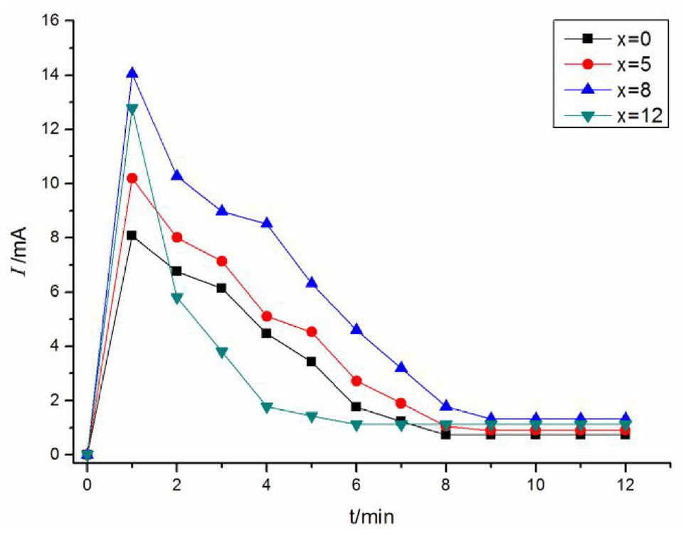
The current-time curve during anode bonding of (PEG)10LiClO4-x%CeO2 and aluminum foil.
Under the action of a strong electrostatic field, freely-moving ions inside the bonding material migrated at the beginning of the bonding process, which generated a strong current and reaction at the bonding interface to form a bonding layer. When CeO2 particles diffused into the PEG matrix, the crystallinity of the composite material was reduced, and more freely-moving lithium ions were released, which improved the ionic conductivity. Therefore, compared with the sample without CeO2, the peak current bonded to the aluminum foil was improved, but excess CeO2 agglomerated inside the matrix and hindered ion migration. Thus, the peak current did not continue to increase.
Figure 8 shows the current-time curves during the bonding process of (PEG)10LiClO4-8wt.%CeO2 and Al at bonding voltages of 600, 700, and 800 V. As the voltage increased, the electric field strength increased, the dissociation of Li+ increased, and the electrostatic attraction between the materials also increased. This made the bonding closer between the bonding materials, promoting ion migration during bonding, and increasing the peak bonding current. This was conducive to contact between the surfaces to form a bonding layer.24,25
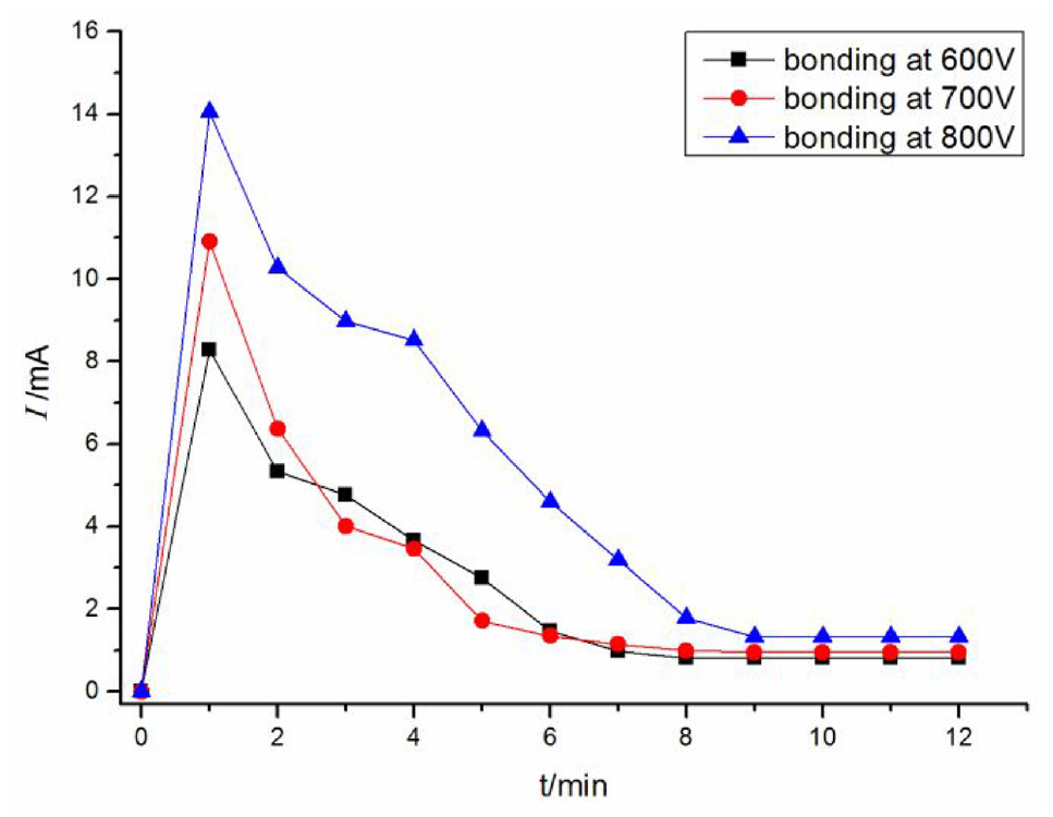
The current-time curve during anode bonding of (PEG)10LiClO4-8wt.%CeO2 and aluminum foil at different voltages.
Bonding interface analysis
Figure 9 shows the microscopic characterization of the interface between (PEG)10LiClO4-x%CeO2 and Al. At 5 and 8 wt.% CeO2, the interface was clear, and no pores or defects were observed. A bonding layer was formed between the polymer and the aluminum foil, and when the content was 8 wt.%, the bonding layer was slightly thicker. When CeO2 content was 12 wt.%, the bonding interface was uneven, and pores were observed on the side near the aluminum, which reduced the bonding quality.

The SEM image of bonding interface of (PEG)10LiClO4-x%CeO2 with Al: (a) x = 5, (b) x = 8, and (c) x = 12).
The tensile strength of the interface between (PEG)10LiClO4-CeO2 and aluminum foil at room temperature is shown in Table 4. When the content of CeO2 was 8 wt.%, the maximum tensile strength was reached (8.32 MPa). When the CeO2 content increased to 12 wt.%, the tensile strength of the bonding interface between the material and the aluminum foil decreased, but it was still higher than the sample without CeO2. This shows that the introduction of CeO2 can improve the tensile strength of the bonding interface and improve the bonding quality.
The tensile strength of bonding interface at room temperature.

Figure 10 shows the tensile fracture morphology of (PEG)10LiClO4-5%CeO2 and aluminum foil at room temperature. At 5 wt.% CeO2, a part of the broken aluminum foil side was not involved in the bonding. A white film-like substance remained in the part involved in the bonding, which was analyzed as a bonding layer, indicating that the bonding layer had fractured.

The tensile fracture morphology of (PEG)10LiClO4-5%CeO2 and Al: (a) Al and (b) DSPE.
Figure 11 shows that when the CeO2 content was 8 wt.%, a large, white substance remained on the surface of one side of the aluminum foil, and pits with different sizes formed on the polymer surface. This indicates that fracture occurred at the bonding base material, indicating a higher bonding layer strength and a better bonding quality.

The tensile fracture morphology of (PEG)10LiClO4-8%CeO2 and Al: (a) Al and (b) DSPE.
Conclusion
In this paper, a conductive polymeric material containing a rare earth oxide (CeO2) was prepared by mechanized alloying and hot-pressing. The AC impedance spectra, XRD, DSC, and anodic bonding results demonstrated that when the CeO2 content was 8 wt.%, the crystallinity of the composites was greatly decreased, and the amorphous region inside the material increased. This promoted ion transport, improved the conductivity, increased the peak current of the bonding process, and improved the bonding efficiency. The SEM images and mechanical strength test results showed that adding CeO2 improved the interfacial performance and mechanical properties. The tensile strength of the bonding interface of (PEG)10LiClO4-8%CeO2 and Al reached 8.32 MPa, and tensile fracture occurred in the base material. Thus, the material exhibited good bonding performance and formed an ideal bonding interface.
Footnotes
Handling Editor: James Baldwin
Declaration of conflicting interests
The author(s) declared no potential conflicts of interest with respect to the research, authorship, and/or publication of this article.
Funding
The author(s) disclosed receipt of the following financial support for the research, authorship, and/or publication of this article: This study was supported by the National Natural Science Foundation of China (No. 51875384).