
Abstract
In the dynamic balancing procedure of the rotor system, the unbalance is determined as a principal parameter which should be identified firstly. In actual engineering, the interference of external noise on the rotor is usually the main factor influencing the identification. In this paper, we focus on the unbalance identification of the power turbine rotor while the vibration response is influenced by signal interference during the balancing process in actual engineering. Fast Fourier Transform (FFT) and wavelet transform are used to analyze the collected original signal. Butterworth filter and Chebyshev type I filter are employed to test signal processing. The transient dynamic balancing method and the single plane influence coefficient method are used to balance the three balancing bosses of the rotor, and the balance efficiency is compared. The results show that, the signal fluctuation of boss 3 in high-frequency band is less than boss 1 and boss 2. Butterworth filter is more effective than Chebyshev type I filter in filtering the transient response data. The transient dynamic balancing method requires one test run without any trial-weights. More importantly, compared with the influence coefficient method, the transient dynamic balancing method has a better balancing effect.
Introduction
The rotor system is the core component of an aero-engine. When the rotor rotates at a high speed, the deviation between the centroid of the rotor and the center of rotation will cause the engine vibration.1–3 Most of the sharp vibrations are harmful to the engine, reducing the efficiency of the engine and some parts are easy to wear, fatigue, and shorten life. What’s more, the vibration exceeds the standard, causing shutdown, bringing huge economic losses, causing various serious accidents.4–6 Unbalance, misalignment, cracks, 7 and rubbing8,9 are the most common faults. 10 However, research and engineering practice show that unbalance is the main cause of vibration to a normal rotor. Once the balance of the rotor is improved, most of the faults will disappear. So the dynamic balance of flexible rotor has become an essential step in aeroengine design and manufacture.
Grobel 11 proposed a balancing technique similar to the modal balance method, which is a balancing scheme specially designed for turbine rotors, and may also be the earliest description of the modal balance theory. Federn 12 proposed the idea of modal balance clearly and later Hundal and Harker 13 and Kellenberge 14 enriched it. Thearle 15 proposed a two-plane, two-sensor, single-speed rotor field balance method, which has included the basic idea of influence coefficient method. Baker 16 summarized and extended Thearle’s method. Goodman 17 made a comprehensive and systematic discussion on the influence coefficient method in 1964 and elaborated the theoretical basis of the influence coefficient method.
With the increasingly extensive application of rotor system, various problems related to balance appear constantly. On the basis of the traditional steady-state equilibrium method, different improvement methods are proposed for some practical problems in the process of balancing. The balancing method without trial weight of the rotor is to simulate the actual rotor system according to the measured rotor vibration, and to predict the unbalance of the rotor from the mathematical point of view. Applying this method can reduce the steps of adding weights and the number of starts, which improve the balance efficiency. Gnielka 18 and Morton 19 studied the trial-free modal balance technology of a flexible rotor. Lu20,21 analyzed the stability of the balancing effect of multiple automatic ball balancing surfaces both theoretically and experimentally. Wang 22 realized the balance of the flexible rotor through sequence quadratic programming (SQP) based on holographic spectrum technology. Xu et al. 23 on the basis of the influence coefficient method, realized the trial-free balance of the flexible rotor through the optimization search of genetic algorithm, and verified the balance results through experiments. Zheng et al. 24 derived the equations of the rotor system by the Ricatti Matrix method, and succeeded in rotor balancing by measuring the unbalance response of bearing block. EI-Shafei et al. 25 proposed a trial-free balancing method using complex modes and measuring complex vibrations to balance the flexible rotor. Zhao et al. 26 proposed a transient characteristic-based balancing method (TCBM), the effectiveness of TCBM method is verified by experimental comparison. The transient high-speed dynamic balancing method without trial weight is a new high-speed dynamic balancing method which takes the measured rotor acceleration transient response information as input and combines the rotor natural mode information to identify the rotor unbalance.
The rotors of turboshaft engines and turbofan engines have a certain initial unbalance.27–29 Although many rotor systems are equipped with unbalanced passive suppression devices, axial vibration is still inevitable at adjacent critical speeds. In this paper, the method of transient dynamic balance without trial weight is applied to the power turbine rotor, to get better application in engineering practice.
Dynamic balance and filtering method
Dynamic balancing method
Transient dynamic balancing method without trial weight
The transient characteristic based balancing method (TCBM) is used in the transient dynamic balancing of the power turbine rotor without trial weight.
The basic principle of TCBM method is: the system response data
It can be expressed as the following form:

After analyzing the amplitude and phase, the unbalance excitation force vector calculated by DLI technique can be used to calculate the unbalance parameters of the rotor.
Dynamic balance method of single plane influence coefficient. 17
Under the assumption of linear system, the correction weight
For the single plane influence coefficient method, the influence coefficient is:

Where,
After the correction weight

When the residual vibration is 0, the corrected weight is:

Filtering technique
The test data of the power turbine rotor is easily affected by high-frequency noise, making the main characteristics of the response information not obvious. The unstable response data affected by noise may cause the two proposed dynamic balancing methods to fail when balancing the power turbine rotor. As a basic means to eliminate noise in the signal, the filter plays an important role in the actual rotor vibration signal processing.
Chebyshev type I filter
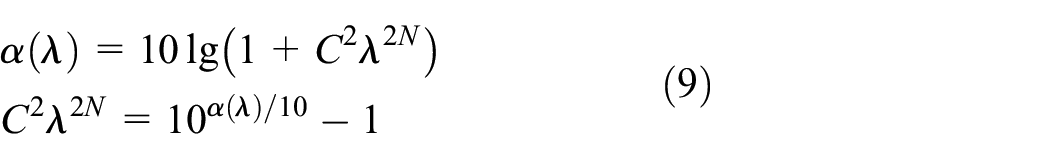
Amplitude-frequency characteristics of Chebyshev type I analog low-pass filter:

In the formula,

Using Chebyshev polynomials for filter design, the independent variables of (6) should be converted to normalized frequencies
Butterworth low pass filter
The amplitude-frequency characteristics of the Butterworth low-pass filter are:

Among them,

Meanwhile,
When
If
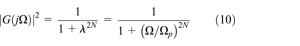
The Butterworth low-pass filter can be obtained from the above formula.
In this section, two balancing methods, transient dynamic balancing method without trial weight and classic single-plane influence coefficient balancing method, are compared. Two filtering methods are applied to deal with the noise that affects the transient response signal of the power turbine rotor in the test. Then we plan to realize the filtering of the rotor vibration response data in Chapter 3, and use the filtered data as input to realize the dynamic balance process of two methods in Chapter 4.
Signal analysis and processing of transient response
In order to verify the unbalance recognition accuracy and balance effect of the proposed transient dynamic balancing method on the actual rotor, transient response data was collected from the power turbine rotor system of the turboshaft engine.
The introduction to experimental model of power turbine rotor
The power turbine rotor consists of a slender and flexible shaft. The rotor has the characteristics of hollow, thin wall and high aspect ratio. The rotor shaft is supported by elastic bearings and squeeze film dampers. The structural feature is that the turbine disk is placed at one end of the rotor. The model diagram of the power turbine rotor is shown in Figure 1.

The model diagram of the power turbine rotor.
The total length of the power turbine rotor (including the output shaft assembly) is longer than 1m, and the maximum diameter of the disk is greater than 0.3 m. The length of the hollow drive shaft is closed to 0.9 m, the outer diameter is less than 0.03 m (length-diameter ratio is > 30), and the hollow thin-wall structure (most of the wall thickness is about 0.02 m). The two-stage power turbine disks are fixed together by bolts. No.1 bearing and No.2 bearing are installed in the output shaft assembly (axial position: about 0.035 and 0.12 m respectively from the shaft end of the output end of the drive shaft). No.5 bearing and No.6 bearing are installed on the drive shaft (axial position: the shaft end from the flange end of the drive shaft is about 0.11 and 0.035 m, respectively). The No.5 bearing position has a squirrel cage elastic support.
Experimental test equipment
According to the three working states of the rotor, the power distribution of the rotor shaft is carried out. The rotational speed is measured by a photoelectric sensor. Each boss is equipped with a vertical sensor and boss 2 is equipped with an additional horizontal sensor to collect rotor vibration response data. At the same time, two acceleration sensors are installed on the Support 2# to monitor the vibration of the rotor and prevent damage to the rotor in case of emergency. The Schenker system is used to collect the original deflection information of the three bosses.
Experimental process
Installation diagram of dynamic balance experiment of power turbine rotor is shown in Figure 2.

Installation diagram of dynamic balance experiment of power turbine rotor.
As shown in Figure 2, the dynamic balancing test of the power turbine rotor is carried out on a horizontal high-speed rotating test bench. The experimental system is composed of a speed control system, air pressure control system, a power input system and a real-time monitoring system. The 400 KW DC motor inputs power from the right end of the gearbox shaft through a two-stage accelerator. The power turbine rotor is driven to rotate by the output shaft assembly. The state of the output shaft assembly used for testing is exactly the same as the state of the actual engine. It is fixed on the front bracket by an adapter. The rotor test bench has both high-speed and low-speed ends, and is equipped with a safety cover to prevent the drive motor from overloading. The air pressure control system should be vacuum pumped before the test. During the start-up process, the rotation speed was controlled by professional operators, and the average acceleration was about 13 rad/s2.
During the measurement process, the speed and displacement response of each boss must be measured to complete the dynamic balancing process of the rotor. Various test data are stored and converted to facilitate subsequent test analysis.
Experimental test results
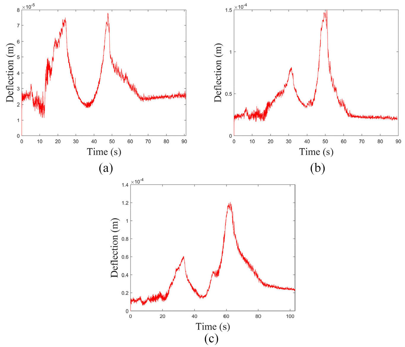
Six groups of starting processes are designed for dynamic balancing test of power turbine rotor: that is monitoring, collecting, storing, analyzing the displacement and speed data of the three bosses before and after the balancing. Due to the limitations of the Schenker acquisition system, only one boss’s displacement and rotation speed data can be collected at a starting process. Figure 3 shows the original deflection information of the three bosses before the balancing process collected by Schenker system. Figure 4 shows the change of rotation speed of the three bosses with time during the experiment.

The deflection graphs at each boss of the power turbine rotor: (a) boss 1, (b) boss 2, and (c) boss 3.

The speed at each boss of the power turbine rotor: (a) boss 1, (b) boss 2, and (c) boss 3.
It can be seen from Figures 3 and 4 that, due to the test environment and non-linear factors in the signal acquisition process, the original signal dynamic deflection cannot be well displayed. The curve is not smooth due to the interference in the process of speed rising. The collected signals are not suitable for the two balancing methods in Chapter 2. A preliminary filtering process should be applied to ensure the basic characteristics of the original signal, and then two dynamic balancing methods can be applied.
The introduction to experimental model of power turbine rotor
FFT was applied to frequency domain analysis of the original displacement of transient response data. The amplitudes in the frequency domain of the three balancing bosses are obtained, as shown in Figure 5. The analysis results show that the frequency of the rotor vibration signal after FFT transformation not only exist the main frequency and double frequency, but also exist interference signals.
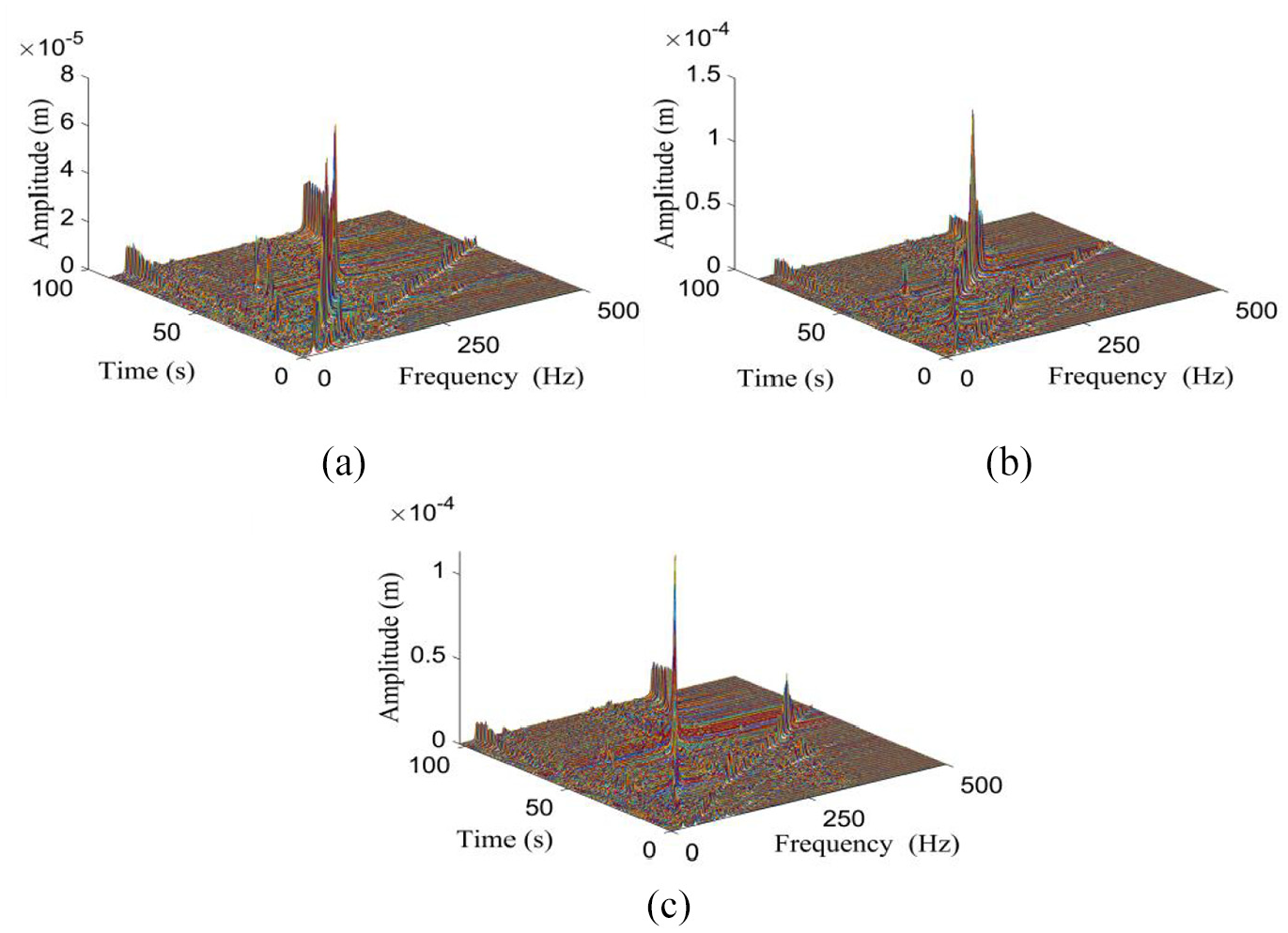
FFT transform amplitude diagram: (a) boss 1, (b) boss 2, and (c) boss 3.
Due to interference, the actual development trend of the signal cannot be observed from the original signal. The vibration signal is decomposed to 5-scale using wavelet transform, and the low-frequency and high-frequency coefficients after wavelet decomposition are obtained, as shown in Figures 6 and 7.

The low-frequency coefficient of wavelet decomposition: (a) boss 1, (b) boss 2, and (c) boss 3.
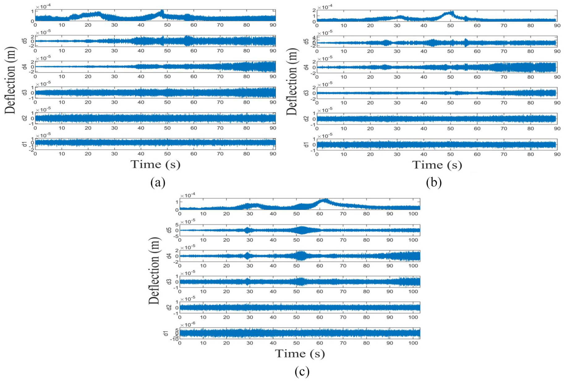
The high-frequency coefficient of wavelet decomposition: (a) boss 1, (b) boss 2, and (c) boss 3.
According to Figure 6, after decomposing and reconstructing the low-frequency coefficients, the approximate original transient dynamic deflection response diagrams of the three bosses can be obtained on the a5 layer. It can be seen that noise and interference have little impact on the displacement responses. Through the wavelet low-frequency coefficient decomposition, the signal development trend of boss 3 is better than boss 1 and boss 2. Combined with FFT frequency domain analysis, it can be seen that the signal fluctuation of boss 3 in high-frequency interference is less than boss 1 and boss 2. So the noise interference of boss 3 is the weakest in three bosses. It can be seen from Figure 7 that the original transient dynamic deflection response has lost its signal development trend after being decomposed by high-frequency coefficient. It is found that boss 2 is most affected by high-frequency noise comparing figure (a), (b), and (c).
After FFT analysis and wavelet decomposition analysis, it is found that the existence of interference greatly affects the accuracy of signal acquisition. In the process of rotor dynamic balancing, interference signals have great impact on the accuracy of unbalance identification. From the above analysis, it can be concluded that the spectrum of fundamental frequency signal, noise signal, and interference does not overlap, an appropriate filter can remove the noise. In this paper, different filtering methods are used to analyze the transient deflection. The redundant content in the signal including the mixed noise and interference has been filtered out, converted the signal to a special form that is easy to analyze and recognize. Then to extract the characteristic parameters and improve the balance accuracy.
Butterworth filter, Chebyshev type I filter are applied to process transient dynamic deflection data. The results after processing are shown in Figure 8 to Figure 9. Observe Figures 8 and 9, after filtering, the transient dynamic deflection curve has been reserved for the original characteristic of amplitude. Before and after filtering, the amplitude and position of the first critical velocity and the second critical velocity are significantly unchanged. It demonstrates that the proposed noise filtering method will not affect the accuracy of the original signal.

The deflection graphs of power turbine rotor after Butterworth low-pass filterer: (a) boss 1, (b) boss 2, and (c) boss 3.
The deflection graphs of power turbine rotor after Chebyshev I filter: (a) boss 1, (b) boss 2, and (c) boss 3.
During the transient start-up process of the rotor, the filter processing effect is poor at the initial and reaching the rated operating speed, which proves that the interference received when the rotor starts and stops is relatively large. The denoizing effect of the boss 3 is better than other bosses, which verifies the conclusion that the boss 3 is least affected by noise in the signal analysis and processing. Both filtering methods have obvious denoizing effects, which verify the effectiveness of the filtering methods. The results indicate that the effect of Butterworth filter is better than the Chebyshev I filter.
Analysis of dynamic balance results of power turbine rotor
Analysis of dynamic balance result of power turbine rotor at boss 2
The key phase signal and displacement of the boss 2 are collected through the software and hardware system, then the unbalance calculation of power turbine rotor is carried out. The balance weight is calculated to be 0.28 g ∠ 5°, and the balance weight is to add copper wire with different quality and orientation near the rotor boss in the form of turns.
The actual balance weight added near the rotor boss 2 is 0.34 g < 5°. Restarting rotor, the key phase signal and displacement of boss 2 are collected by the software and hardware system. The relationship between rotor deflection before and after balance with time is obtained, as shown in Figure 10.
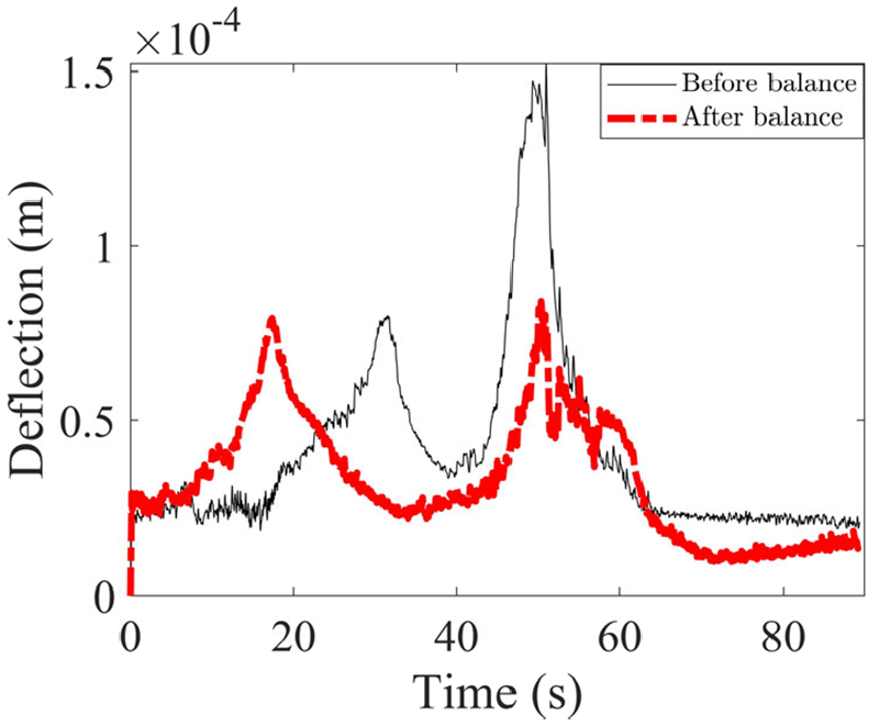
Balance effect diagram of power turbine rotor without trial weight at boss 2.
When the transient high-speed dynamic balance of the power turbine rotor without trial weight is carried out at boss 2, it can be obtained from Figure 10 that the first-order amplitude of the rotor decreases by 22.32%, the second-order amplitude by 44.46% and the amplitude at the working speed by 32.75%.
Taking 0.34 g < 5° as the trial weight, the influence coefficient of the rotor at working speed was balanced. Through the influence coefficient method, the balance weight to be added at boss 2 is 0.17 g < 304°.
The actual balance weight added near the boss 2 of rotor is 0.17 g < 304°. Restarting rotor, the key phase signal and displacement of boss 2 are collected by the software and hardware system, and the variation of rotor deflection with time before and after balance is shown in Figure 11.

Balance effect diagram of power turbine rotor influence coefficient method at boss 2.
It can be seen from Figure 11 that the first-order amplitude of the rotor is reduced by 15.31%, the second-order amplitude increases by 34.41%, and the amplitude at the working speed increases by 53.71%.
The balance results of the two methods are shown in Table 1. From the final balance data, the amplitude of the balancing without trial weight method has significantly reduced at the second-order critical speed and working speed, especially the amplitude at the second-order amplitude is reduced by 44.46%. However, the first-order amplitude of the influence coefficient method has little changed and the amplitude of second-order and working speed tend to increase. It can be concluded that the transient high-speed dynamic balancing method without trial weight has a better effect on the boss 2.
Summary of balance results at boss 2.

Analysis of dynamic balance result of power turbine rotor at boss 3
The key phase signal and displacement of the boss 3 are collected through the software and hardware system, then the unbalance calculation of power turbine rotor is carried out. The balance weight is calculated to be 0.27 g < 8°, and the balance weight is to add copper wire with different quality and orientation near the rotor boss in the form of turns.
The actual balance weight added near the rotor boss 3 is 0.29 g < 8°. Restarting rotor, the key phase signal and displacement of boss 3 are collected by the software and hardware system. The relationship between rotor deflection before and after balance with time is obtained, as shown in Figure 12.

Balance effect diagram of power turbine rotor without trial weight at boss 3.
It can be seen from Figure 12 that the effect of transient high-speed dynamic balancing of power turbine rotor without trial weight at boss 3 is not obvious. The first-order amplitude of the rotor is reduced by 33.73%, the second-order amplitude is reduced by 21.13%, and the amplitude at the working speed is reduced by 26.78%.
Taking 0.29 g < 8° as the trial weight, the influence coefficient balance of the rotor at working speed was carried out. Through the influence coefficient method, the balance weight to be added at boss 3 is 0.33 g< 315°.
The actual balance weight added near the boss 3 of rotor is 0.29 g < 315°. Restarting rotor, the key phase signal and displacement of boss 3 are collected by the software and hardware system, and the relationship between rotor deflection before and after balance with time is obtained, as shown in Figure 13.

Balance effect diagram of power turbine rotor influence coefficient method at boss 3.
It can be seen from Figure 13 that after the power turbine rotor influence coefficient method balance is performed at the boss 3. The first-order amplitude of the rotor is reduced by 41.06%, the second-order amplitude increases by 19.71%, and the amplitude at the working speed is reduces by 8.79%.
The balance results of the two methods are shown in Table 2. From the final balance data, the amplitude of the balancing without trial weight method has significantly reduced at the first-order, second-order critical speed, and working speed, especially the amplitude at the working speed is reduced by 26.78%. However, the first-order and working speed amplitude of the influence coefficient method has decreased greatly. It can be concluded that the transient high-speed dynamic balancing method without trial weight has a better balance effect on the boss 3.
Summary of balance results at boss 3.

Analyze and compare the dynamic balance effects of the transient dynamic balancing method without trial weight and the single plane influence coefficient method on the boss 2 and the boss 3. Under the second-order critical speed and working speed of the two bosses, the deflection reduction under the transient dynamic balancing method without trial weight is better than the influence coefficient method. The effect of boss 2 is better than that of boss 3 at the second critical speed and rated operating speed. To sum up, the power turbine rotor runs smoothly during transient start, and can achieve a good dynamic balance effect after transient dynamic balancing without trial weight.
By analyzing the experimental results, the balance effect of boss 1 is the worst, boss 2 and boss 3 had significant balance effects. It is analyzed that the rotor system structure boss 1 is too close to the turbine disk 1, and the response amplitude tends to be stable. To sum up, the dynamic balance results of boss 1 are not analyzed separately, but the dynamic balance results of boss 2 and boss 3 are mainly analyzed to prove the feasibility of the method.
Conclusion
In this paper, the effects of different digital signal analysis and processing methods on the unbalanced response with noise and interference are studied by numerical simulation. The reliability of signal processing in engineering practice is analyzed. In addition, a new balancing method is used to balance the power turbine rotor, and the results are compared with the influence coefficient method. Some conclusions can be summarized as follows:
Through the analysis of the original unbalanced response data by Fast Fourier Transform (FFT) and wavelet decomposition, it is found that there is interference in the signal acquisition process. Raw data features cannot be shown. The influence of noise interference on boss 3 is the weakest among the three bosses.
After digital signal processing, the amplitude and position of critical speed and rated speed have no obvious change. Compared with Chebyshev type I filtering method, Butterworth filter has better filtering effect on transient response data of power turbine rotor.
The transient dynamic balancing method without trial weight and the influence coefficient method are used to balance the power turbine rotor. Compared with the balance results, the transient dynamic balancing method without trial weight has a better balance effect.
The transient dynamic balancing method without trial weight is used to balance the power turbine rotor at boss 2 and boss 3. Comparing the balance effect of boss 2 and boss 3, it was found that the balance effect of boss 2 was better.
Footnotes
Handling Editor: James Baldwin
Declaration of conflicting interests
The author(s) declared no potential conflicts of interest with respect to the research, authorship, and/or publication of this article.
Funding
The author(s) disclosed receipt of the following financial support for the research, authorship, and/or publication of this article: This study was funded by the National Natural Science Foundation of China (Grant Number 11972295).