
Abstract
The knitting principle of 3D braided gear was studied, and the dynamic model of the two-stage gear system was established. The fourth-order Runge-Kutta method was used to numerically simulate the dynamic characteristics of common gear and 3D braided gear. The results showed that the fundamental frequency ω1 of the static transmission error excitation had the greatest effect on the speed and frequency characteristics of the first-stage gear along the meshing line. The research on frequency characteristics of common gear and 3D braided gear shows that the fundamental frequency ω1 of the static transmission error excitation has a large effect on the speed and frequency characteristics of the first-stage gear along the meshing line. With the reduction of the gear mass and moment of inertia, the amplitude in the low-frequency band increases. The vibration resonance of the system is studied by defining the amplitude gain of the response of the system output at the low-frequency signal ω3. The results show that with the reduction of gear mass and moment of inertia, when the input stage torque fluctuation frequency is Ω > 5, the fluctuation of amplitude gain Q disappears, which indicates that the vibration resistance of the 3D braided gear to high-frequency input stage torque fluctuation frequency is greatly improved.
Introduction
Textile composite material is a kind of composite material formed by weaving fiber bundles into the required structural shapes of parts by using textile technology, and then impregnating and curing them by using resin film infiltration and other processes. In recent years, with the needs of aerospace and other fields for the properties of impact resistance, interlaminar shear and light weight, 3D woven composite materials have been widely used and studied.1–4
In rectangular braiding and mechanical properties, Xu et al. analyzed the advantages, uses, disadvantages and deficiencies of 3D braided composites. By selecting a representative volume element (RVC) to study the influence of different braiding angles on the mechanical properties of braided composites. 5 Chen et al. studied the microstructure of 3D braided preform produced by four-step method, analyzed the structural geometry of preform, and derived the mathematical relationship among structural parameters such as yarn stacking factor, fiber orientation, fiber volume fraction, braiding spacing, etc. It was verified that the calculated values of geometric characteristics of braided composite samples were in good agreement with the measured values. 6 Zhang et al. established three different solid structure models of inner, surface and corner elements of 3D rectangular braided composites, simulated the mechanical properties of 3D rectangular braided composites with finite element method, and gave the deformation and stress distribution of the three element models, and studied in detail the influence of braiding angle and fiber volume fraction on elastic constants of 3D braided composites, which laid a foundation for the application of braided composites in aerospace field.7–9
In the aspect of ring knitting and mechanical properties, because the macroscopic structure of yarn is different in different radial positions, the microscopic geometry of 3D braided ring preform is more complex than that of rectangular preform.10,11 Wang et al. carried out finite element analysis on 3D circular braided composite pipe, and established a circular element model by geometric drawing method. The deformation and stress distribution are obtained by finite element analysis of the annular element, and the influence of weaving parameters on the longitudinal modulus is studied by comparing the predicted longitudinal modulus with the experimental results. 12 Ma et al. divided the circular braiding into different regions according to the different movement modes of yarns in the circular braiding, and established the unit geometric model corresponding to different regions. By using this model, the mechanical characteristics of braiding can be accurately described, which laid a theoretical foundation for the structural design of three-dimensional and five-directional circular braiding. 13 Hwan et al. predicted the elastic modulus of three-dimensional braided tube by using space spring model, and studied the influence of braiding parameters on the effective elastic modulus of 3D braided tube. At the same time, relevant compression tests were carried out to verify the calculation results. 14
At present, 3D multi-directional braided composite materials have been used in the fields of satellite load-bearing space truss structure, high-temperature and ablation-resistant missile nose cone, rocket engine nozzle and so on.7,8
The paper has been divided into five sections. In Sec. 2, the forming principle of 3D braided gear is analyzed. In Sec. 3, based on the consideration of backlash, time-varying meshing stiffness and meshing error, the differential equation of motion of the two-stage tooth transmission system is established by using the Lagrange equation. The characteristics of the system are studied by the speed time history diagram, phase plan, Poincaré map and FFT spectrum of the main and driven gears along the meshing line. In Sec. 4, the system vibration resonance is studied by defining the response amplitude gain of the system output at the low-frequency signal. In Sec. 5, we state the main conclusions. Through the research in this paper, it is found that with the decrease of mass and inertia of 3D braided gears, the amplitude and frequency of gears change during rotation, which indicates to some extent that the vibration resistance of 3D braided gears is better than that of ordinary gears.
Forming principle of 3D braided gear
The common compiling method used for 3D braided gear is four-step circular knitting, the circular knitting method is similar to the rectangular knitting method. the difference lies in that the coordinate system of circular knitting is the polar coordinate system, the working principle of four-step circular knitting is illustrated in Figure 1 with the example of 3 × 18 (M = 3, N = 18, M is the number of circumferentially woven fiber layers, and N is the number of radially woven fiber columns). In the first step, the row yarn carriers move one position in a staggered way in the radial direction. In the second step, the row yarn carriers move alternately by one position in the circumferential direction. In the third step, the row yarn carriers move one position in a staggered way in the radial direction. The fourth step, the row yarn carriers move alternately by one position in the circumferential direction. According to the above movement, the yarn carrier forms a machine cycle after four steps, and the length of the prefabricated part obtained after one cycle is called a knitting knuckle length h, and the woven prefabricated part with the required length can be obtained by circulating in turn.10,14

Working principle of four-step circular knitting.
In the four-step circular knitting, there is no additional yarn in the circumferential direction for the number of yarns, so the calculation formula of the total number of yarns S is as follows 5 :

In the equation (1), M is the number of circumferentially woven fiber layers, and N is the number of radially woven fiber columns and must be an even number, otherwise, there must be two adjacent columns of yarn carriers with the same motion trajectory. In Figure 1, the total number of yarns is S = (3+1) × 18 = 72.
In the four-step circular weaving, the weaving grain angle α formed on the surface of the preform is defined as the weaving angle. The weaving angle α is an important weaving process parameter, and the tangent of the weaving angle is equal to the ratio of the flower node width to the flower node height on the surface of the preform (as shown in Figure 2) 3 :
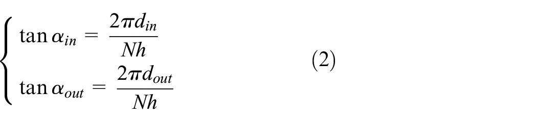

Model of gear braided fiber bundle.
In the equation (2),
The yarn carrier continuously circulates the four-step motion and gradually weaves into a required braided yarn preform; the braided yarn preform is dipped, pressed and cured in a liquid matrix to form an annular braided composite material; Figure 2 is a diagram of a braided fiber bundle model obtained by a four-step motion; Figure 3 is a gear matrix model; and Figure 4 is a braided gear model composed of a matrix and fibers.

Gear matrix model.

The 3D braided gear.
The 3D braided gear is composed of high-strength and high-modulus carbon fiber and matrix. Carbon fiber provides structural rigidity and strength of composite material, while matrix fixes carbon fiber and disperses and transmits load between carbon fibers.7,8 Compared with traditional metal gear, 3D braided gear has many advantages such as good comprehensive mechanical properties, light weight and good shock absorption. In this paper, T300 carbon fiber is used for knitting yarn, and its density is 1.8 g/cm3, the matrix is TDE-86 epoxy resin with a density of 0.980 g/cm3. The mass calculation formula of 3D braided gear is as follows:

In equation (3),
The moment of inertia of the 3D braided gear can be calculated by equation (4):

In equation (4),
Dynamic analysis of two-stage braid gear system
The dynamic model of the two-stage gear system is shown in Figure 5. Considering the backlash, time-varying meshing stiffness and meshing error, the dimensionless differential equation of motion of the two-stage gear transmission system is obtained according to Lagrange equation as shown in equation (5)15–17:


Dynamic model of two-stage gear system. 16
In equation (5),

In equation (6),
In equation (5),
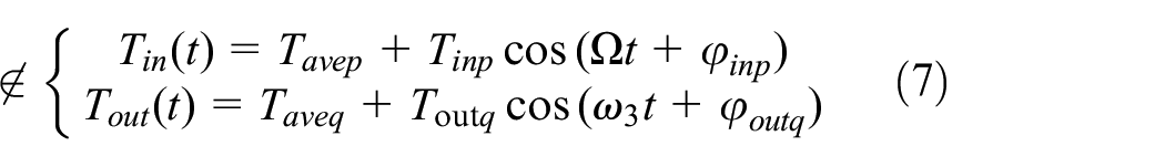
In equation (7),
Because the physical quantities In the equation (5) differ greatly in order of magnitude, differential equations such as equation (5) are generally treated as dimensionless in mathematics. Define the time scale
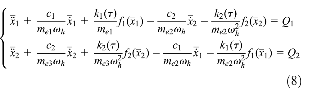
In equation (8),
In equation (8),


In the equations (9) and (10),
In equation (8),

With the simulation parameters shown in Tables 1 and 2, the numerical solution of differential equation (8) is obtained by using the fourth-order Runge-Kutta method shown in equation (11), and the speed-time history diagram (Figures 6(a) and 7(a)), phase plan diagram (Figures 6(b) and 7(b)), Poincaré map (Figures 6(c) and 7(c)), and FFT spectrum diagram (Figures 6(d) and 7(d)) of the first-stage and second-stage gears along the meshing line direction are obtained.
Common gear parameters.

Simulation parameters.


Simulation results of the speed of the first-stage gear along the meshing line: (a) time series, (b) phase diagram, (c) poincaré diagram, and (d) spectrum diagram.

Simulation results of the speed of the second-stage gear along the meshing line: (a) time series, (b) phase diagram, (c) poincaré diagram, and (d) spectrum diagram.
In Figures 6 and 7, the initial conditions are
As can be seen from Figures 6(a) and 7(a), the velocity time series curve of the first and second gears along the meshing line is composed of signals of many different frequencies superimposed together. As can be seen from Figures 6(c) and 7(c), Poincaré diagram presents irregular discrete points.
It can be seen from Figures 6(b) and 7(b) that the phase diagram is roughly a quasi-periodic motion zone. It can be seen from Figures 6(d) and 7(d), the first-stage excitation fundamental frequency ω1, input signal fluctuation frequency Ω and first-stage time-varying stiffness fundamental frequency ω11 have great influence on the speed and frequency characteristics of the first-stage gear along the meshing line, among which the first-stage static transmission error excitation fundamental frequency ω1 has the greatest influence, while the second-stage excitation fundamental frequency ω2, output signal fluctuation frequency ω3 and second-stage time-varying stiffness fundamental frequency ω22 have great influence on the speed and frequency characteristics of the second-stage gear along the meshing line, among which the second-stage static transmission error excitation fundamental frequency ω2 has the greatest influence.
Since the mass of 3D braided gear is much lower than that of traditional metal gear, it is necessary to analyze the dynamic characteristics of gears with different masses. Figure 8 for quality affects the amplitude frequency characteristics, Figure 8 is the first-stage in the direction along the meshing gear speed frequency characteristic figure, Figure 8(a) shows that the static transmission error excitation fundamental frequency ω2, the output signal fluctuation frequency ω3 and the secondary fundamental frequency time-varying stiffness ω22, on the first-stage gear along the line of action have little impact on the direction of the velocity amplitude frequency characteristic curve. The first-stage excitation fundamental frequency ω1, input signal fluctuation frequency Ω, first-stage time-varying stiffness fundamental frequency ω11, on the first-stage gear along the line of action have a great influence on the direction of the velocity amplitude frequency characteristic curve, with the decrease of gear mass, the amplitude increases.
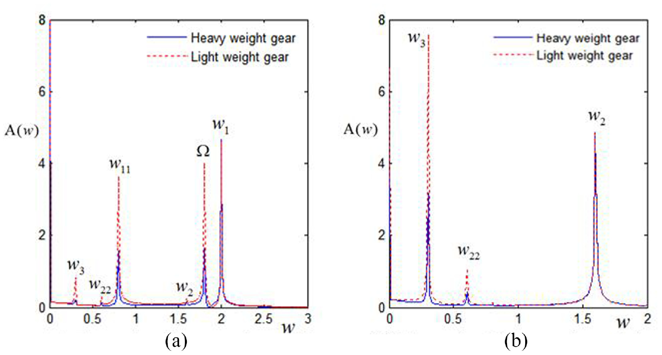
Influence of mass on frequency characteristic amplitude.
Figure 8(b) shows the static transmission error excitation fundamental frequency ω2, the output signal fluctuation frequency ω3 and the secondary fundamental frequency time-varying stiffness ω22 have a great influence on the amplitude of the velocity and frequency characteristics curve of the second-stage gear along the meshing line. The first-stage excitation fundamental frequency ω1, the input signal frequency fluctuations Ω and first-stage time-varying stiffness fundamental frequency ω11 have little impact on the amplitude of the velocity and frequency characteristics curve of the second-stage gear along the meshing line. With the decrease of the quality of gear, low frequency amplitude increases, the high frequency amplitude increase is not obvious, this suggests that the 3D braided gear quality is light, not less than ordinary metal gear vibration resistance.
Vibration resonance analysis of two-stage braided gear system
Nonlinear systems under different frequency signal excitation vibration resonance phenomenon is first put forward by Landa and McClintock,18,19 they, in the study of stochastic resonance noise with high frequency excitation signal, and find that the amplitude of the system response to low frequency signal and high frequency signal amplitude changes to present a nonlinear relation, namely resonance vibration. The complex equation (8) frequency components input stage in high speed, torque ripple frequency Ω can be regarded as the high frequency signal.20–22 The output stage torque wave frequency ω3 is in the low speed stage, torque ripple frequency ω3 can be regarded as the low frequency signal. The equation (12) is used to define the response amplitude gain
In equation (12),
No interference is considered
Based on the model of equation (8), when the torque amplitude of the driving gear

Influence of
In Figure 9(c), J1 = 0.0365e-3 kg.m2, J2 = 4.38e-3 kg.m2, J3 = 0.1095e-3 kg.m2, J4 = 2.92e-3 kg.m2, Figure 9(d) is a projection diagram corresponding to Figure 9(c). Comparing (a)–(d) in Figure 9, it can be seen that with the decrease of gear moment of inertia, the amplitude gain Q increases, but the number of weak vibrations decreases.
The mass and moment of inertia of each gear in Figure 9(e) are shown in Table 3, and Figure 9(e) is a projection diagram corresponding to Figure 9(f). By comparing (c)–(f) in Figure 9, it can be seen that with the reduction of gear mass and moment of inertia, the fluctuation of amplitude gain Q >5 disappears, indicating that the vibration resistance has been greatly improved.
3D braided gear parameters.

Consider noise interference
On the basis of equation (8) model, noise interference with amplitude of 0.000001 is added. The mass and moment of inertia of each gear in Figure 10(a) are shown in Table 1, Figure 10(b) is a projection drawing corresponding to Figure 10(a). The mass and moment of inertia of each gear in Figure 10(c) are shown in Table 2, Figure 10(d) is a projection drawing corresponding to Figure 10(c).

Influence of
Comparing the four figures, it can be seen that when the torque amplitude of the driving gear
On the basis of equation (8) model, noise interference with amplitude of 0.000001 is added. The mass and moment of inertia of each gear in Figure 11(a) are shown in Table 1, and Figure 11(b) is the projection diagram corresponding to Figure 11(a). Comparing the four figures, it can be seen that when the torque amplitude of the driving gear and the fluctuation frequency of the input stage torque change in equation (6), the amplitude gain Q of the ordinary gear changes. The amplitude gain Q of 3D braided gear varies greatly, with the magnitude of 0.00006. However, comparing Figure 11(b) and (d), it is found that the extreme value of amplitude gain Q of ordinary gear (red area in b and d) is still far larger than that of 3D braided gear. Therefore, when the torque amplitude of driving gear and the fluctuation frequency of input stage torque change, the vibration resistance of 3D braided gear is better than that of ordinary gear.
Influence of
Conclusion
On the basis of studying the knitting forming principle of 3D braided gear, this paper establishes the motion differential equation of two-stage gear transmission system by using Lagrange equation, taking into account the factors such as the backlash, time-varying meshing stiffness and meshing error, and uses the fourth-order Runge-Kutta method to numerically analyze the system differential equation. It is found that the first-stage excitation fundamental frequency ω1, the input signal fluctuation frequency Ω and the first-stage time-varying stiffness fundamental frequency ω11 have great influence on the speed and frequency characteristics of the first-stage gear along the meshing line. Therefore, the speed and frequency characteristics of the first-stage gear along the meshing line can be changed through three signal frequencies: ω1, Ω, and ω11. The second-stage excitation fundamental frequency ω2, the output signal fluctuation frequency ω3 and the second-stage time-varying stiffness fundamental frequency ω22 have great influence on the speed and frequency characteristics of the second-stage gear along the meshing line. Therefore, the speed and frequency characteristics of the second-stage gear along the meshing line can be changed through three signal frequencies: ω2, ω3, and ω22. The vibration resonance analysis of the system without considering noise factors shows that with the decrease of gear mass and moment of inertia, the vibration resistance of the gear is improved. The vibration resonance analysis of the system considering the noise factor with the amplitude of 0.000001 shows that the amplitude gain Q of the 3D braided gear changes greatly with the change of the torque amplitude of the driving gear
Footnotes
Handling Editor: James Baldwin
Declaration of conflicting interests
The author(s) declared no potential conflicts of interest with respect to the research, authorship, and/or publication of this article.
Funding
The author(s) disclosed receipt of the following financial support for the research, authorship, and/or publication of this article: The project supported by Shaanxi Province Young Outstanding Talents Support Program Project (Program No. 106-451420001), and supported by Natural Science Basic Research Plan in Shaanxi province of China (Program No. 2019JQ-896).