
Abstract
Aiming at the problem that the geometric accuracy design index of machine tools is difficult to be determined reasonably in the geometric precision design process of CNC machine tools, this paper presents a mapping model between geometric tolerance of the workpiece and end pose error (positional and orientational error of the tool relative to the workpiece) of the machine tool considering structure distortion of cutting process system. Only considering the factors of the machine tool geometric errors, this paper first establishes the relationship between the geometric tolerance requirements of the workpiece and relative pose error at the end of machine tools, and completes the estimation of the machine tools end pose error. Then this paper analyzes the elastic deformations of the cutting process system caused by the cutting force. These elastic deformations produce machining errors. Based on the above analysis, the estimated variation range of the end pose error can be adjusted by the emulation of the geometric tolerance of the workpiece and used as the geometric accuracy design index of machine tools. This paper takes the international standard small size contour processing test piece as an example to explain the application process of the proposed model.
Introduction
Geometric accuracy is an important performance factor for CNC machine tools, especially for machine tools with higher accuracy requirement. 1
In the machining process, there are often many factors that affect the final processing quality of the workpiece. Among of these factors, the force deformation of the cutting process system and the geometric error of the machine tool occupy a prominent position. The cutting process system here refers to a whole system formed by machine tools, fixtures, tools, and workpieces during processing. Any part of the cutting processing system will produce certain structural deformation under the influence of cutting force to affect the processing accuracy of the workpiece. These deformations belong to structure distortion of cutting process system. The geometric error of the machine tools is the relative end pose error of the machine tool due to the geometry, surface quality, and posture error of the working surface of each component of the machine tools. It reflects the geometric accuracy of the machine tools. Therefore, considering the influence of the structure deformation of the cutting process system, ensuring the geometric accuracy of the machine tools is the most basic method to ensure the machining accuracy.2,3 During the design process, the geometric accuracy of CNC machine tools can be improved by reasonably distributing the manufacturing tolerances of key components according to the accuracy design index of the machine tool. Tolerance allocation at the design stage is also called precision design. It refers to the process of determining the size tolerance of each component ring economically and rationally on the premise of ensuring the technical requirements for product assembly. It directly affects the precision and manufacturing cost of the machine tools, and has been paid more and more attention by machine tool designers. 4
The current tolerance allocation methods all transform the accuracy design into a type of optimization problem that takes the key component tolerance as the design variable, the lowest manufacturing cost as the objective function, and the accuracy index as the constraint condition. Recently, there have been many solutions to optimize the tolerance allocation, including statistical tolerance synthesis, 5 adaptive genetic algorithm,6,7 fuzzy comprehensive evaluation method. 8 Every kind of these schemes shows its advantages and disadvantages, and they play an important role in different application areas. However, there is currently no appropriate solution to reasonably determine the accuracy design index of the machine tools, and it can only rely on the experience of the designer or comparing the accuracy index of the same type of machine tools. In order to solve this problem, this paper presents a mapping model of the workpiece geometric tolerance and CNC machine tool end pose error considering structure distortion of cutting process system. The significance of this model is to provide a method for designing the accuracy index of the machine tool according to the actual needs of the mechanical designer, and to provide a theoretical basis for the subsequent accuracy allocation work. For machine tool manufacturers, they can use this mapping model to accurately determine the variation range of the machine tool end pose error during the design stage, which would be helpful to enable the characteristic of machine tool to meet the requirements of customers.
Section 2 establishes the constraint relationship between the single tolerance item of the specimen and the machine end pose error, considering only the influence of the end pose error on the machining error, and completes the estimation of the end pose error of the machine tools. Based on the cutting force model of the machine tool, Section 3 derives the position error at the end of the machine tools due to the elastic deformation of the cutting process system. Combining the influence of the geometric accuracy and the structure distortion of cutting process system, Section 4 adjusts the estimated variation range of the end pose error by simulating the geometric tolerances of the workpiece based on Monte Carlo Method. The error range of the machine tool after adjustment can be used as the geometric accuracy design index of machine tools. Finally, Section 5 is the conclusion of this paper.
The estimation of machine tool end pose error range based on geometric tolerance requirements of the workpiece
The geometric error of the machine tool is reflected in the six degrees of freedom error at the end of the machine tool, including three position errors and three angle errors, which is described as the end pose error of the machine tool. Generally, these errors are caused through the mechanical imperfections of the machine tool structure and the misalignment of machine tool elements. 9 This part of the error is an important cause of machining errors. When ignoring the elastic deformation resulted by cutting force in the cutting process system, the relationship between the end pose error of the machine tool and the geometric tolerance of the workpiece can be established. This relationship can be used to estimate the variation range of the machine tools end pose error. That means, under the premise of considering only the influence of end pose error on the machining error, all parts processed can meet the tolerance requirements if the machine tools end pose error meets this variation range.
Basic theory
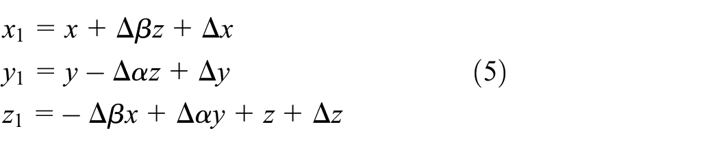
The six-dimensional pose error at the end of the machine tools can be expressed as:

where
Assuming that the target part has k items of geometric tolerance index. For any tolerance index of the target part
Each geometric tolerance index has a corresponding geometric tolerance zone. The geometric tolerance zone refers to the area used to limit the variation of extracted features. As long as the part extraction elements are in this area, the corresponding geometric tolerance item is qualified.
The basic assumption: the variation ranges of translational errors and rotational errors at the end of the machine tool should be consistent, such as:

Define the parameter
According to common form tolerances, orientation tolerances, location tolerances and run-out tolerances, the shapes of the tolerance zone can be divided into the following types: the area between two parallel planes, the area between cylindrical surfaces, the area between two concentric circles, and the area between two coaxial cylindrical surfaces. Several representative shapes of the tolerance zones and corresponding geometric tolerances are presented in Table 1.
Examples of several representative tolerance zone shapes.

Next, the small size contour processing test piece in the draft international standard ISO/DIS 10791-7 will be used as an example to illustrate the specific derivation process. 10 Then, a set of corresponding range of machine tools end pose error can be obtained.
Example
According to the process requirements, there are 13 geometric tolerance requirements for the test piece, as shown in Figure 1, and the inspection and tolerance requirements of the contour finishing test piece are shown in Table 2. The tolerance items (l) and (n) mainly are used to detect the two-axis linear interpolation precision when the feed rate of a certain axis is very low. Therefore, these two geometric tolerances can be ignored when only considering the geometric accuracy of the machine tools.

International standard small size contour processing test piece.
The geometric precision inspection requirements for contour finishing test pieces.

The following part take the roundness of the outer circle as an example to illustrate the variation range of the end pose error.
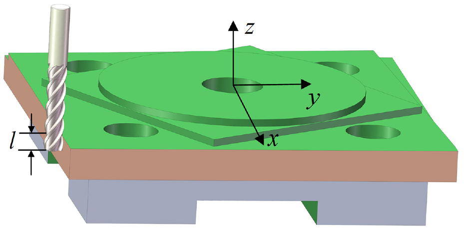
The processing schematic diagram of the outer circle is shown in Figure 2, where
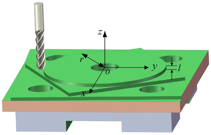
Processing schematic diagram of outer circle.
As shown in Figure 3, the roundness tolerance zone of the outer circle roundness is the area between two concentric circles whose radius difference is the tolerance value

Roundness tolerance zone area.
Transform the six-dimensional pose error

As shown in Figure 2, the theoretical cutting points of the measured circumference in the workpiece coordinate system can be assumed as

The coordinates of the actual cutting point are:
According to the definition of the roundness tolerance zone, in order to make the roundness tolerance meet the requirements, the coordinate requirements of the actual cutting point are:

When the design variables act alone or simultaneously, the independent constraint and comprehensive constraint of the design variables can be obtained separately.
The independent constraint is:
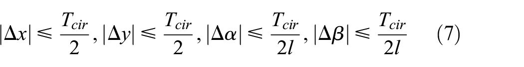
The comprehensive constraint is:

The comprehensive constraint can be reduced to:

Substituting the value
Similarly, the range of the design variables corresponding to the rest tolerance items of the contour processing test piece can be obtained, as shown in Table 3. It can be considered that
The range of the design variables.

It can be seen from Table 2 that the range of position error and angle error corresponding to each geometric tolerance item of the test piece is different. Among them, the tolerance items (a) and (b) have the strictest requirements on the allowable variation range.
Modeling of cutting force and machining error
In the cutting process, the CNC machine tool will also cause a certain degree of plastic deformation while applying cutting force. Larger cutting force will cause the deformation of the cutting process system. In the early research, the cutting force error is generally not considered, based on the fact that the cutting force is very small and the offset caused by it can be ignored in the final process. 12 In recent years, the problem of cutting force error has become more and more prominent. The main reasons include the application of difficult-to-machine materials, the increase in cutting depth and feed parameters, and the increase in machining accuracy, etc. The originally negligible cutting force error becomes more and more important.
In the field of machine tool processing, cutting force is a major factor that produces machine tool processing errors. Cutting force will directly cause deformation of the machine tool process system. At the same time, the increase in cutting force will increase the supporting reaction of the bearing and aggravate the wear of the bearing, which will cause thermal deformation of the parts of the machine tool. The increase in cutting force will also aggravate the wear of the tool, and then the tool will lose the correct tooth profile faster. These factors caused by cutting force can affect the accuracy of processing. 13
During the machining process, the cutting process system composed of machine tools, fixtures, tools and workpieces will produce certain elastic deformation caused by the action of cutting force. Any deformation of the components will affect the quality of the workpiece. 9 For the cutting process system, in the mechanical processing, the elastic deformation of the workpiece can be ignored if the stiffness is high. The deformation of the fixture is related to the clamping process, so it is not analyzed here. Therefore, this section mainly analyzes the elastic deformation of the tool and the machine tool caused by the cutting force. This part of the elastic deformation will cause relative position errors of the tool and the workpiece, which could be attributed to the machining error.
Cutting force model of machine tools
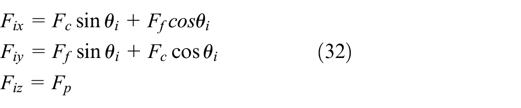
The cutting force of the machine tool changes during the actual processing. The effect of the total cutting force on machining error is complex. In the workpiece coordinate system, the total cutting force can be decomposed into component forces in three directions, including axial force

Schematic diagram of milling forces.
The influence of the main cutting force
There are five factors that affect the milling force, including milling depth
The empirical model of the total milling force is: 14

The empirical formula of component milling force is: 14

where
Tool deformation model
The rigidity of slender tool is relatively weak. The slender tool will deform and deviate from the ideal cutting position under the action of the milling force.
15
The tool is generally simplified as a cantilever structure, as shown in Figure 4. The cutting force acting on the tool in the Z direction causes the tool to stretch or compress. The cutting force acting on the tool in the X and Z direction cause the tool to bend. The tool deformation in the three axial directions at the point P can be expressed as
The elastic deformation of the tool in the X and Y directions includes the deformation of the handle and the deformation of the blade. Take the deformation of the tool by the cutting force in the X direction as an example, Figure 5(a) is a simplified schematic diagram of the tool. The deformation of the tool at point P is: 15

where

Tool deformation: (a) schematic diagram of the tool and (b) simplified deformation diagram.
Because of the different radius of the handle and the blade, the inertia moment of the two parts are different. The deformation of the tool is shown in Figure 5(b). The resultant cutter bending deformation is: 15

where
The deformation of the tool in the Z direction can be regarded as the axial deformation of the cantilever. According to Hooke’s law, the deformation in the Z direction is:

where
Due to the six-dimensional error at the end of the machine tool, the tool after clamping will have three corner errors. The machining error caused by the tool deformation can be expressed as

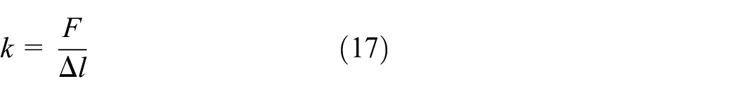
Mapping model of machine tool static stiffness and machining error
The force-deformation of the machine tool is usually elastic deformation. The ability of the machine tool to resist deformation is described as stiffness of the machine tool, which also directly affects the machining accuracy of the workpiece. 16
In the early stage of machine tool design, the static stiffness of the whole machine in X, Y and Z directions can be obtained based on the same type of machine tool or empirical design.
At the cutting point of the tool, the static stiffness of the whole machine in the X, Y, and Z directions are expressed as
The total milling force at the tool end is decomposed into three component forces along the coordinate direction, which are expressed as
where
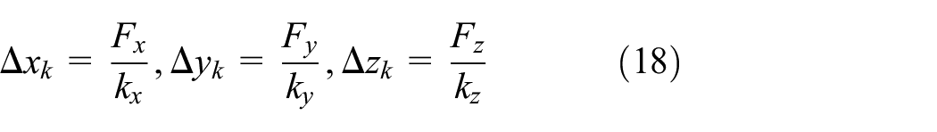
where
The machining error caused by the deformation of the machine tool transmission system can be expressed as:

Machining error caused by cutting force
During the milling process, the value of the cutting force changes in real time with different conditions of the processing material, cutting amount, feed amount, cutting speed, etc. There are many factors that affect the cutting force. The tool will produce impact or vibration during the actual processing. Assume that the amount of shock and vibration is small. In order to facilitate the calculation, the milling process of the tool can be regarded as the static stress distribution at a certain moment during the analysis. In the actual machining process, the friction between the tool and the workpiece will generate cutting heat to affect the machining error. This paper ignores the effects of cutting heat, tool wear and vibration.
This section considers only the elastic deformation of the cutting process system caused by the cutting force, and ultimately deflects the deformation to the machining error of the actual machining point. The machining error can be expressed as:

Adjusting machine tools end pose error range by Monte Carlo Method
The machining errors caused by the geometric error of the machine tool and the cutting process system exist at the same time. A geometric tolerance mapping model is established by Monte Carlo Method to obtain accurate machine tool end error.
Basic theory
Monte Carlo Method is also called random sampling or statistical experiment method. It uses mathematical methods to simulate problems by grasping the geometric quantity and geometric characteristics of moving things. So it is a digital simulation experiment. 17 The key of Monte Carlo Method is to create random sequence. Monte Carlo method can be used to connect actual problems with some properties of sequence to ensure the objectivity of the problem.
Since the machine tool end pose error is usually a variable range, the end error parameter are also random amounts. The geometric tolerances of the workpiece are variable ranges. Therefore, the Monte Carlo Method can be used to establish the mapping relationship between the geometric tolerance of the workpiece and the machine tool end pose error, which is equivalent to establishing a numerical relationship between the limit value of the machine tool end error and the limit value of the geometric tolerance. This section establishes the geometric tolerance model of the workpiece with the estimated machine tool end error variation range by the Monte Carlo Method.
The core idea of the geometric tolerance model is to add errors for the theoretical trajectory. The estimated range of the machine tool end pose error can be obtained from the second section. The estimated range is expressed as:

In this paper, the distribution functions of the pose error parameters are uniformly distributed.
Discrete the theoretical trajectory of the tool. In the workpiece coordinate system, the coordinate of the point

The error transformation matrix at this point is:
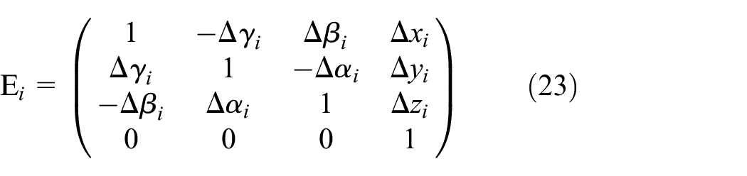
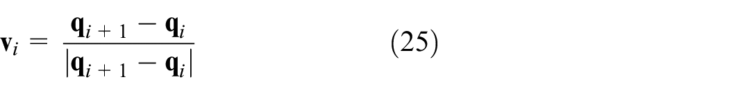
As shown in the Figure 6, the actual tool coordinates and tool axis are:

where

The schematic diagram of the tool trajectory.
See Figure 6 for the schematic diagram of the tool trajectory. Due to the influence of the machine tool end pose error, the movement direction of the actual cutting point is:
The actual cutting point position is:

where
The cutting process system will produce certain elastic deformation under the influence of cutting force. This part of the elastic deformation will affect the relative displacement of the tool and the workpiece. Therefore, the position coordinates of the actual cutting point are corrected to:

The actual contour trajectory can be obtained by calculating enough contact points. The geometric tolerance of the test piece can be assessed based on least square method and least regional method. The geometric tolerance value of the test piece obtained by simulation can be expressed as:

where
The geometric tolerance requirements of the test piece can be expressed as:

where
The specific adjustment process of the end error range is shown in Figure 7.

Flow chart of adjusting the end error range.
Calculation example
Based on the above analysis, the geometric tolerance simulation result can be obtained. Taking the small size contour processing test piece as an example, the following part presents the calculation of the outer circle roundness tolerance item and the outer square side straightness tolerance item to illustrate the adjustment process of the machine tool end pose error range.
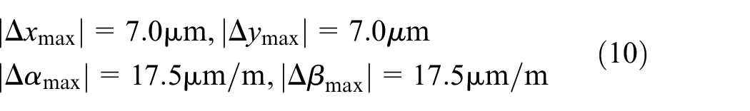
Modeling of the outer circle roundness tolerance item
According to the requirements of the outer circle roundness tolerance, the end pose error range estimated by Section 2 is expressed in equation (10).
The machine tool used for processing the test piece is a M630H precision horizontal machining center. In the early stage of machine tool design, the static stiffness of the machine tool in three directions are expressed as:

A carbide milling cutter is used for milling the outer circle. The parameters of tool are shown in Table 4.
The tool parameters.

The material of the test piece is cast aluminum alloy, and its international brand is expressed as AlSi9Cu3. The chemical composition of the test piece includes a great deal of aluminum, silicon and copper, a small quantities of magnesium, manganese, iron, zinc, titanium, tin, and nickel. The overall size of the test piece is 350 × 350 × 100 mm.
The processing methods are down milling and dry milling. The cutting parameters during processing are shown in Table 4.
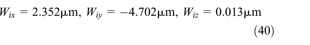
Since the milling depth is relatively small, the cutting force can be regarded as the resultant force acting on the tip point. According to the empirical formula, the milling forces in three directions are:

As shown in Figure 2, the theoretical i-th milling point in the workpiece coordinate system is
According to the model of the cutting force and the machining error in Section 3. The deformation offset caused by the tool deformation at this point is

The machining error due to the deformation of the cutting process system at this point is

The machining error at this point caused by the cutting force can be expressed as:

The position coordinates of the actual cutting point are corrected to:

In order to simulate the roundness tolerance value, the method is to extract the contact trajectories of the tool and the outer circle with a diameter of 109 mm.The actual spatial distribution of the contact points is shown in Figure 8(a). In the XY-direction view, the error is magnified 1000 times, and the discrete points look like an approximate circular trajectory as shown in Figure 8(b). The roundness tolerance zone is the area between two concentric circles, and the roundness value is the difference in radius between two concentric circles. Figure 8(c) shows the distance of all discrete points relative to the center of the fitted circle. The roundness tolerance value for this simulation is 0.031 mm, which is the height of the area. The simulated roundness tolerance value exceeds the requirement, so the end error range needs to be adjusted, see Table 5 for cutting parameters

Roundness simulation result: (a) the spatial distribution of the discrete points, (b) XY view according to the magnified error and (c) distribution of distances from discrete points to the center of the fitted circle.
The cutting parameters.

Based on the assumption that the variation ranges of the translational error and the rotational error should be consistent. The independent constraints and comprehensive constraints corresponding to the roundness tolerance include two precision parameters
After the calculation by MATLAB, the final adjustment end pose error range is:

The simulation result after adjusting the end pose error range is shown in Figure 9. All distances fall within the area of 109.003–109.020 mm. The roundness tolerance value for this simulation is 0.017 mm and meets roundness tolerance requirement.

The simulation result after adjusting the end pose error range.
Modeling of the outer square side straightness tolerance item
According to the requirements of the outer square side straightness tolerance, the end pose error range estimated by Section 2 is:
The selection of machine tool parameters, tool parameters and cutting parameters for processing are the same as the previous part.
Schematic diagram of the outer square processing as shown in Figure 10. The theoretical i-th milling coordinate point is

Schematic diagram of square processing.
The machining error due to tool deformation at this point is
The machining error due to the deformation of the machine tool transmission system at this point is

The machining error caused by the cutting force can be calculated by equation (35).
The position coordinates of the actual cutting point can be corrected by equation (36).
In order to simulate the straightness tolerance value, the method is to extract the contact trajectories of the tool and the outer square side. The spatial distribution of the actual contact points is shown in Figure 11(a) through the discrete trajectory. The distribution of discrete points in the XY view is shown in Figure 11(b). All discrete points fall in the two XZ planes with distance of 0.014 mm. The straightness tolerance value for this simulation is 0.014 mm and meets the straightness tolerance requirement. So the end pose error range corresponding to this straightness tolerance term does not need to be adjusted.

Straightness simulation result: (a) the spatial distribution of the discrete points and (b) XY view.
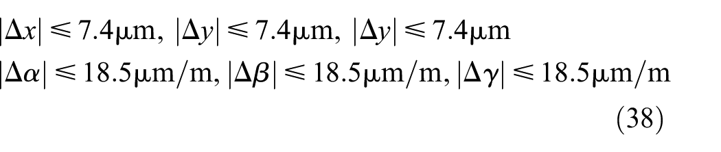
In the same way, this paper simulates the remaining geometric tolerance items of the small size contour processing test piece and adjusts the corresponding end pose error ranges. The range of design variables obtained after adjustment are shown in Table 6. It can be seen that as long as
Design variable range after adjustment.

Conclusions
Aiming for the problem that the precision design index of the machine tool is difficult to determine reasonably, this paper presents a mapping model of the workpiece geometric tolerance and CNC machine tool end pose error considering structure distortion of cutting process system, and takes the small size contour processing test piece as an example to illustrate the application process of the model. The following conclusions can be drawn.
This mapping model is systematic and universal. It can reasonably determine the accuracy design index according to the different geometric tolerance requirements of parts, the different design rigidity of the machine tools and the different process parameters. Therefore, for the production of specific parts with a certain scale, machine tool manufacturers can design machine tools with corresponding end accuracy index. This method can not only make the processed parts meet the accuracy requirements, but also reduce the manufacturing cost of the machine tool.
In addition to the determination of machine tool accuracy design specifications, the proposed mapping model can be used to determine whether the existing machine tool can process qualified workpiece, or to the tolerance optimization design of the workpiece.
The cutting process system will produce a degree of deformation under the cutting forces. Only when the cutting force changes, this elastic deformation will affect the geometric tolerance of the workpiece, such as when processing curved surfaces. However, the processing error caused by this elastic deformation will affect the dimensional tolerance of the workpiece.
This model establishes a numerical relationship between the limit of the machine tool end error and the limit of the geometric tolerance by the Monte Carlo method. The range of the machine tool end pose error obtained through adjustment is relatively strict. Since the machine tool end errors are unevenly distributed in the machining space, the design index can be relaxed appropriately in actual applications.
Footnotes
Handling Editor: James Baldwin
Declaration of conflicting interests
The author(s) declared no potential conflicts of interest with respect to the research, authorship, and/or publication of this article.
Funding
The author(s) disclosed receipt of the following financial support for the research, authorship, and/or publication of this article: This work was supported by the Chinese National Science and Technology Major Project [grant number 2018ZX04033001].