
Abstract
This paper is concerned with trajectory planning for unmanned aerial vehicle in a three-dimensional complex workspace. Biogeography-based optimization algorithm is widely used in solving practical problems because of its fewer parameters, fast convergence rate, and good global optimization ability. In this paper, some improvements, modifying migration and mutation operations are made on the biogeography-based optimization algorithm to make it suitable for solving the trajectory planning problem. The optimal trajectory obtained by the improved algorithm can be used to generate the reference trajectory. Then, a control scheme of unmanned aerial vehicle based on the Lyapunov theory and radial basis function neural network is formed to track the reference trajectory. The improved trajectory algorithm generates the shortest trajectory and the time consumption is the lowest. Finally, the designed control scheme makes the unmanned aerial vehicle track the different trajectories quite well, the effectiveness of it can be illustrated by algorithm accuracy and electricity consumption.
Introduction
Unmanned aerial vehicle (UAV) is often seen for reconnaissance, search, and rescue missions in dangerous areas because of its high mobility, low risk, and low cost.1,2 In order to ensure the efficiency and safety of UAV in the task completion, it is usually necessary to estimate an optimal flight trajectory before a mission execution. The trajectory planning for UAV in complex environments to avoid a series of obstacles is really a challenging problem. For these reasons, UAV trajectory planning has become a research hotspot.1–6
Samaniego et al. 7 regarded the space of UAV flight as a discrete adaptive grid with minimum step size, and used cost response algorithm and recursive calculation to conduct trajectory planning, which reduced the response time, Lupascu et al. 8 extended the square in two dimensions to the cube in three dimensions for trajectory planning, and demonstrated the feasibility of the algorithm. Contreras-Cruz et al. 9 trajectory planning in a static environment using artificial bee colony algorithm was proposed. Firstly, artificial bee colony algorithm was used to explore the local environment, and then evolutionary algorithm was used to obtain the optimal trajectory. Li et al. 10 used the balance strategy to make an improvement on the artificial bee colony algorithm, and collected the convergence information in the iterative process to control the exploration accuracy, so as to achieve a balance between local and global information. Particle swarm optimization algorithm with dynamic adjustment of inertia weight (WLIPSO) used in Lu et al. 11 initialized a swarm of particles with a random solution. The cooperation and competition ideas were introduced to update its speed and it found the optimal solution by searching for the personal best and the global best. However, in the late stage of the convergence, the convergence speed becomes slow, all particles tend to be the same and lose diversity. When the algorithm converges to a certain degree, it cannot be further optimized and the accuracy it can achieve is not high. Biogeography-based optimization with covariance matrix based migration (CMM-BBO) 12 is a novel evolutionary algorithm. The covariance matrix based migration operator combined with the original migration randomly, thus the population diversity is increased. CMM-BBO can get the optimal solution of the shortest trajectory, but it is inefficient because it traverses many nodes and performs many repeated operations. The above algorithms have some disadvantages, with the expansion of the planning area, their computational complexities will increase exponentially, resulting in a “combinatorial explosion,” and they are prone to fall into local optimal solutions, which needs to be avoided. Compared with these algorithms, the improved BBO algorithm can deal with the uncertainty in trajectory planning more effectively and improve the reliability of trajectory planning and the stability of the system.
Biogeography-based optimization (BBO) algorithm, proposed in Simon, 13 is a global optimization algorithm that studies the distribution of organisms in geographical areas. It uses migration operation to realize information sharing among solutions (habitats) and uses mutation operation to enrich the population diversity in habitats. 14 It describes the migration, formation, and extinction of species by the mathematical model based on biogeography. 15 The improved BBO algorithm is similar to particle swarm optimization (PSO) algorithm, ant colony optimization algorithm, and genetic algorithm, but it has fewer designed parameters, low computational complexity, and strong optimization performance.3,13,16,17
According to the grid-based workspace modeling algorithm in Zhang et al., 18 Islam et al., 19 and He et al., 20 the UAV’s workspace is divided into a series of small blocks by using grids through the three-dimensional space, and the vertices of each block are selected as trajectory nodes. Mark these nodes as collision and collision-free nodes by determining whether they are in obstacles or not.21,22 Simply select a series of available trajectory nodes (collision-free nodes) in a certain order and put them into a trajectory node list, that list consists of some available trajectories. Each available trajectory can be regarded as a habitat in the biogeography algorithm, and its nodes can be regarded as suitability index variables (SIVs) 23 of the habitat. The habitat suitability index (HSI) 24 of each habitat can be obtained by taking its nodes as parameters into the cost function calculations. According to the obtained HSIs, the immigration rate, emigration rate, and mutation probability corresponding to each habitat can be calculated, which can be used for the migration operation and mutation operation.25,26 Finally, the optimal trajectory is generated. In particular, an improved migration and mutation operation is proposed in section 2.D for UAV trajectory planning. In addition, WLIPSO and CMM-BBO algorithm are used to complete the task of the UAV trajectory planning in the same workspace, and then compared with the proposed algorithm.
The optimal trajectory generated by the proposed biogeography algorithm can be used to generate the flight reference trajectory for UAV. Then, a fixed-wing UAV mathematical model under external interference is constructed and selected as the research object. 27 Finally, according to the generated reference trajectory, a robust controller designed based on Lyapunov stability theory and radial basis function neural network (RBFNN)28,29 is used for the fixed-wing UAV tracking the reference trajectory.
Our main contributions are summarized as follows:
In this paper, the algorithm of setting collision nodes is used in the 3D workspace to model the UAV operation environment, which effectively improves the operation efficiency of the trajectory planning algorithm in the 3D workspace.
The novel trajectory planning algorithm based on biogeography algorithm improves the migration and mutation operations compared with the original biogeography algorithm, making it more suitable for UAV trajectory planning.
According to the trajectory generated by the improved BBO algorithm proposed in this paper, an interpolation algorithm based on time step is designed, which can convert the discrete points in the workspace to a relatively continuous trajectory, and can effectively realize the UAV’s accurate tracking of the reference trajectory after combining with the designed UAV control scheme.
The arrangement of this paper is made as follows: In section 2, the improved trajectory planning algorithm based on BBO in the 3D workspace is presented. We give the mathematical model of the UAV in section 3. The control scheme of UAV with the planned trajectory is proposed in section 4. Section 5 presents the experimental details and shows the effectiveness of the improved BBO algorithm and the control scheme. We give a conclusion in section 6.
The improved trajectory planning algorithm based on BBO in three-dimensional environment
For ease of expression, the following notations are exploited in this paper:
There exists a pseudo inverse in a non-full rank matrix
BBO is a biology evolutionary algorithm using biogeographic dynamic models and ideas that describe the movement of species from habitat to habitat in an ecosystem and how species are created or lost. 31 In BBO, each habitat resembles an island in the sea, is regarded as a possible solution and has a HSI to test the suitability and the priority of the habitat. Other aspects, for example, plant and animal diversity, rainfall capacity, etc., which characterize HSI are called SIVs.31,32
In the following proposed BBO based trajectory optimizing process, the habitat is considered as the trajectory in the trajectory planning, a SIV of each habitat as a route node, the HIS of each habitat as the cost function.
The construction of the UAV’s workspace
The first step of the vehicle’s trajectory planning in three-dimensional space is to construct the vehicle’s work environment in a meaningful way. According to He et al. 20 and Garrido et al., 33 the grid-based workspace modeling algorithm is introduced to describe the vehicle’s workspace. As shown in Figures 1 and 2, this algorithm cuts the UAV’s workspace into nx × ny × nz blocks (nx, ny, and nz are the number of cutting layers on the x, y, and z axes, respectively), the vertexes of each block are selected as the trajectory node, and the nodes in obstacles are defined as collision nodes, 34 which means that UAV cannot pass through them. On the contrary, UAV can plan a trajectory from start to end by constructing a list only containing collision-free nodes.

The UAV’s workspace in three-dimensional workspace.

The UAV’s constructed workspace in three-dimensional space (red stars and blue dots represent collision nodes and collision-free nodes, respectively).
A trajectory generation algorithm based on the constructed workspace
Before operating BBO algorithm, some initial trajectories need to be generated randomly so that they can be used as initial habitats in BBO to facilitate the formation of optimal trajectories by immigration, mutation, and other operations.
As shown in Figure 3, according to the construction algorithm of UAV’s workspace described above, the node where the UAV is currently located can be marked as node(i), the i-th node in UAV’s constructed workspace,

The adjacent nodes of node(i) in x, y, and z axis.
The steps of the trajectory generation algorithm are as follows:
Step 1. A trajectory node list PL is initialized as an empty list; the iteration times IR is initialized as zero, the maximum iteration times is set as IRmax; the current node and goal node is initialized as node(i) and node(j),
Step 2. Firstly, the node(i) is selected into PL; Then, judging whether node(i) or node(x) is a collision node, if it is, return error information, else, obtain the three-dimensional position of node(i) and node(j), which is
Step 3. Firstly, the collision nodes in VS is eliminated; then, one node in VS is randomly selected as the next position of UAV; particularly, an adjacent node of node(i) that is not collision node is randomly selected as the next position of UAV, when there is no node in VS. The randomly selected node is set as node(k), and IR = IR + 1.
Step 4. To avoid duplicate nodes in PL, node(i) is set as a collision node, then the selected node in Step 3 is set as the current node by letting i = k. If three-dimensional position of the current node is equal to goal node or IR > IRmax, save the trajectory list PL and return success information, else, skip to Step 2.
To illustrate the trajectory generation algorithm visually, all available trajectories generated from the current node to the goal node are shown in Figure 4.

The trajectories generated by the proposed trajectory generation algorithm from the current node to the goal node.
Cost function
In the process of UAV trajectory planning, choosing an optimal trajectory is the ultimate goal. Usually, there is a cost function to measure whether the current trajectory is optimal. If the algorithm has a small value of cost function, then the computational complexity is small. Compared with other trajectories, the generated trajectory with the smallest value of cost function will be considered as the optimal trajectory. 5 The cost function is defined as follows:

In the cost function,
The term related to the length of the planned trajectory is represented as follows:

Where
The term related to the smoothness of the planned trajectory is represented as follows:

Where
The migration and mutation operation
Migration
The i-th habitat PL
i
(a trajectory node list of the i-th habitat) and j-th habitat PL
j
(a trajectory node list of the j-th habitat) are selected for immigration and emigration operation respectively,
Mutation
The i-th habitat PL i is selected for mutation operation. Firstly, a node node(m) that is not a collision code is randomly selected from the UAV’s workspace in Figure 2 and use it as the start node to generate a new trajectory to the goal node by using the trajectory generation algorithm, then, similarly, node(p) is randomly selected from PL i and use it as the start node to generate a new trajectory to the node(m). In the end, clear the node(p) and all subsequent nodes in PL i and put the two new generated trajectories into PL i .
An improved BBO algorithm
Each habitat has its specific emigration rate

Where
Now, the variable
The mutation probability

Where
The steps of the improved BBO algorithm are summarized as follows:
Step 1. The trajectory generation algorithm proposed in section 2.2 is used to randomly generate Np trajectories, which are used as the initial habitats, between the start node and the goal node. These parameters are initialized: the max emigration rate E, the max immigration rate I, the probability
Step 2. The cost function
Step 3. If
Step 4. If NR > NRmax, save the optimal trajectory and return the success information, else, skip to Step 2.
The mathematical model of the fixed-wing UAV
Usually, the UAV’s motion in three-dimensional space needs to be transformed among three coordinate frames: body coordinate frame, inertial coordinate frame, and airflow coordinate frame, expressed in letters n, b, w, respectively.36–38 The relationships between three coordinate frames are shown in Figure 5.

The fixed-UAV in three-dimensional space.
Firstly, some definitions are given as:

The coordinate transform matrices


The coordinate transform matrix
Let
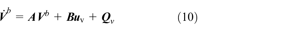

The complete form of
The external disturbances and model uncertainty issues are considered, equations (10) and (11) are rewritten as:
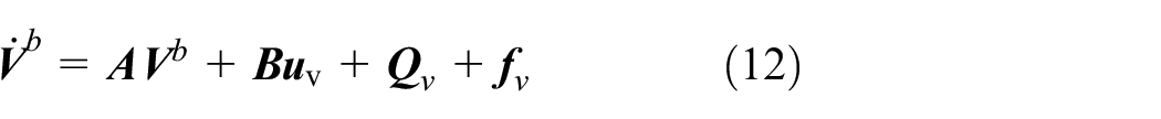
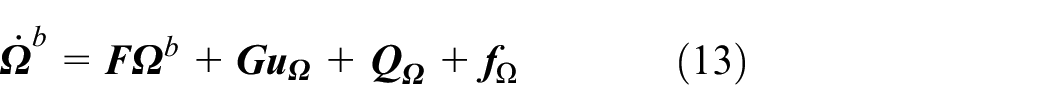
Where
The control scheme of UAV with the planned trajectory
According to the trajectory optimization algorithm proposed in section 2.E, an optimal trajectory PL connecting the initial node and the goal node is obtained. In particular, this trajectory consists of a series of trajectory nodes.
The reference trajectory and its derivative required by UAV is as follows:
Step 1. The start node in PL is initialized as the current node node(i), the air speed of UAV is set as
Step 2. The time it takes to fly from the current node(i) to the following node(i + 1) is designed as


Step 3. The time T is updated by


The control scheme for UAV’s attitude and position is designed as follows:
Let

A Lyapunov function is given as follows:

According to equation (12), the derivative of

Where
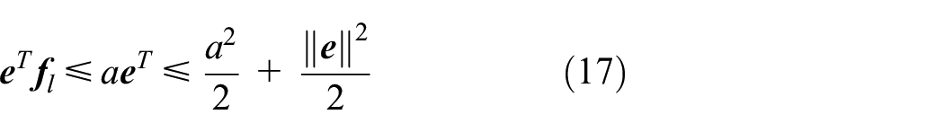
Use equation (17), equation (16) is rewritten as:

To complete the UAV’s task, the desired controller

Let

Use Lemma 1, one can obtain that:

where
Then, a redesigned Lyapunov function is generated as:
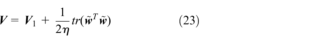
By combining equations (12), (17), and (22), the derivative of equation (23) is obtained as:
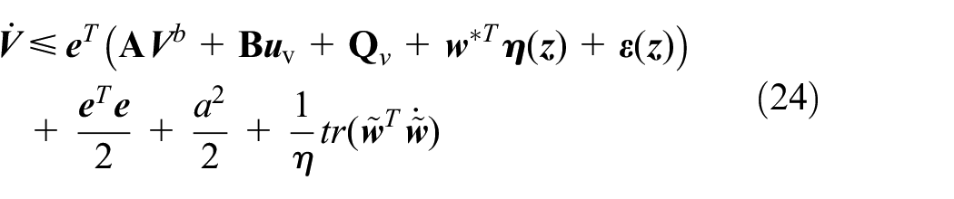
According to Lemma 2, the following one is obtained:

Use equation (25), equation (24) is rewritten as:
To finish the control task, the controller is redesigned as:

Where

Substitute equations (27) and (28) into equation (26), yields:
Based on the fact that 22 :

The following result is obtained:

So, equation (29) is rewritten as:

Where
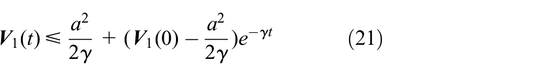
Use Lemma 1, the following one can be obtained:

From it one can conclude that the trajectory tracking error can become very small in the situation of selecting the suitable parameters and choosing RBFNN to estimate the unknown disturbance.
Similarly, the controller

Where
To verify the RBFNN’s performance of estimating the external disturbance, the contrasted controllers without RBFNN of equations (27) and (34) are set as:


Simulation results
The experiment is conducted on a personal computer of Inter Core I7 eight-core processor, 16 GB memory, 1T hard disk, and MATLAB R2018a is used for simulation analysis. The effectiveness of the proposed trajectory planning algorithm and UAV control scheme is verified in this section. The specific simulation process is represented as follows: Firstly, the map in Figure 1 is selected as the UAV’s workspace, the coordinates
The simulation results of trajectory planning using WLIPSO, CMM-BBO, and the improved BBO algorithm can be obtained as follows. The optimal trajectory length obtained by WLIPSO is 108 m, and it takes 7.1 s to solve the trajectory planning problem. The CMM-BBO algorithm is 99 m and it takes 6.7 s. The improved BBO is 94 m and it takes 4.8 s. After 30 iterations, the values of the cost function of WLIPSO, CMM-BBO, and improved BBO are 93.5, 90.3, and 88.2, respectively. The improved BBO achieves the lowest value of cost function, the computational complexity is the lowest compared with other two algorithms. After obtaining the optimal path quickly, the UAV follow the optimal path to complete the specific task. It can be concluded that the improved BBO based trajectory planning algorithm has good performance, and the trajectories planned by these algorithms in three-dimensional workspace are shown in Figure 6.

Trajectory planning using different algorithms.
As shown in Figures 7 and 8, the improved BBO based trajectory planning algorithm is used to find an optimal trajectory connecting the start node and the goal node in the complex working environment. The trajectory generated by the improved BBO is selected as the reference trajectory. From the two-dimensional plane and the three-dimensional plane, it can be seen that the actual flight trajectory of the UAV almost coincides with the reference trajectory. From Figure 9, it can be seen that the control scheme without RFBNN is bad in following the reference trajectory. The reason why the proposed control scheme has good tracking effect is that it can better compensate for the compound interference terms and eliminate the influence of various interferences in the flight process.
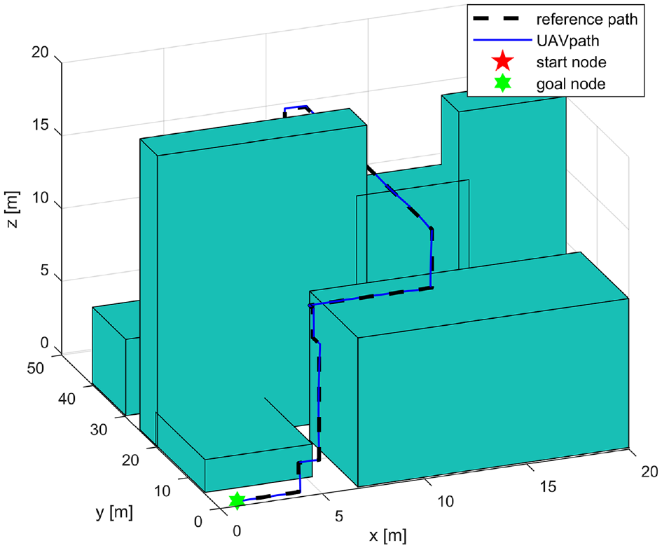
Trajectory planning and following in three-dimensional workspace.
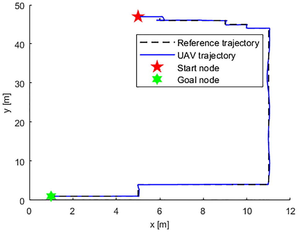
The vertical view of UAV trajectory tracking.

The vertical view of UAV trajectory tracking without RBFNN.
The trajectory tracking effects of different methods can be seen from Figures 10 to 15. By using the proposed control scheme, the UAV can track the trajectory quite well in three different situations. The position deviation and the attitude deviation are small in all tracking process. The algorithm accuracies of positions generated by WLIPSO, CMM-BBO, and improved BBO are 96.30%, 96.86%, and 96.48%, respectively. The average algorithm accuracy is 96.55%. The electricity consumption is a crucial problem for UAV tracking. The time consumption of UAV in tracking the trajectories generated by WLIPSO, CMM-BBO, and improved BBO are 20.40, 18.80, and 18.20 s, respectively. Among the three algorithms, the trajectory length and time consumption of the proposed algorithm is the lowest, and the electricity consumption of it is the lowest.

UAV’s positions tracking of improved BBO.

UAV’s attitudes tracking of improved BBO.
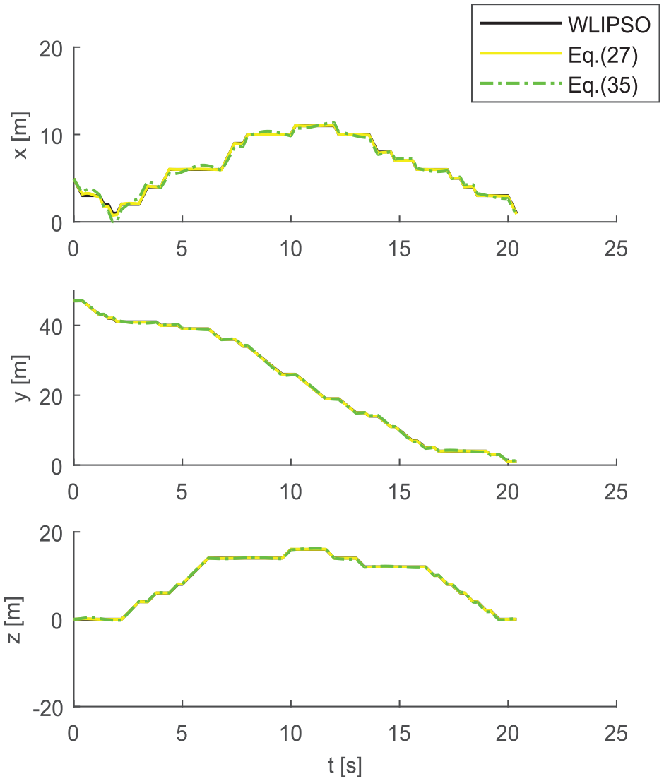
UAV’s positions tracking of WLIPSO.

UAV’s attitudes tracking of WLIPSO.
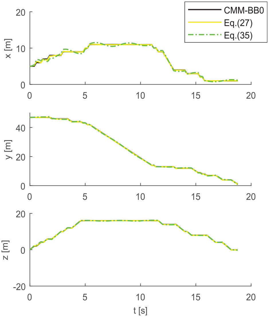
UAV’s positions tracking of CMM-BBO.

UAV’s attitudes tracking of CMM-BBO.
To evaluate the good tracking performance of the designed controller, controllers with and without RFBNN are compared. The tracking effects of positions and attitudes in three directions are illustrated from Figures 10 to 15. The controllers with neural network proposed in equations (27) and (34) are used to track the different trajectories, the control effects are better than controllers without neural network proposed in equations (35) and (36). That is because the neural network used in this paper can accurately estimate the unknown external disturbance. From Figures 16 to 17, it can be concluded that the estimated values are close to the actual values, the neural network has good estimation ability.

The disturbances in equation (12) and its estimates.

The disturbances in equation (13) and its estimates.
Conclusions
This paper proposes an off-line trajectory planning algorithm and a robust trajectory tracking control scheme for fixed-wing UAV. In this paper, an improved trajectory planning algorithm based on BBO is proposed to generate an optimal trajectory connecting the start node and the goal node for obstacle collision avoidance. By comparing with WLIPSO and CMM-BBO algorithm, it is concluded that this algorithm has certain advantages in UAV trajectory planning. A robust controller with RBFNN to estimate unknown disturbances is proposed to track the trajectory generated by three algorithms. Compared with other two algorithms, the improved BBO algorithm and the designed control scheme generate the optimal trajectory in the subjective and objective aspects. In the following work, the reduction of the algorithm complexity will be considered.
Footnotes
Appendix
Handling Editor: James Baldwin
Declaration of conflicting interests
The author(s) declared no potential conflicts of interest with respect to the research, authorship, and/or publication of this article.
Funding
The author(s) disclosed receipt of the following financial support for the research, authorship, and/or publication of this article: This work was supported in part by Sichuan Science and Technology Program under Grant 2017GZ0303, in part by Fund Project of Sichuan Provincial Academician (Expert) Workstation under Grant 2016YSGZZ01, and in part by Special Fund for Training High Level Innovative Talents of Sichuan University of Science and Engineering under Grant B12402005.