
Abstract
In order to improve the trajectory smoothness and the accuracy of lane change control, an adaptive control algorithm based on weight coefficient was proposed. According to lane change trajectory constraint conditions, the sixth-order polynomial lane change trajectory applied to intelligent vehicles was constructed. Based on the vehicle model and the model predictive control theory, the time-varying linear variable path vehicle predictive model was derived by combining soft constraint of the side slip angle. Combined with fuzzy control algorithm, the weight coefficient of the deviation of the lateral displacement was dynamically adjusted. Finally, the FMPC (model predictive controller based on fuzzy control) and MPC controller were compared and analyzed by co-simulation of CarSim and Simulink under different speeds. The simulation results show that the designed FMPC controller can track the lane change trajectory better, and the controller has better robustness when the vehicle changes lanes at different speeds.
Keywords
Introduction
Intelligent vehicle is a new generation integrated system integrating Internet, communication, intelligent control, environment awareness and path planning.1–4 The application of intelligent driving technology greatly improves the active safety, ride comfort and handling stability of automobiles. 5 At present, it has become the focus of research in various countries and an important part of intelligent transportation system. Active vehicle lane change is one of the common behaviors in daily driving. A safe and effective lane change trajectory and a smooth and comfortable lane change process have become an important indicator for evaluating the ability of intelligent driving vehicles to actively change lanes. 6
At present, path planning algorithms can be divided into dynamic search algorithms and geometric model algorithms.7–11 Path planning based on dynamic search originated from robotics. Through the analysis of the surrounding environment and the constraints of conditions, the optimal target path was programmed dynamically. 12 The classical dynamic search algorithm includes Dijkstra algorithm, A* algorithm, RRT algorithm, V-graph algorithm and so on.13–20 Although these algorithms have good planning and solving speed, they are easy to fall into the local optimal solution, and the path planning effect need to be improved. Neural network algorithm, genetic algorithm, ant colony algorithm, etc., need a lot of iterative operations, and the current vehicle hardware conditions are difficult to meet the requirements.21–24 Path planning based on geometric model includes cosine trajectory, circular trajectory, isokinetic trajectory, trapezoidal acceleration trajectory, polynomial trajectory.15,25 These trajectory models are intuitive, accurate, and have a small amount of calculation. Therefore, they are widely used. 26 Among them, Nelson 27 proposed a fifth-order polynomial lane change trajectory model to ensure the real-time performance and smoothness of lane change trajectory through multiple constraints. However, the curvature change rate of the trajectory model at the end of lane change may not be zero, which may lead to lateral instability. On the basis of Nelson, Taehyun Shim 28 added a sixth-order variable in consideration of the minimum travel distance and collision avoidance conditions, but the process of determining the highest-order coefficients of its lane change trajectory model is more complicated and the amount of calculation is large. Therefore, in order to improve the calculation efficiency and the handling stability of the vehicle during lane change, a sixth-order polynomial lane change trajectory is proposed on the basis of considering the constraints of the curvature change rate at the end of the lane change.
The purpose of trajectory tracking is to allow the vehicle to follow the planned path. The control method is to obtain the corresponding control parameters through the constraints of vehicle kinematics and dynamics. 29 Commonly used control algorithms include PID control algorithm, fuzzy control algorithm, sliding mode control algorithm, LQR control algorithm.30–32 These algorithms respond slowly to changes in the vehicle’s driving environment, so the accuracy of trajectory tracking is affected to some extent. The model predictive control algorithm can predict the vehicle’s motion state within a certain period of time according to the vehicle’s current motion state. 33 Moreover, multiple targets can be constrained at the same time, so that the optimal control parameters can be solved within a limited time period. 34 The weight coefficient of the objective function of the traditional model predictive control algorithm is usually taken as a fixed value, but in actual use, the control system needs to adapt to different working conditions to improve the accuracy of control tracking. Therefore, in this paper, based on the linearized time-varying predictive controller, the FMPC controller is designed, and the fuzzy control algorithm is used to dynamically adjust the weight coefficient of the lateral displacement deviation to improve the accuracy and robustness of the control system. Finally, the FMPC and MPC controller were compared and analyzed by co-simulation of CarSim and Simulink under different speeds.
The main contributions of this paper are as follows:
A sixth-order polynomial lane change trajectory is designed and compared with the fifth-order polynomial lane change trajectory.
A FMPC (model predictive controller based on fuzzy control) controller is designed, and the FMPC and MPC controller were compared and analyzed by co-simulation of CarSim and Simulink under different speeds.
Vehicle lane change trajectory planning
When the vehicle is in danger of collision with the vehicle in front, if the side lane change conditions permit, the collision can be avoided by active lane change. As shown in Figure 1, vehicle A is driving at a higher speed

A scenario of vehicles actively changing lanes to avoid collisions.
When designing a lane change trajectory, both the comfort of the lane change process and the handling stability must be considered. In the planning of commonly used fifth-order polynomial lane change trajectory, constraints on the position and velocity of starting and ending points, as well as constraints on the curvature during lane change have been taken into account, but the influence of the rate of curvature change at the end of lane change has not been taken into account. Therefore, on the basis of the fifth-order polynomial lane change trajectory, the new trajectory is constrained as shown in Table 1.
Constraints of lane change trajectory.

Where
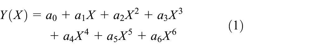
Under the constraints of Table 1, a sixth-order lane change trajectory proposed in this paper is shown in equation (1).
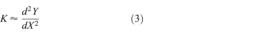
The curvature

Since the vehicle changes
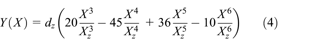
When the constraint conditions 1, 2, and 3 are satisfied, the lane change trajectory is shown in equation (4).
If the curvature reaches its maximum at

Assuming that

In order to meet the condition 1, the longitudinal distance of the lane change trajectory is as short as possible, so

At the speeds of 54, 72, and 108

Vehicle trajectory changes at different speeds.
In Figure 2, the dotted line represents the vehicle’s fifth-order polynomial lane change trajectory at different vehicle speeds, and the solid line represents the vehicle’s sixth-order polynomial lane change trajectory at different vehicle speeds. The
Vehicle dynamics modeling
Vehicle dynamics model is the basis of trajectory tracking and model prediction, but complex dynamics model will increase the difficulty of calculation and reduce the convergence speed. Therefore, the following assumptions are made when establishing vehicle dynamics model: 28
The vehicle runs on a smooth road without obvious road roughness, ignoring the influence of vertical force.
The suspension and body parts are a rigid body without relative motion.
The transmission ratio of the steering system is fixed, and the angle input can act on the wheel directly.
The effects of aerodynamics are ignored, and load transfer is not considered.
Under the above assumptions, a three-degree-of-freedom vehicle model as shown in Figure 3 is established.

Three-degree-of-freedom vehicle model.
In Figure 3,
Considering longitudinal, transverse and yaw motions, the vehicle dynamics equation is established:


Further expansion, we can get the following:


where
In the case of small side slip angle and slip ratio, the longitudinal force and lateral force of front and rear tire can be described by linear relationship. 35 Therefore, it can be obtained that:


where,
Under the condition of small side slip angles, the side slip angles of front and rear wheels can be approximately expressed as follows:


The longitudinal slip rates of front and rear wheels are follows:


where
Substituting equations (14) to (19) into equations (8) to (10), ignoring the influence of front-wheel driving force on the vehicle’s yaw motion (


The following equation of state can be obtained from equations (22) to (26) of vehicle dynamics equation:

where,
Design of linear time-varying model predictive controller
Derivation of linear time-varying model predictive controller
When tracking the lane change trajectory, under the premise of ensuring the stability of the vehicle, the front wheel angle is controlled. In order to improve the prediction accuracy and solution speed, the nonlinear model needs to be linearized and discretized.
Assuming that the state vector of the system at the current moment is


where,
Within the predictive horizon, the system can obtain the reference state vector


where,


If the control vector


where,
The output of equations (32) and (33) in the predictive horizon

where,
In order to ensure the stability of the vehicle during lane change, the slip angle of the tire should be controlled within a certain range. Therefore, it is necessary to carry out soft restraint on the slip angle of the tire, so as to improve the steering stability and the ability of lateral skid prevention. In order to ensure that the equation can be solved with soft side constraints, relaxation factor

where,
If the control vector

where,
The output of equations (36) in the predictive horizon

where,
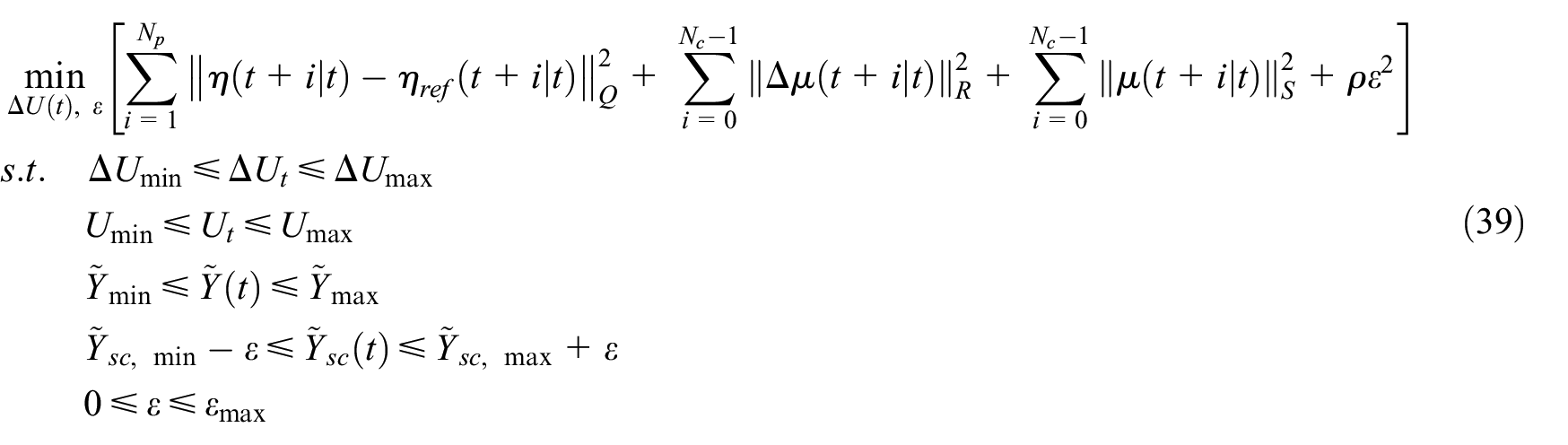
Equations (34) and (37) are the prediction models of the lane change trajectory of the vehicle. According to the above model and relaxation factor, the objective function of rolling optimization can be set as follows:

Where, the first term reflects the requirement for the tracking ability of the reference trajectory, and the second term reflects the requirement for the smoothness of the lane change process, and the third term reflects the requirement for the control vector. The fourth term is the relaxation factor, which is used to prevent the objective function from no solution in the control horizon. The constraints of the objective function are as follows:
Dynamic adjustment of weight coefficient
In the theory of model predictive control, the weight coefficient of the objective function of the traditional algorithm is usually taken as a constant value. But in practice, the fixed weight coefficient may reduce the accuracy and robustness of the control system due to different working conditions. Therefore, in order to improve the accuracy of tracking the lane change trajectory, it is necessary to dynamically adjust the weight coefficient of the deviation of the lateral displacement. When the average deviation

The degree of membership of
As shown in Figure 5, when
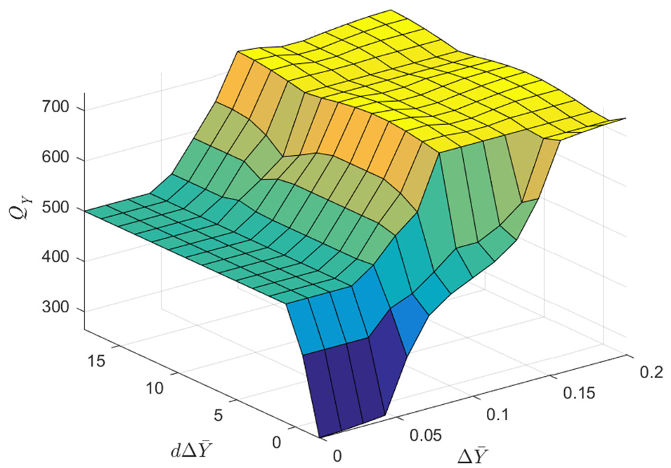
The relationship of
The fuzzy control regulation rule of the weight coefficient
The fuzzy control regulation rule of

S: small; M: medium; L: large; N: negative; PS: positive small; PL: positive large.
When
Simulation design and verification
The block diagram of the control system
CarSim and Simulink are used to establish the experimental simulation platform to realize the design and verification of the model predictive controller. The block diagram of the control system is shown in Figure 6.

The block diagram of the control system.
In this paper, the model predictive controller based on fuzzy control is called FMPC.
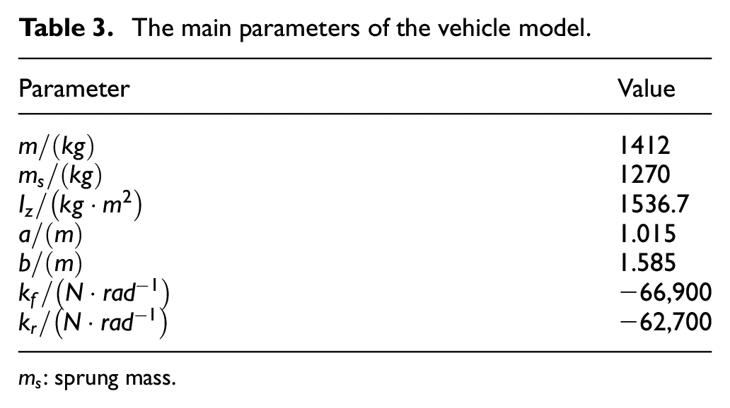
Vehicle parameters
The main parameters of the vehicle model are shown in Table 3.
The main parameters of the vehicle model.
The main parameters of the controller
Sampling period:
Predictive horizon and control horizon:
Weight coefficient matrix:
Constraints:
Reference trajectory:

Simulation analysis
In order to verify the effectiveness and robustness of the control algorithm, the vehicle controller based on FMPC and MPC is compared and analyzed. The forward travel speeds of 54, 72, and 108
At different speeds, the tracking reference curve and actual lateral displacement curve, the deviation of tracking reference curve and actual lateral displacement curve, the maximum deviation of tracking reference and actual lateral displacement curve are shown in Figures 7(a)–(c) and 8(a)–(c), and Table 4, respectively.
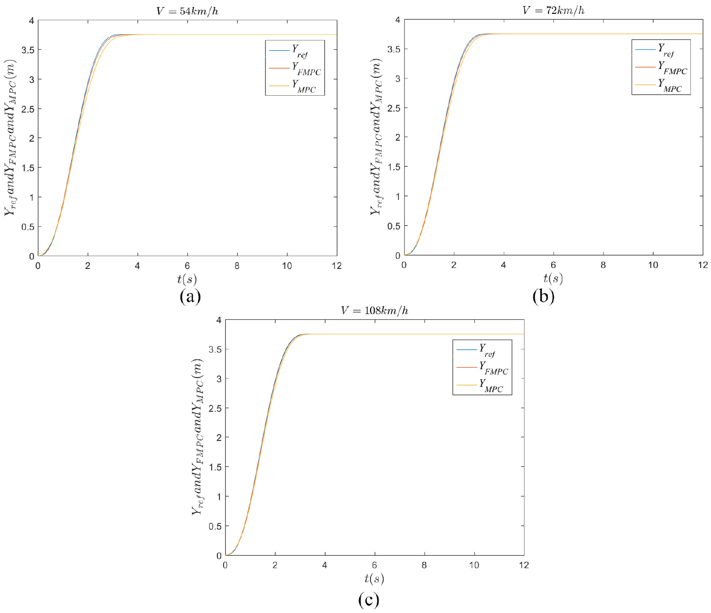
The tracking reference curve and actual lateral displacement curve.

The deviation of tracking reference and actual lateral displacement curve.
The maximum deviation of tracking reference and actual lateral displacement curve.
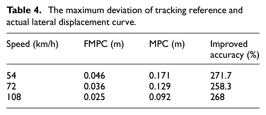
From Figures 7(a)–(c) and 8(a)–(c), and Table 4, it can be seen that when the vehicle changes lanes at a speed of 54
At different speeds, the reference curve and the actual curve of the front wheel angle, the deviation between reference angle and actual angle of the front wheel are shown in Figures 9(a)–(c) and 10(a)–(c).

The reference curve and the actual curve of the front wheel angle.

The deviation between reference angle and actual angle of the front wheel.
From Figures 9(a)–(c) and 10(a)–(c), it can be seen that, at different speed, the jitter of the front wheel angle based on the MPC controller is relatively large, the deviation between reference angle and actual angle of the front wheel is large, and the chatter of the deviation is relatively severe. However, the front wheel Angle curve and the deviation curve based on FMPC controller are relatively smooth at different speeds. When the vehicle speed changes lane at 54 and 72
At different speeds, the reference yaw angle curve and the actual yaw angle curve, the deviation between the reference yaw angle and the actual yaw angle, the peak deviation between the reference yaw angle and the actual yaw angle are shown in Figures 11(a)–(c) and 12(a)–(c), and Table 5, respectively.

The reference yaw angle curve and the actual yaw angle curve.

The deviation between the reference yaw angle and the actual yaw angle.
The peak deviation between the reference yaw angle and the actual yaw angle.
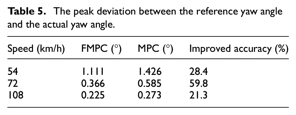
From Figures 11(a)–(c) and 12(a)–(c), Table 5 combined with Figures 2 and 9(a)–(c), it can be seen that, at low speed, the longitudinal displacement of vehicle lane change is shorter, and the front wheel angle changes greatly, so the vehicle movement is more violent. Therefore, the deviation between the reference yaw angle and the yaw angle based on the two controllers is large, but it is still within the acceptable range. However, with the increase of vehicle speed, the longitudinal displacement of lane change becomes larger, the lane change time is longer, the change of front wheel angle is relatively small, and the vehicle movement is comparatively gentle. At this time, the deviation between the reference yaw angle and the yaw angle based on the two controllers is relatively small. When the vehicle changes lane at 54
At different vehicle speeds, the sideslip angle of mass center based on FMPC and MPC controller is shown in Figure 13(a)–(c).

The sideslip angle of mass center based on FMPC and MPC controller.
From Figures 13(a)–(c) and 9(a)–(c), it can be seen that, when the vehicle changes lanes at medium or low speeds, the vibration of the side slip angle of mass center based on MPC controller is more severe due to the large change range of the front wheel angle. While the
Conclusions
In order to improve the trajectory smoothness and the accuracy of lane change control, in this paper, on the basis of the constraints of the curvature change rate at the end of the lane change, a sixth-order polynomial lane change trajectory was proposed, and compared with the traditional fifth-order polynomial lane-changing trajectory. The simulation results show that at the position close to the lane change terminal, the lane change trajectory of the sixth-order polynomial is smoother, which can effectively reduce the vehicle instability during high-speed driving, thus improving the handling stability and passenger’s comfort.
On the basis of the traditional model predictive control algorithm, combined with the soft constraint of the side slip angle, the fuzzy control algorithm was used to dynamically adjust the weight coefficient of the lateral displacement deviation. The designed FMPC controller and MPC controller are simulated and compared under different speed conditions. The simulation results show that, at different vehicle speeds, compared with MPC controller, the designed FMPC controller can better control the vehicle state, and track the planned lane change trajectory more accurately by controlling the front wheel angles. The lane changing process is smoother and more stable. Therefore, the designed FMPC controller has better tracking characteristics and robustness.
In this paper, the design of lane change trajectory and controller was only carried out under the condition of the vehicle changing lanes at a constant speed, and the simulation verification was carried out under fine road adhesion conditions. In the next work, we will further improve the application range of lane change trajectory and controller, and further verify the robustness of the controller under different road adhesion conditions.
Footnotes
Handling Editor: James Baldwin
Declaration of conflicting interests
The author(s) declared no potential conflicts of interest with respect to the research, authorship, and/or publication of this article.
Funding
The author(s) disclosed receipt of the following financial support for the research, authorship, and/or publication of this article: This work was supported by the National Natural Science Foundation of China (No. 51875235), the Fundamental Research Funds for Central Universities (No. 2020JCXK24), National Natural Science Foundations of China (No. 51605215), the National Science Foundations for Post-Doctoral Scientists of China (Nos. 2018M630593, 2019T120450), and the Qing Lan Project.