
Abstract
Through the combination of experimental measurement and CFD (computational fluid dynamics) method, the fluid flow characteristics in the pipe of magnetic capsule robot for intestinal tract are studied. The PIV (particle imaging velocimetry) system is used to measure the fluid flow field around the magnetic-controlled capsule robot under certain translational and rotational speeds, and the rich flow field information (streamline, velocity, and vorticity) is obtained. At the same time, the CFD software is used to calculate the corresponding flow field and the force acting on the capsule robot, and the calculated value is basically consistent with the experimental value. The results show that, driven by the external permanent magnet, the magnetic capsule robot makes corresponding precession movement in the pipe filled with silicone oil, and the movement track is wavy. When the pipe diameter is increased, the fluid streamline around the capsule robot is more stable, the vorticity value is smaller, the resistance and resisting moment of the capsule robot in the forward direction become smaller. The PIV measurement method and CFD method used in this paper can be applied to the fluid flow field measurement and mechanical analysis of the smaller size capsule robot in the liquid environment.
Keywords
Introduction
With the improvement of human living standard, the proportion of gastrointestinal diseases is higher and higher, which has become one of the main reasons for the risk of human health. Minimally invasive surgery is one of the main trends of medical development in the 21st century. The traditional method is to insert the catheter directly into the gastrointestinal tract, which can easily cause harm and pain to human body. Therefore, the research and development of capsule robot which can enter the gastrointestinal tract has become a hot topic.
According to the structure of robots, capsule robots are mainly divided into cylindrical capsule robot, 1 leg capsule robot, 2 outer spiral capsule robot, 3 and inner spiral capsule robot. 4 The cylindrical capsule robot is widely used in practice because of its smooth outer surface, smaller damage and appropriate volume.
According to the driving mode, capsule robots can be divided into internal driven capsule robot and external driven capsule robot. Although the control mode of the internal driven capsule robot is more convenient, the cable will seriously affect its motion flexibility and increase the damage to the intestinal tract. And the micro battery will also increase the capsule volume and limit the power supply time. The external driven capsule robot mainly depends on the external magnetic field, microwave and other energy. However, the driving method of the magnetic field is relatively simple, so it has great advantages in the active control of the capsule robot.
The existing driving methods of the magnetic field are mainly divided into two types: coil method and permanent magnet method. The coil method is to use multiple coils to generate space magnetic field to drive capsule robot. Nguyen et al. have studied the use of five pairs of electromagnetic coils to drive cylindrical capsules with permanent magnets in the pipe for drug delivery. 5 Yuan et al. have designed a driving system composed of eight electromagnetic coil modules to drive the magnetic capsule to move according to the predetermined trajectory. 6 The permanent magnet method is to use the motion of external permanent magnet to drive the capsule robot with internal permanent magnet to make corresponding motion. Mahoney and Abbott have studied the use of the external axial magnetizing cylindrical permanent magnet that is clamped by five degree of freedom manipulator to drive magnetic cylindrical capsule to make corresponding motion. 7 . Li et al. have calculated the space magnetic field around the radial magnetizing ring permanent magnet, and used a manipulator to clamp the external permanent magnet to drive the magnetic cylindrical capsule to make corresponding motion. 8 Pittiglio et al. have used a series manipulator to clamp a single external cylindrical permanent magnet to drive the magnetic cylindrical capsule to make corresponding motion, and proposed a control strategy to reduce the friction between the capsule and the intestinal wall. 9 The equipment used in the coil method has a relative complexity, high cost, cumbersome operation and strong electromagnetic radiation that may causes harm to human body. The biggest advantage of the permanent magnet method is that the control principle is simple, the operation is convenient, and it is easy to commercialize. However, the difficulty lies in controlling the force balance of the external permanent magnet on the capsule robot. Once the force is unbalanced, the greater friction between the capsule robot and the intestinal wall is produced in the process of its moving, thus causing damage to the intestinal tissue.
At present, many experiments have been done to measure the force between capsule robot and intestine. Li et al. have designed a pressure sensor on the smooth surface of the capsule robot, which is used to measure the contact pressure between the capsule and the inner wall of the pipe when the capsule moves, and can receive data wirelessly. 10 Sliker et al. have studied the friction resistance and interface friction coefficient when the capsule robot is moving on the surface of the split pig intestine in vitro. 11 Zhang and Liu have measured the friction resistance when the capsule robot is moving in the pig intestine in vitro. 12
When the capsule endoscopy is actually applied to the digestive tract of human body, in order to shorten the time of capsule endoscopy passing through the digestive tract and improve the image clarity and the disease diagnosis rate, it is necessary to take the simethicone powder and purified water before the examination of the human small intestine, which can effectively remove the bubbles in the small intestine and play an ideal intestinal cleaning effect. 13
To sum up, it is difficult to measure the mucus resistance and running state of the magnetic-controlled capsule robot when it is running in the intestinal tract, which has not been reported yet. We can try to use experimental methods and numerical calculation to get the information of the fluid flow field around the capsule robot, so as to deduce the fluid force and moment acting on the capsule robot, and analyze the running state of the capsule robot, which will provide support for the structural optimization and precise control of the capsule robot.
Particle image velocimetry (PIV), is a transient, multi-point, non-contact measurement method of fluid velocity. For the PIV technology, there are only scattered tracer particles in the flow field. The PIV technology is widely used in velocity field measurement of moving fluid.
Cortada-Garcia et al. have used the PIV technology to test the velocity vector of the fluid in the cylindrical water tank when different complex impellers are working in the mixed fluid, which provides the basis for the optimization design and numerical calculation verification of the impeller. 14 In order to study the instability in the turbine, Goyal et al. have used the PIV technology to test the axial and radial velocity of internal fluid in the start-up process of high head Francis turbine. 15 In order to improve the charging and discharging efficiency of thermal batteries, Shin et al. have designed a flexible elliptical capsule with phase change materials and measured the velocity fields of liquid in the capsule and water outside the capsule by the PIV technology. 16 Jux et al. have proposed a new PIV method for measuring large-scale complex aerodynamic flow fields, which reproduces the three-dimensional time average velocity field of the air surrounding professional cyclists. 17
In this paper, the permanent magnet method is used to drive the magnetic cylindrical capsule robot to do linear and rotational motion, and the PIV technology is applied to the fluid in the test pipe, which is used to measure the velocity field and vorticity field of the fluid in the pipe when the magnetic-controlled capsule robot rotates in the pipe filled with the 201 methyl silicone oil. At the same time, the CFD (computational fluid dynamics) method is used to calculate the different fluid fields in the pipe, and the numerical results are compared with the experimental results.
Design and driving principle of capsule robot
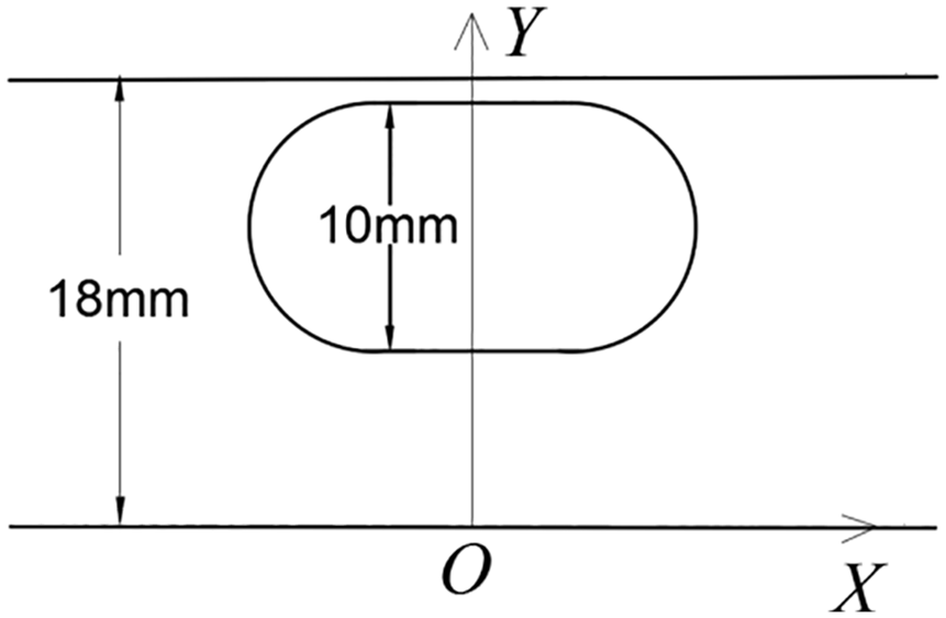
Considering the advantage of permanent magnet method, as shown in Figure 1, a capsule robot is designed, including head, tail and middle part. The head and tail are hemispherical, and a solid cylindrical magnet is built in the middle cylinder part. The upper half cylinder of the magnet is S-pole, and the lower half cylinder is N-pole. The shape of the driving external permanent magnet is annulus. The upper half annulus of the external permanent magnet is S-pole, and the lower half annulus of the external permanent magnet is N-pole. The distance between the external permanent magnet and the capsule robot is controlled, so that the capsule robot is close to the upper wall of the pipe. Initially, the external permanent magnet is located above the capsule robot (above the y-axis), and the capsule robot is in the equilibrium state. When the external permanent magnet is started to rotate around the x-axis, the capsule robot with the built-in magnet will rotate reversely around the x-axis. When the external permanent magnet moves in a straight line along the positive direction of the x-axis, the attraction force of the external permanent magnet to the capsule robot are produced. One component of the attraction force is along the positive direction of the x-axis, which drives the capsule robot to follow it along the straight line. The other component the attraction force is along the positive direction of the y-axis, which forces the right head of the capsule robot to swing up. That is to say, the capsule robot makes an irregular precession movement along the positive direction of the x-axis.
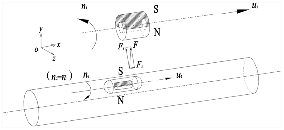
Schematic diagram of driving principle of capsule robot.
Experimental device
Composition of experimental device
As shown in Figure 2, the experimental device includes magnetic drive system, PIV test holder and PIV test system. The magnetic drive system is a three-axial motion platform, which can control the external permanent magnet to do three-axial linear and two-axial rotational motion, thus driving the magnetic capsule robot to make corresponding movement in the pipe.
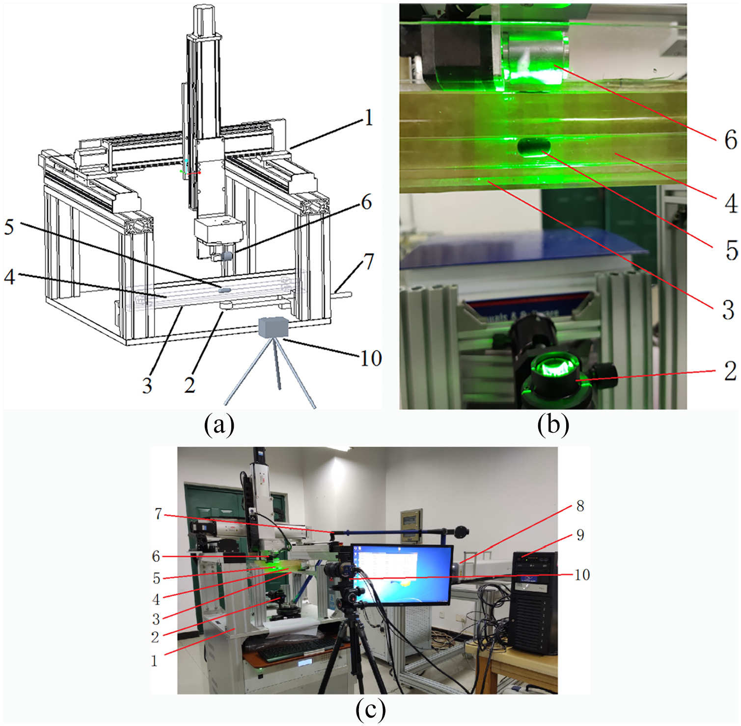
Experimental device for PIV measurement of capsule robot: (a) structure diagram, (b) local enlarged drawing, and (c) experimental device.
PIV test system
As shown in Figure 3, the PIV test holder consists of a glass tank, a glass pipe, a gasket and a pressure block. The gasket and block are respectively used for supporting and fixing the pipe. Among them, tap water is injected into the glass tank, and the two ends of the glass pipe are sealed with plugs. The pipe is filled with 201 methyl silicone oil (close to the intestinal fluid during capsule endoscopy examination) with density of 0.8 g/cm3 and viscosity of 0.1 Pa·s. The magnetic capsule robot is placed in the pipe.

PIV test holder and working principle.
The PIV test system is the particle imaging velocimetry system of LaVision company of Germany, and it mainly includes tracer particles, optical lighting system, image acquisition and processing system. Hollow glass beads provided by LaVision company are used as tracer particles with particle diameters of 8–12 μm and densities of 1.05–1.15 g/cm3. The single pulse energy of the laser is 100 mJ, the resolution of CCD (charge coupled device) camera is 2048 × 2048, and the physical size of pixel is 7.4 μm × 7.4 μm. The shooting interval of every two images is 5 ms.
The principle of PIV measurement is as follows: The CCD camera and synchronizer are controlled by computer, and laser pulse is generated by laser generator controlled by synchronizer. The piece light source lens is guided by the laser guiding arm. The piece light source lens is vertically upward and irradiates to the area to be tested in glass pipe (i.e. the operating area of the capsule robot) through water tank and water. The thickness of light source is less than 1 mm. The CCD camera lens and the piece light source lens are perpendicular to each other. The CCD camera and the laser pulse are simultaneously exposed to take particle images, and take multiple images in a short time, so as to obtain the velocity vector of particles (i.e. fluid) at different positions in the fluid field. The particle image is post processed by Davis software of LaVsion company.
When the light source directly irradiates the glass pipe surface of the capsule robot, because of the big density difference between air and glass, and the surface of the glass pipe is arc-shaped, there will be refraction phenomenon, so the sheet-shaped light irradiation surface cannot be formed in the glass pipe. The brightness of the tracer particles will also be reduced, which will affect the imaging effect and lead to the big error of the PIV measurement. In order to avoid or reduce the above refraction phenomenon, the glass pipe is put into a square glass tank, and a certain amount of water is injected into the water tank to completely submerge the glass pipe. At this time, the sheet light irradiates the bottom of the square glass tank vertically. Because of the small density difference between water and glass, the laser does not produce refraction, and the light passes through the glass pipe to form the required sheet laser area. The optical axis of CCD camera is perpendicular to the plane of light source to reduce the imaging displacement deviation of tracer particles in CCD camera.
Capsule robot prototype
As shown in Figures 4 and 5, the capsule robot with outer diameter of 10 mm and length of 18 mm has a smooth surface, its two end caps are hemispherical, and its middle part is a smooth cylinder. The capsule robot is equipped with a magnet with diameter of 6 mm and length of 5 mm. The capsule robot is made of bioplastics by 3D printing. When the sheet laser irradiates the capsule edge, in order to reduce the reflection and astigmatism and improve the collection effect of the PIV system, the capsule robot surface is black.

Capsule robot prototype.

Exploded view of capsule robot parts.
The external permanent magnet and the magnet inside the capsule are made of N38 NdFeB. The maximum magnetic energy product is 310 kJ/m3, the residual magnetic induction strength is 12.5 kGs, and the coercive force is 899 kA/m. The outer diameter of the external permanent magnet is 28 mm, the inner diameter is 12 mm, and the length is 30 mm. The distance between the external permanent magnet and the internal magnet is adjusted by the magnetic drive system to change the magnitude of the magnetic force between them. In the experiment, the distance between the central axis of the external permanent magnet and the central axis of the internal magnet is fixed at 51 mm. The glass pipes with inner diameters from 14 mm to 22 mm and length of 300 mm are used.
Numerical calculation model
Basic equations of fluid dynamics
When the capsule robot rotates and moves forward in a pipe filled with fluid, the fluid in the pipe will produce resistance and resisting moment to the capsule robot, which can be obtained by calculating the flow field of the fluid adjacent to the robot. Assuming that the fluid in the pipe is not affected by temperature and is incompressible, the fluid in the pipe satisfies the mass conservation equation and momentum conservation equation. 18

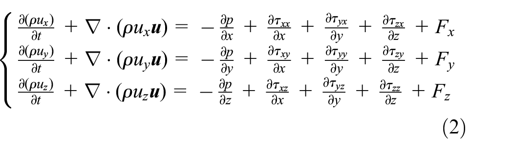
where ρ is the density of the fluid;
Equations (1) and (2) are the governing equations of fluid dynamics, which are the mathematical models for numerical calculation of fluid flow field.
It is difficult to obtain the analytical solutions of the above equations. The CFD method can be used to solve the approximate solutions which meet the practical requirements. The steps to solve the problem are as follows: using Pro/E software to establish the three-dimensional model of the capsule robot system, using Gambit software to divide the mesh and set the boundary conditions, and using CFD software to set the solution parameters and numerical solution.
Vorticity of fluid
Vorticity refers to the curl of the velocity, which is twice of the angular velocity. It reflects the rotational speed of the fluid micro clusters around their center. Vorticity is a vector, and its direction is determined by the right hand rule. When the right hand clenches the fist, the direction of four fingers is the fluid rotational direction, and then the thumb points to the direction of vorticity. 19
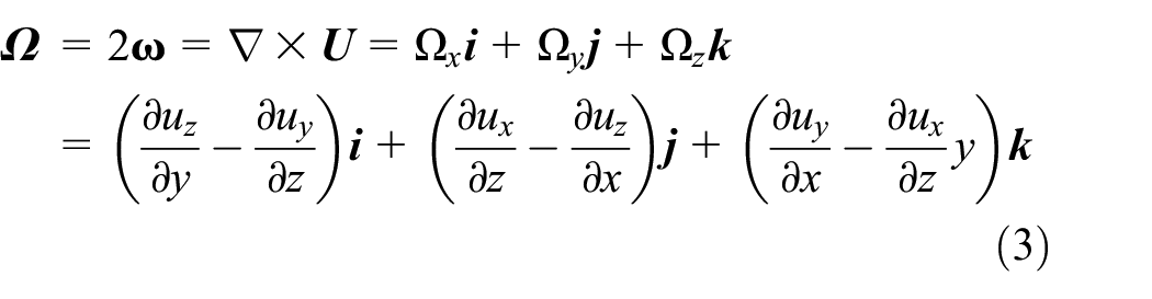
where
Numerical calculation method
3D model of capsule robot system
As shown in Figure 6, according to the above experimental conditions, the 3D model of capsule robot system is established by using Pro/E software. The system includes pipe, capsule robot and mucus. The length of the pipe is 300 mm, the two ends are closed, and the diameter of the pipe d are 14 mm, 16 mm, 18 mm, 20 mm, and 22 mm, respectively. The capsule robot has a length of 18 mm and an outer diameter of 10 mm. The mucus is the 201 methyl silicone oil. The center line of the capsule robot is parallel to the center line of the pipe. In order to simulate the rotation of the fluid around the capsule robot, a layer of wrapped fluid is designed on the surface of the capsule robot. The wrapped fluid has the same shape as the capsule, with a thickness of 0.5 mm and a distance of 0.5 mm from the upper wall of the pipe.
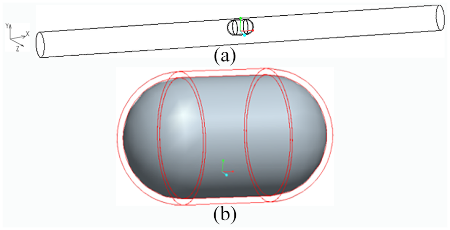
3D diagram of capsule robot system (d = 18 mm): (a) whole, and (b) wrapped fluid.
Divided gird of capsule robot system
For the fluid filled in the pipe, two fluid zones are set up, namely the capsule-shaped fluid zone around the robot and the residual fluid zone. Considering the geometry of the two fluid zones, the unstructured tetrahedral mesh is selected. At the same time, the dense mesh is used in the capsule-shaped fluid zone. The divided grid of the robot system is shown in Figure 7.
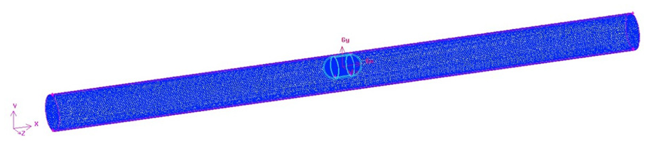
Mesh of the capsule robot system (d = 18 mm).
Model selection and parameter setting
As mentioned above, in the capsule robot system, the fluid flow in the pipe is turbulent. The turbulent model uses the standard k-ε model, and the flow near the wall is treated by the standard wall function. The density of the 201 methyl silicone oil in the pipe is 0.8 g/m3 and the dynamic viscosity is 0.1 Pa·s. According to the experimental conditions, the rotational speed of the robot is 120 r/min and the linear speed is 0.4 m/s. The gravity of the fluid is considered, and the direction is the negative direction of the y-axis. But the gravity of the robot is not considered because the robot is in equilibrium state during the experiment. The standard SIMPLE algorithm is used to solve the coupled equations of pressure and velocity. The difference schemes of pressure, momentum, turbulent kinetic energy and dissipation rate are all first-order upwind schemes. In order to simulate the motion of the fluid near the robot, the sliding mesh method is used to deal with the problem.
According to the intestinal characteristics and experimental conditions, the two ends of the pipe are set as walls, and the fluid flow is not considered. All initial conditions are set to zero. The whole numerical calculation is based on the unsteady state calculation and the dynamic mesh method. It is assumed that the robot precesses in a straight line along the positive direction of the central axis of the capsule. The convergence accuracy is: continuity, velocities in x, y, z direction, k and ε are all 0.001.
Grid independence analysis and time independence verification
When the capsule robot rotates in the pipe, the turbulent intensity of the fluid around the robot will change with the change of the rotational speed of robot, which will also affect the running state and performance of the robot. So the turbulent intensity of the fluid around the robot is taken as the index of grid independence analysis and time independence verification. 20 Figure 8 shows the variation curve of fluid turbulent intensity around the capsule robot with the change of grid number and time step when the gird quality meets the calculation requirements. The figure shows that the turbulent intensity of the fluid around the capsule robot is stable when the grid number reaches 250,000. When the grid number is 250,000 and the time step is 0.0005 s, the turbulent intensity of the fluid around the capsule robot is basically unchanged. Finally, the total grid number in the two fluid regions of the robot system is determined to be 251,764, and the time step of numerical calculation is determined to be 0.0005 s.
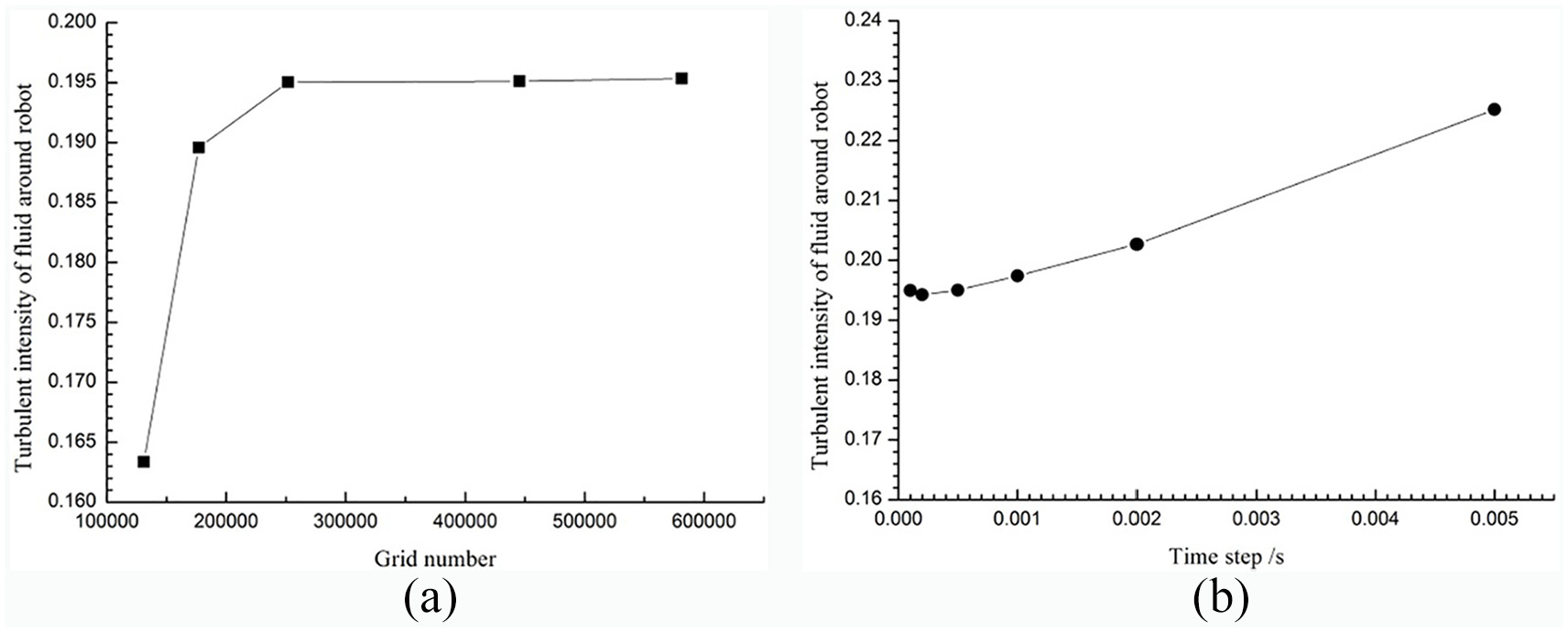
Grid independence and time independence verification diagram: (a) grid independence, and (b) time independence.
Results and analysis
When the capsule robot rotates and moves forward in a pipe filled with silicone oil, the pressure and velocity of fluid in the pipe change with time. The characteristics of fluid mainly include the fluid velocity, streamline and vorticity.
In the experiment, the translational speed of the external permanent magnet is set as 0.04 m/s and the rotational speed is 120 r/min. The capsule robot follows the external permanent magnet to make corresponding precession motion. In the simulation calculation, it is assumed that the capsule robot will move in a straight line with the same translational and rotational speed as those of the external permanent magnet.
Streamline and velocity of fluid in pipe
Considering that the picture of fluid flow field in the pipe taken by the CCD camera should be the fluid flow field of the xoy section through the center of capsule robot, the light source laser irradiates the surface of capsule robot and refracts, so the fluid flow field displayed within the contour line of capsule robot on the xoy section is actually the fluid flow field in the pipe between the capsule robot and the CCD camera. Therefore, the experimental results do not show the fluid flow field within the capsule contour.
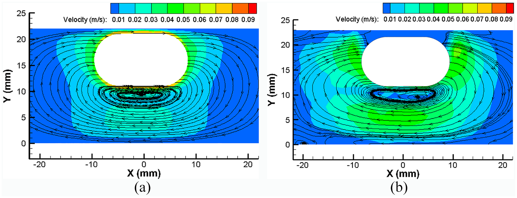
Figures 9 to 13 show the superposition of the fluid streamline and velocity nephogram of the xoy plane passing through the center of the capsule robot in the horizontal position under different pipe diameters. In these figures, (a) is the numerical calculation result and (b) is the experimental measurement result. For the convenience of comparison, the fluid velocity magnitude in different-diameter pipes is set to the same range. The diameter of the pipe shown in the longitudinal coordinate is 1 mm larger than the actual size during the experimental measurement in the figure. This is because the wall thickness of all the test pipes is 2 mm, the laser will refract when entering the arc glass from water, and the refractive index of the glass is greater than the refractive index of water, and the display size of the pipe is slightly larger than the actual size.

Superposition of fluid streamline and velocity nephogram on the xoy plane of fluid in pipe (d = 14 mm): (a) numerical calculation and (b) experimental measurement.
Superposition of fluid streamline and velocity nephogram on the xoy plane of fluid in pipe (d = 16 mm): (a) numerical calculation, and (b) experimental measurement.

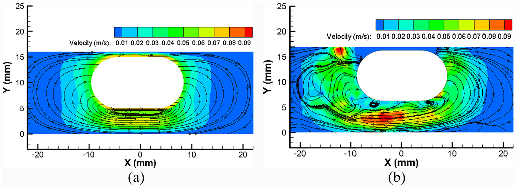
Superposition of fluid streamline and velocity nephogram on the xoy plane of fluid in pipe (d = 18 mm): (a) numerical calculation, and (b) experimental measurement.

Superposition of fluid streamline and velocity nephogram on the xoy plane of fluid in pipe (d = 20 mm): (a) numerical calculation and (b) experimental measurement.
Superposition of fluid streamline and velocity nephogram on the xoy plane of fluid in pipe (d = 22 mm): (a) numerical calculation and (b) experimental measurement.
It is found that the capsule robot runs in a wavy shape in the pipe, and the swing amplitude is mainly related to the linear speed in the experiment. Therefore, the experimental results of the horizontal state of the capsule robot are selected for analysis.
The figures show that the fluid around the capsule robot flows from the head to the tail in a circular way. The bottom of the capsule robot will form a large-scale fluid vortex. With the increase of the diameter of the test pipe, the size of the fluid vortex is increased. The maximum velocity of the fluid around the capsule robot appears below the fluid vortex. When the diameter of the test pipe is increased, the velocity of the fluid around the capsule robot is decreased, which indicates that the resistance of the capsule robot will be decreased. By comparing the numerical calculation and experimental measurement results of the streamline and velocity of the fluid around the capsule robot in the different-diameter pipes, it can be seen that the fluid streamline shape of the numerical calculation is basically similar to that of the experimental measurement. The streamline distribution in the numerical calculation is relatively uniform, while the experimental measurement is relatively disordered. This is because in the numerical calculation, we assume that the capsule robot precesses along a straight line, while the capsule robot precesses in a wavy way in the pipe during the experiment. Therefore, in the future research, we can measure the trajectory of the capsule robot. The numerical calculation needs to be piecewise, and it is assumed that the robot runs along this trajectory.
Although there is a big fluid vortex at the bottom of the capsule robot, the smaller size of the vortex is not obvious in the figures. Moreover, the intensity of the vortex is uncertain and the distribution is chaotic, so it is difficult to identify and quantify it. Therefore, it is necessary to further analyze the fluid vorticity.
Vorticity of fluid in pipe
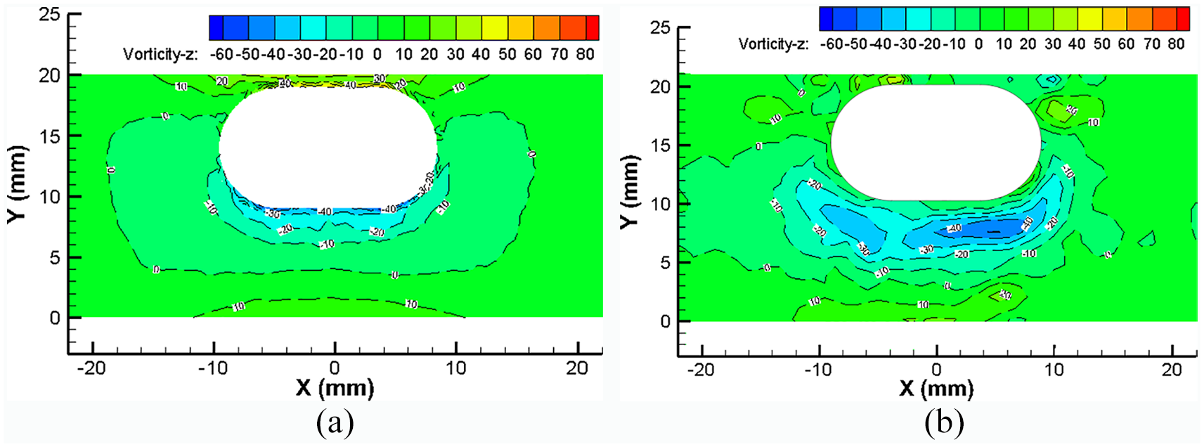
Figures 14 to 18 show the vorticity around the z-axis of the fluid of the xoy plane passing through the center of the capsule robot in the horizontal position under different pipe diameters. In these figures, (a) is the numerical calculation result and (b) is the experimental measurement result. For the convenience of comparison, the fluid vorticity magnitude in different-diameter pipes is set to the same range.

Vorticity on the xoy plane of fluid in pipe (d = 14 mm): (a) numerical calculation and (b) experimental measurement.

Fluid vorticity on the xoy plane of fluid in pipe (d = 16 mm): (a) numerical calculation and (b) experimental measurement.

Fluid vorticity on the xoy plane of fluid in pipe (d = 18 mm): (a) numerical calculation and (b) experimental measurement.
Fluid vorticity on the xoy plane of fluid in pipe (d = 20 mm): (a) numerical calculation and (b) experimental measurement.
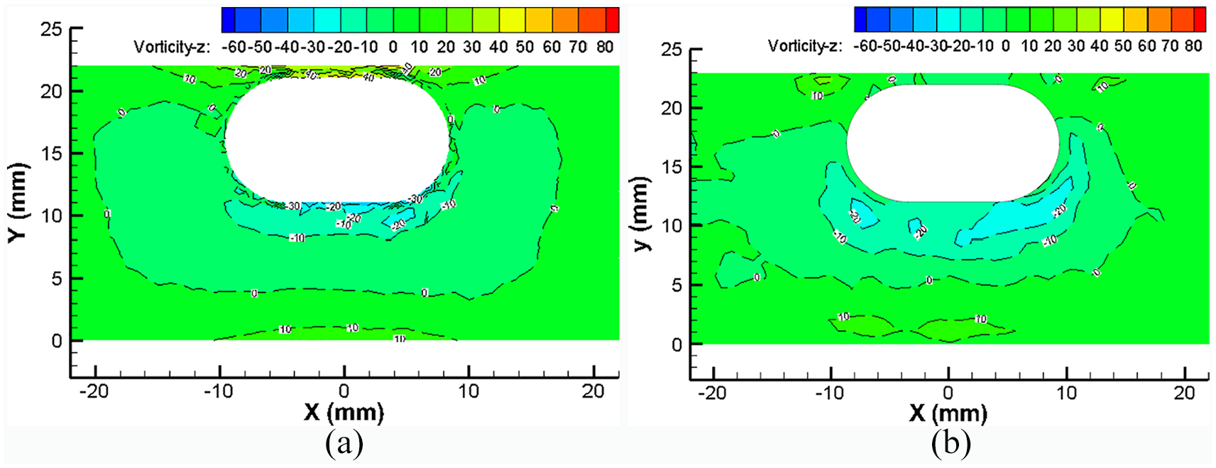
Fluid vorticity on the xoy plane of fluid in pipe (d = 22 mm): (a) numerical calculation and (b) experimental measurement.
In the vorticity diagram, the blue zone is the fluid zone that rotates clockwise around the z axis, and the vorticity is negative. The red zone is the fluid zone that rotates anticlockwise around the z axis, and the vorticity is positive. The darker the color is, the greater the vorticity value is.
The figures show that the fluid at the bottom area of the capsule robot is blue, and the value is negative, indicating that the fluid rotates clockwise around the z-axis. The fluid at the lower part of the capsule robot near the bottom of the pipe is red, and the value is positive, indicating that the fluid rotates anticlockwise around the z-axis. When the diameter of the pipe is increased, the vorticity of the fluid around the capsule is decreased, which indicates that the rotational angle speed and the rotational strength of the fluid are decreased, and the resisting moment and energy consumption of the robot will be decreased.
Compared with the results of numerical calculation and experimental measurement of the fluid vorticity around the capsule robot in different-diameter pipes, it can be seen that the distribution and size of the vorticity calculated by numerical calculation are basically similar to those of the experimental measurement. The distribution of the vorticity in the numerical calculation is relatively regular, while the distribution of the experimental measurement is relatively chaotic. This is also because the curvilinear motion of the capsule robot in the pipe affects the vorticity distribution of the surrounding fluid.
Considering the streamline, velocity and vorticity of the fluid around the capsule robot, although the numerical calculation has been simplified, the numerical calculation results are basically consistent with the experimental measurement results, which proves that the CFD calculation method used in this paper is effective and correct.
Quantitative comparison of numerical results and experimental results
In order to quantitatively compare the velocities of the fluid around the capsule robot at different positions in the pipe, as shown in Figure 19, a two-dimensional rectangular coordinate system is established. The origin of the coordinates is the bottom position of the pipe corresponding to the vertical downward of the center of the capsule, the positive direction of the x-axis is horizontal to the right, and the positive direction of y-axis is the vertical upward.
Reference coordinate system for comparison of fluid vorticity in the pipe.
Figure 20 is a comparison of numerical calculation and experimental measurement results of fluid vorticity around z-axis in the coordinate system shown in Figure 19. The figures show that from the bottom of the pipe to the bottom of the capsule robot, the vorticity of the fluid around the z-axis is gradually decreased from positive to negative. The numerical results by the CFD method are in good agreement with the experimental results by the PIV technology, which further proves that the CFD method used in this paper is reasonable and correct.

Comparison of numerical calculation and experimental measurement of fluid vorticity around z-axis at the lower zone of capsule robot (d = 18 mm, v = 0.04 m/s, n = 120 r/min).
Force calculation of capsule robot
The PIV technology can only measure the instantaneous flow field of the fluid in the pipe when the capsule robot is running. At present, it is difficult to measure the force of the capsule robot when it running in the pipe, and there is no related literatures. Therefore, we use the above CFD method to numerically calculate the resistance and resisting moment of the capsule robot.
Figure 21 shows the resistance in x-axial (forward) direction and resisting moment around x-axial direction of capsule robot with the increase of pipe diameters from 14 mm to 22 mm when the capsule robot runs to horizontal position. The figure show that when the capsule robot precesses at a linear speed of 0.04 m/s and a rotational speed of 120 r/min, with the increase of the pipe diameters, the resistance in the forward direction and the resisting moment around the forward direction of the capsule robot are all decreased, that is to say, the energy consumption of the capsule robot is reduced and the operating state is more stable.

Force of the capsule robot during precession (x-axial direction).
Conclusion and future work
The experimental measurement device for the fluid flow field in the pipe of the capsule robot driven by permanent magnet method is designed and manufactured. Using the PIV technology, the fluid flow field (the fluid streamline, velocity and vorticity) in the pipe is measured when the magnetic-controlled cylindrical capsule robot is running in the pipe filled with silicone oil. The magnetic capsule robot makes a corresponding precession motion under the drive of an external permanent magnet, and the motion trajectory is wavy. The swing amplitude of the capsule robot is mainly related to its linear speed.
The CFD method is used to numerically calculate the force of the capsule robot. The sliding mesh method and the dynamic mesh method are used to simulate the precession motion of the capsule robot. When the pipe diameters are increased, the resistance in the forward direction and the resisting moment around the forward direction of the capsule robot are all decreased, that is to say, the energy consumption of the capsule robot is reduced and the operating state is more stable
The streamline, velocity and vorticity of the fluid in the pipe of the capsule robot are studied experimentally and numerically. The results show that the fluid around the capsule robot flows from the head to the tail in a circular way. The bottom of the capsule robot will form a large-scale fluid vortex. With the increase of the diameter of the test pipe, the size of the fluid vortex is increased. When the diameter of the test pipe is increased, the velocity and vorticity of the fluid around the capsule robot is decreased, which indicates that the resistance, resisting moment and energy consumption of the capsule robot are all decreased. The streamline distribution in the numerical calculation is relatively uniform, while the experimental measurement is relatively disordered. The distribution of the vorticity in the numerical calculation is relatively regular, while the distribution of the experimental measurement is relatively chaotic. The difference between the numerical calculation results and the experimental measurement results is mainly due to the assumption that the capsule robot precesses along a straight line in the numerical calculation and the capsule robot precesses in a wavy way in the pipe during the experiment. The quantitative comparison of fluid vorticity at lower zone of the capsule shows that the numerical results by the CFD method are in good agreement with the experimental results by the PIV technology, which further proves that the CFD method used in this paper is reasonable and correct.
The CFD method and PIV technology used in this paper can be used to calculate and measure the fluid flow field and mechanics of small size capsule robot in liquid environment.
The influences of fluid viscosity, linear speed and rotational speed of the capsule robot on its performance will be studied in the future.
Footnotes
Handling Editor: James Baldwin
Declaration of conflicting interests
The author(s) declared no potential conflicts of interest with respect to the research, authorship, and/or publication of this article.
Funding
The author(s) disclosed receipt of the following financial support for the research, authorship, and/or publication of this article: This work was supported in part by the National Natural Science Foundation of China under grant 51875051, the Natural Science Foundation of Hunan Province under grant 2019JJ40324, and the Scientific Research Fund of the Hunan Provincial Education Department under grants 19A047 and 18B408.
Supplemental material
Supplemental material for this article is available online.
References
Supplementary Material
Please find the following supplemental material available below.
For Open Access articles published under a Creative Commons License, all supplemental material carries the same license as the article it is associated with.
For non-Open Access articles published, all supplemental material carries a non-exclusive license, and permission requests for re-use of supplemental material or any part of supplemental material shall be sent directly to the copyright owner as specified in the copyright notice associated with the article.