
Abstract
Two damping rings (DRs) are added on a nonlinear free-free elastic beam to reduce vibrations. This elastic beam with free-free boundary conditions can be used to simulate the high speed aircraft fuselage vibrations. Both isotropic beam and compound beam with double-section are investigated. The beam is subjected to a distributed load with the harmonic wind force. The method of multiple scales ((MOMS) a perturbation technique) is employed to analyze this nonlinear problem in frequency domain. DRs with various locations, masses, spring constants, and damping coefficients are analyzed and the maximum amplitude counter plots (MACPs) are compiled to identify DRs’ combinations for the optimal damping effects. The Floquet theory is used to make the basin of attraction (BOA) charts and analyze the stability of the system. This research can be applied in a wide range of engineering problems, such as rocket structures, high-speed aircrafts, satellites, missiles, etc.
Introduction
Studies of vibrations have always been a concern for researchers and engineers because it may cause the structural fatigue or failure. Beams are widely applied in engineering problems, such as wings in aerospace engineering, bridges in civil engineering, and train rails in mechanical engineering, etc. Many studies on beam vibrations have been performed. Özkaya 1 considered a beam-mass system under simply supported end conditions. The effects of positions, magnitudes, and the number of the masses were investigated. Mundrey 2 considered the 2D Euler-Bernoulli beam resting on an elastic foundation to simulate the railway track. A moving load on the 2D beam was studied. Chang 3 studied nonlinear vibrations in carbon nanobeams under magnetic field. The analytical study was performed by using He’s variational method. Wang and Wei 4 used a fluid-conveying nonlinear beam and nonlinear springs to simulate the vibration of a fluid-conveying tube placed on an elastic foundation. The internal resonance was found under a certain combination of fundation elastic modulus and flow speed. In most nonlinear beam problems, the internal resonance is a major point of discussion. Due to nonlinearity, internal resonance generally occurs in modes that are not being directly excited by external forces. Exciting higher modes can lead to high amplitude vibrations in lower modes. 5 What is interesting is that in common 3D beams with symmetrical cross sections; one-to-one internal resonance is the most likely to take place among the various degrees of freedom. As its resonant frequency is the same with each other, it is also called primary resonance. Pai 6 analyzed the primary resonance in a 3D nonlinear composite rotating beam. Stoykov and Ribeiro 7 examined the stability of a 3D nonlinear rotating beam based on Timoshenko’s theory and took into account the deformation caused by twists and warps. They used Floquet theory to analyze the stability of the system and determined that the primary resonance produces supercritical symmetry-breaking bifurcation in beams with a square cross-section. Chang and Wang 8 studied the primary resonance in a 3D nonlinear free-free beam. Tekin et al. 9 considered the three-to-one internal resonance in 2D multiple stepped beam systems with clamped-clamped, pinned-pinned, and clamped-pinned supports. Wang and Chang 10 analyzed the primary and internal resonance in 3D free-free double-section beam.
The way to effectively suppress vibrations is always a problem to engineers. Wang and Kuo 11 examined the vibrations in a nonlinear hinged-free beam resting on a nonlinear elastic foundation. They discovered that with a certain spring constant in the elastic foundation, three-to-one internal resonance occurs in the first and second modes of the system. They prevented internal resonance and reduced vibrations by adding a tuned mass damper (TMD) on the beam. Their results revealed that the best damping effects could be obtained when the tuned mass damper was placed between 0.25l and 0.5l from the fixed end of the beam. Wang and Liang 12 studied the damping effects of a lumped-mass vibration absorber on a hinged-hinged nonlinear beam resting on a nonlinear elastic foundation. Using the maximum amplitude contour plots (MACPs), they obtained the optimal mass and spring constant combination of the lumped-mass vibration absorber for the best vibration reduction. Wang et al. 13 also found that when the multiple value of mass and spring constant (mDk) of the tuned mass damper equals to a certain value (mDk = 0.0475), the best vibration reduction effect can be obtained. Wang and Hsiao 14 studied the off-shore wind turbine tower by using the 3D nonlinear multi-loaded slender beam to simulate the vibration of the turbine tower. They added two damping rings (DRs) to prevent internal resonance and suppress vibration. They concluded that adding one of the damping rings on the top of the turbine tower and the other one on the ocean surface of the tower will produce better damping effects. These studies demonstrate that changing the location, mass, spring constant, and damping coefficient of the tuned mass damper are feasible approaches to prevent internal resonance and mitigate vibrations.
This study considers a nonlinear free-free beam subjected to a distributed load with the harmonic wind force. The isotropic beam and compound beam with double-section are investigated. Two damping rings are added on the beam. Damping rings with various locations, masses, spring constants, and damping coefficients are analyzed and the maximum amplitude counter plots are compiled to identify damping rings’ combinations for the optimal damping effects. This study also uses Floquet theory to analyze the stability of this flow-structure coupled system. The results are verified by numerical method (the 4th order Runge-Kutta method) and ANSYS simulations.
Theoretical model
Isotropic free-free beam model
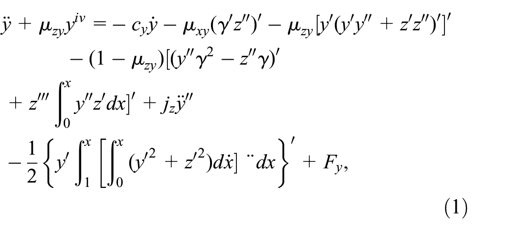
This study analyzes the vibrations on a straight 3D free-free nonlinear beam, which can be simulated to high speed aircrafts such as rocket, missiles, etc. The coordinate definitions of the beam and the relationships between various external forces and damping rings are presented in Figure 1. Three consecutive Euler angles are used to relate the deformed and undeformed states. The equations contain structural coupling terms and quadratic and cubic nonlinearities due to curvature and inertia. Based on Newton’s second law, Euler’s angle transformation, and Taylor series expansion, the dimensionless equations of motion of the nonlinear beam can be expressed as follows11,12,15 (please see Appendix A for details):

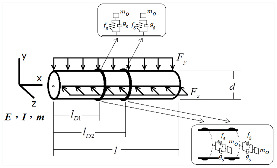
Schematic model of an isotropic free-free beam with multiple forces and damping rings.
where y and z are beam displacements in the y- and z-directions, respectively. Those terms with a “.” on the upper or upper right denotes d/dt, and with a “′” denotes d/dx. In which cy,z represent the dimensionless structural damping coefficient in the y- and z-directions, respectively. The mass moments of inertia are denoted as jy,z in the y- and z-directions, respectively. They are non-dimensionalized by beam mass (m) and length (l). Fy,z are the dimensionless forces in the y- and z-directions, respectively. The dimensionless flexural rigidities of the elastic beam are defoined as
Assuming the beam is subjected to a distributed load with the harmonic wind force

In which qy,z and


where
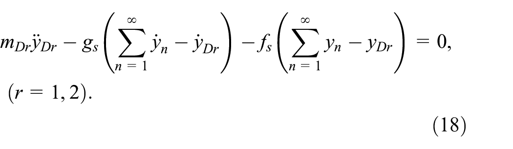
Damping rings can be considered as external forces produced by two tuned mass dampers in the y- and z-directions of the beam. The influence of damping rings will be discussed detaily in later sections. The equation of motion of the damping ring is derived by using Newton’s second law as follow:

The index r = 1,2 represents two damping rings. Replacing

The concept of the damping ring is originally designed to reduce the vibration of space rocket in this work. One can use the rubber, silicone or any other suitable materials to make the damping ring. The material properties (
Using Newton’s second law, the integrated dimensionless equations of motion of the nonlinear beam can thus be written as


where lDr (r = 1,2) indicates the location of the first and second damping ring on the beam, and
The dimensionless boundary conditions of the beam are


Double-section free-free beam model
This section considers the compound structural problem. The schematic of the double-section free-free beam is shown in Figure 2. Two damping rings are added on the double-section beam. Similarly, the equation of motion of damping rings can be obtained by using Newton’s second law. The dimensionless equations of motion of this double-section beam can be written as:


Schematic of a double-section free-free beam with damping rings.
The boundary conditions and the compatibility equations on the joint of two beam sections are


where
Systematic analysis of damping rings
The results from Wang and Chang 10 indicated that when y-direction is excited and with no dampers, the primary resonance would occur in the y- and z-directions. The three-to-one internal resonance will occur in the beam’s 1st and 2nd modes. Therefore, two damping rings are equipped on the beam in order to prevent internal resonance and reduce the vibrations. This study encompasses the frequency responses of the beam system with damping rings in the 1st and the 2nd modes. The fixed points plots facilitate the analysis of the influence of damping rings on internal resonance in the system.
Theoretical model of damping rings
The equation of motion of two damping rings in they-direction is
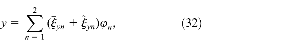
By using the separation of variables and letting

substituting the generalized coordinate

Where cc represents complex conjugate. Hence, the solution of equation (20) is

Substituting equation (21) into equation (20), the


Adding equations (21) into equation (12), one can get the beam equation with damping rings afterwards. The method to obtain the solution in the z-direction is the same with the y-direction. Furthermore, the solution for the double-section beam in time domain is conformity with the isotropic beam. The analyzed process will not repeated here.
Method of multiple scales and frequency response
This study uses the method of multiple scales to analyze the steady state frequency response (fixed points) of this coupled nonlinear system. The time scale is divided into fast and slow time scales. Supposing that


where
The frequency response of the system, for example the case of isotropic beam, can be obtained by substituting equation (21) into equations (12) and (13) of order

where
The secular terms must be selected to obtain the solvability conditions. Regarding the y-direction’s first mode, for example, the harmonic secular terms include the terms of


Next, take the square of equations (27) and (28) and sum them together to eliminate the terms associated with time in

Once the wind speed

Fixed points plots of the double-section beam with diameter ratio = 1/0.75, no DR added: (a)

Fixed points plots of the double-section beam with diameter ratio = 1/0.75, with DR (mDr = 0.01, lD1 = 0.0001, lD2 = 0.9999, fs = 1.0, gs = 0.1): (a)
Floquet theory and stability analysis
This section discusses the effects of damping rings on system stability. In equations (8), (9), (12), and (13), the magnitude of wind speed is changed and the Floquet theory is used to analyze the stability of the system. In order to analyze the stability of the system, the perturbation technique is employed. Assuming that
where


The dynamic equation of the damping ring is

The Floquet transition matrix can be obtained by setting the state variables for one period. The differential equation with perodic coefficient (e.g. equations (33) and (34)) is expressed in state variable form as

where


where T is the period of the system. The stability criteria are defined by the Floquet multipliers (F.M.) and
Results and discussion
Damping effect analysis of damping rings
This section will analyze the vibration reduction effects of damping rings for different mass (mDr), location (lDr), spring constant (fs), and damping coefficient (gs). The 3D maximum amplitude plots (3D MAPs) and maximum amplitude contour plots (MACPs) are made to determine the optimal parameter combinations of damping rings.
For the case of isotropic beam, by solving the solvability conditions (equations (29)–(31)), the fixed points plots are made for different parameter combinations: mDr = 0.02∼0.1, lD1 = 0.0001∼0.8, lD2 = 0.9999, fs = 1.0, 5.0 and 9.0, gs = 0.1, 0.5 and 0.9. The maximum amplitudes for each case are chosen to make the 3D maximum amplitude plots (3D MAPs). Figure 5(a)–(c) show the isotropic beam’s 1st mode maximum amplitudes in y-direction when the 1st mode was excited. Figure 5(a)–(c) are the 3D MAPs for the cases of damping ring’s damping coefficient gs = 0.1, 0.5 and 0.9, respectively. This study fixes the 2nd DR near the beam end (lD2 = 0.9999) and changes the 1st DR’s positions (lD1 = 0.0001∼0.8). In Figure 5, the x-axis is the mass of the damping ring, the y-axis is the position of the damping ring, and the z-axis is the maximum amplitude corresponding to the combinations of the mass and the position of the damping rings. The different amplitude intervals are divided by different colors: red indicates higher amplitude interval, while blue indicates lower amplitude interval, which represents the better vibration reduction effect. These figures show that the minimum amplitude occurs when fs = 9.0, and the damping rings are placed at 0.0001 and 0.9999.

3D MAPs of the isotropic beam y-direction’s 1st mode, when the 1st mode was excited: (a) gs = 0.1, (b) gs = 0.5, and (c) gs = 0.9.
Although the 3D MAPs can provide the general design concept of damping rings, it is difficult to see the optimal combination of damping rings due to numerous damping rings’ parameters. Therefore, this study makes the MACPs and analyzes the influence of damping rings’ positions and masses on the system. According to the results of the 3D MAPs, fs = 9.0 has the best damping effect. Different gs case of MACPs are made to examine the gs effects. Figure 6(a)–(c) show that when damping rings are located on 0.0001 and 0.9999, the system has the best vibration reduction effect. The reason is that the maximum amplitudes of the first mode of the elastic beam are located on 0 and 1 (both ends of the beam), respectively. The optimal vibration reduction effect can be achieved by placing damping rings on the maximum amplitude of each mode. It is noteworthy that the larger the gs might not have the better effect of vibration reduction. The best damping effect occurs when gs = 0.5. By comprehensive analyzing the 3D MAPs and MACPs, this study concludes that the optimal damping rings vibration reduction combination for the y-direction’s first mode is mDr = 0.04, lD1 = 0.0001, lD2 = 0.9999, fs = 9.0, gs = 0.5.

MACPs of the isotropic beam in y-direction’s 1st mode, when the 1st mode was excited, fs = 9.0: (a) gs = 0.1, (b) gs = 0.5, and (c) gs = 0.9.
Next, damping effects of the double-section beam are analyzed. Figsure 7(a) and (b) are the MACPs for the double-section beam with

MACPs of the double-section beam with diameter ratio 1/0.75,
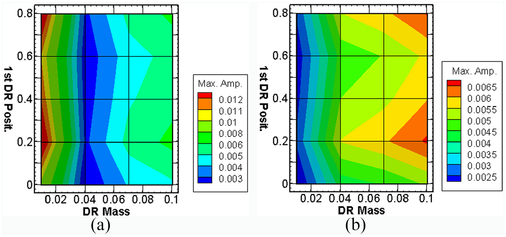
MACPs of the double-section beam with diameter ratio 1/0.75,
Table 1 shows the results of the vibration reduction effects with damping rings. In which Amp. (no DRs) is the maximum amplitude of each mode without damping rings, 10 and Amp. (with DRs) is the maximum amplitude of each mode with damping rings. The “Effect” is expressed as a percentage of the vibration reduction effects for each mode under different cases. Table 1 shows that vibration reduction effect is remarkable when the DRs are added. In addition, the vibration reduction effect of the DRs on the first mode is greater than that on the second mode.
Damping effects of damping rings.

DRs combination: mDr = 0.04, lD1 = 0.0001, lD2 = 0.9999, fs = 9.0, gs = 0.5.
DRs combination: mDr = 0.04, lD1 = 0.0001, lD2 = 0.9999, fs = 9.0, gs = 0.9.
DRs combination: mDr = 0.01, lD1 = 0.0001, lD2 = 0.9999, fs = 9.0, gs = 0.5.
DRs combination: mDr = 0.01, lD1 = 0.0001, lD2 = 0.9999, fs = 9.0, gs = 0.9.
To further verify the correctness of the MACPs, the fourth-order Runge-Kutta (RK-4) method is used to solve the perturbation equations in time domain (equations (33)–(35)). Figure 9 is an example of the y-direction’s 1st mode MACP of the double-section beam with diameter ratio 1/0.75,

MACP of the double-section beam with diameter ratio 1/0.75,
ANSYS simulation
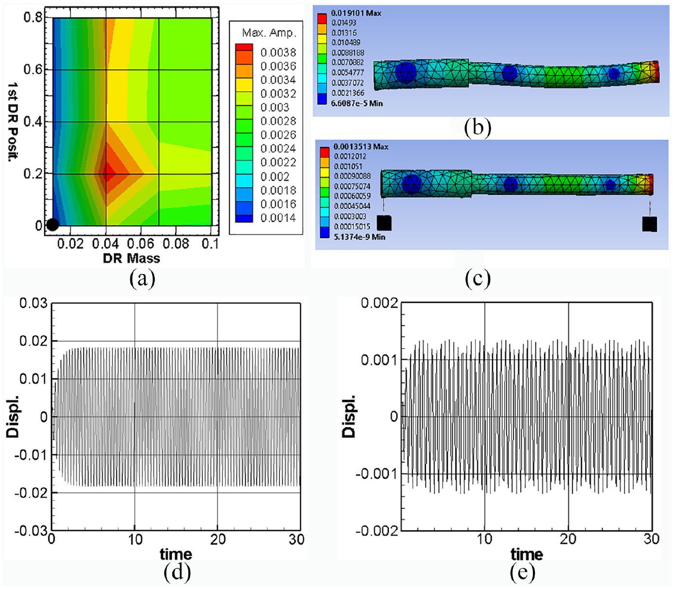
Several cases are studied by the ANSYS to further verify the results of the damping rings’ damping effect from MACPs. It is noted that the beam length is assumed to be 1 and the output amplitudes of the ANSYS are assured to be the same as the dimensionless values. The beam model was created by Solidworks commercial software. The material was set as “structural steel” and imported into ANSYS. The boundary conditions were set as free on both ends of the beam. More than 20,000 nodes and 12,000 elements were chosen. The simple harmonic function with constant amplitude was set as normal force and applied on the beam surface. Figure 10 shows the ANSYS simulation of the isotropic beam y-direction’s 1st mode amplitude, when the 1st mode was excited. Instead of gs = 0.5, we choose the DR’s parameters as gs = 0.9, fs = 9.0, mDr = 0.04, and lD1 = 0.0001 to verify different cases. Figure 10(a) is the MACP. The black dot down the figure represents the case of mDr = 0.04 and lD1 = 0.0001. The minimum amplitude shown on the MACP is 0.003. Figure 10(b) is the ANSYS simulation with no DRs. The maximum amplitude is 0.0485, which agrees with the result from Table 1 (0.051088). Figure 10(c) is the ANSYS simulation with the DRs. The maximum amplitude is 0.00288, which agrees with the result from MACP. Figure 10(d) is the numerical result with no DRs by using RK-4 method. The maximum amplitude approaches to 0.051, which agrees with the results from Table 1 and ANSYS. Figure 10(e) is the result with DRs by using RK-4 method. The maximum amplitude approaches to 0.0029, which agrees with the results from MACP and ANSYS. Figure 11 shows the ANSYS simulation of the double-section beam y-direction’s 1st mode amplitude with diameter ratio 1/0.75,

ANSYS simulation of the isotropic beam amplitudes, y-direction’s 1st mode, when the 1st mode was excited: (a) MACP, (b) ANSYS simulation with no DRs, (c) ANSYS simulation with DRs fs = 9.0, gs = 0.9, mDr = 0.04, lD1 = 0.0001, (d) RK-4 method with no DRs, and (e) RK-4 method with DRs same as (c).

ANSYS simulation of the double-section beam amplitudes with diameter ratio 1/0.75,
ANSYS simulation of the double-section beam amplitudes with diameter ratio 1/0.75,
Analysis of system stability
The stability criteria of Floquet theory is used to verify system stability for different wind speeds. By applying Floquet multipliers, if the system is stable, it is marked with a black dot, and if the system is unstable, it is not marked at all. This study analyzes the stability of the system with the value of wind speed varies from Mach number (M) = 0.54∼1.71 (the corresponding

Basin of attraction of the case of the isotropic beam (no DRs): (a) M = 0.54–1.71 Basin of Attraction, (b) M = 1.33 Basin of Attraction, (c) poincaré map of initial condition (−0.2, 0.6), (stable), and (d) poincaré map of initial condition (–0.2, 0.2), (unstable).

Basin of attraction of the case of the isotropic beam (with DRs): (a) M = 0.54–1.71 Basin of Attraction, (b) M = 1.33 Basin of Attraction, (c) poincaré map of initial condition (0.2, 0.4), (stable), and (d) poincaré map of initial condition (0.2, –0.2), (unstable).
In the double-section beam analysis, the case of

Basin of attraction of the case of the double-section beam (no DRs): (a) M = 0.48–1.53 Basin of Attraction, (b) M = 1.12 Basin of Attraction, (c) poincaré map of initial condition (−0.4, 0.6), (stable), and (d) poincaré map of initial condition (−0.4, 0.1), (unstable).

Basin of attraction of the case of the double-section beam (with DRs): (a) M = 0.48–1.53 Basin of Attraction,(b) M = 1.12 Basin of Attraction, (c) poincaré map of initial condition (0.2, 0.6), (stable), and (d) poincaré map of initial condition (0.2, 0.2), (unstable).
Conclusion
In this study, a nonlinear free-free beam is used as the main model to simulate the vibration of a rocket structure. The harmonic wind force is considered. The method of multiple scales and fixed points plots are used to analyze and verify the theory in this study. Two damping rings are equipped on the elastic beam to prevent internal resonance and reduce vibrations. The maximum amplitude contour plots (MACPs) and time response plots are created to analyze the influence of damping rings’ parameters (mass, position, spring constant, and damping coefficient) on the beam system and identify the optimal damping effect. The Floquet theory, basin of attraction, and Poincaré maps are also used to determine the stability of the system at different wind speeds. Finally, the following conclusions are proposed for this study.
The optimal placement of the damping ring depends on the maximum amplitude of each mode shape. Placing damping rings near the both ends of the beam will result in best damping effects.
Two damping rings can effectively prevent internal resonance and reduce vibration. For the isotropic beam, the optimal combination of vibration reduction parameters is mDr = 0.04, lD1 = 0.0001, lD2 = 0.9999, fs = 9.0, gs = 0.5. For the double-section beam, the optimal parameters combination is mDr = 0.01, lD1 = 0.0001, lD2 = 0.9999, fs = 9.0, gs = 0.5 and 0.9.
The basin of attraction, using Floquet theory, could predict the system divergence in cases with different wind speeds. In addition, the stability regions increase significantly after damping rings are added. The damping rings play an important role in beam vibration reduction.
Footnotes
Appendix A
Handling Editor: James Baldwin
Declaration of conflicting interests
The author(s) declared no potential conflicts of interest with respect to the research, authorship, and/or publication of this article.
Funding
The author(s) disclosed receipt of the following financial support for the research, authorship, and/or publication of this article: This research was supported by the Ministry of Science and Technology of Taiwan, Republic of China (grant number: MOST 109-2224-E-006-004).