
Abstract
Waterjet is a device that cuts or crushes materials using water pressure injected through the nozzle. Especially, Low pressure waterjet is used in stripping and cleaning work. The cleaning patterns of the low pressure waterjet is determined by various design variables, such as the number of nozzles, an angle of nozzles, gear ratio and so on. In order to optimize the cleaning pattern, the optimum waterjet design is required depending on the shape of the target structure. To do this, a large number of waterjet analysis models should be used. This study reduced design time by automating the creation of the desired analysis model with simple changes in design variables, and conducted evaluation of the cleaning patterns using numerical method for the most frequently used cylindrical structures. In addition, it analyzed the effects of changes in design variables and suggested improvements. Moreover, the idea of a module type waterjet was proposed to reduce the cost of waterjet replacement due to usage changes. This study can be used to design the waterjet, which suits a particular purpose.
Introduction
Recently, the need for environmentally friendly regulations and energy saving has been increasing in developed countries, and eco-friendly equipment that pursues low noise, low vibration, and high efficiency is attracting attention. 1 Figure 1 shows a waterjet with a high utilization efficiency in a limited space among eco-friendly demolition equipment, which is a device for crushing a structure using the water pressure. 2 It is classified as low pressure, medium pressure and high pressure waterjet depending on the pressure. Among them, low pressure waterjet is used for cleaning and stripping, medium pressure waterjet is used for industrial material and parts cutting, and high pressure waterjet is used as demolition equipment for extreme environment. 3 The waterjet is widely used throughout the industry for its use, and many researchers are studying the waterjet. Regarding the low pressure waterjet, Guha et al. 4 studied a low pressure cleaning waterjet system through a test and numerical method. In relation to the medium pressure waterjet, Hashish et al. 5 studied cutting of the waterjet using the abrasive, and Kwak 6 and Choi and Yang 7 conducted the research on the abrasive waterjet for the rock. Also, in relation to the high pressure waterjet used in the extreme environment, the research related to the ground excavation equipment in the submarine environment was carried out by Kim et al. 8 The waterjet operates on the principle that the fluid injected through the nozzle attacks the structure. Thus, the design for the nozzle system, such as the variables for the nozzle and the type of fluid to be injected, plays an important role in the work performance. Jung et al. and Choi et al.9,10 conducted an optimal design for the nozzle system of the cleaning waterjet used in the car wash equipment and Jeon et al. 11 studied the efficiency according to some condition when cleaning the contaminants of the wind turbine blade using the water jet. Oh et al.12,13 analyzed the influence of the abrasive and the variable of a combined nozzle. However, these studies focus on the design of the waterjet itself.

Various type of waterjet models. 2
In the work of cutting and crushing some structure or cleaning of a storage tank using waterjet, the attack trajectory(a set of waterjet crushing points) generated by the behavior of the waterjet nozzle is highly related to the work efficiency. These trajectories are called a fracture pattern or a cleaning pattern. By optimizing the cleaning pattern that occurs during the waterjet driving, it is possible to save the working time and the working cost. Therefore, the cleaning pattern needs to be studied.
This study focused on the low pressure waterjet, which is widely used for cleaning and detaching the inside of a storage tank. The cleaning pattern of the low pressure waterjet is determined by various design variables, such as the number of nozzle bodies, the number of nozzles, the angle of the nozzle, and the gear ratio. In addition, it is necessary to create a large number of analysis models since the optimal cleaning pattern varies depending on the shape of the target structure. In this study, by developing the pattern design automation program that can cope with the change of the structure, the designer can create the waterjet analysis model with the desired shape and pattern. Also, it is possible to visualize and analyze the attack points and pattern of the waterjet on structures with various target shapes. Even if the target structure is changed, the design can be easily applied.
Figure 2 shows the various type of low pressure waterjet models being sold. These are commonly used in sewer pipes and storage tanks, so they are usually installed inside a cylindrical structure. In this study, the cleaning pattern was evaluated and analyzed for the cylindrical structure using the developed program. The waterjet cleaning pattern was evaluated by visualizing the attack points obtained from the developed analysis model and pattern design automation program. And, a numerical analysis technique has been developed to determine the work efficiency for cylindrical structures. The area that was attacked for a certain period of time was derived and selected as the evaluation criterion for work efficiency. Through the selected evaluation criteria, work efficiency was analyzed according to the change of design variables. Based on the results of the analysis, the idea of making improved waterjet was presented.

Waterjet target structure with cylindrical type.
Waterjet analysis model
Driving mechanism for waterjet models
To generate the analysis model for the waterjet, an analysis on the waterjet driving mechanism is needed. Figure 3 shows a schematic model of the low pressure waterjet model. It can be divided into three parts: input part, stem part, nozzle body part. An impeller rotates when water pressure is applied to the top of the input part through the water pump. With these rotation, a planetary reduction gear located in the stem part generates torque to obtain the driving force, and the torque is transmitted along the axis from the stem part to the nozzle body part. When the entire nozzle body part is rotated, the nozzle body part connected by a bevel gear also rotates. Finally, the water from the top of the input part is sprayed out through the nozzles, and the water attacks the target structure, resulting in the waterjet cleaning pattern. The water is used to rotate the nozzle body part and to attack the target structure. Therefore, it has a driving mechanism using pure fluid which does not require any other power such as a motor.
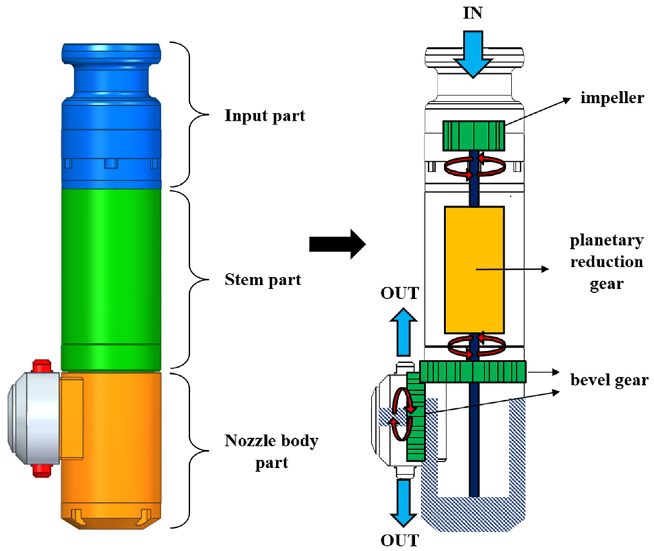
Schematic model of the waterjet analysis model.
The following is a detailed description of the three parts that make up the waterjet.
Input part
The input part is where the flow enters the waterjet. As described above, it is the part that serves as a power input. The impeller acts as a rotor, and it is rotated rapidly by the hydraulic pressure of the pump. Using the pump, the number of rotations entering the input can be determined.
Stem part
The fluid used to rotate the impeller flows out to the nozzle body part through the stem part. An important component of the stem part is a planetary reduction gear. It plays a role of converting the rapid rotation to high torque, is shown in Figure 4. It is composed of internal gear, planet gear and sun gear. The detailed mechanism of the planetary reduction gear used in the low pressure waterjet is shown in Figure 5. The gearbox itself is a ring gear having 44 teeth. The torque is transmitted to three planetary gears having 14 teeth through the input gear with 16 teeth, and it transmitted to the next planetary gear through a sun gear with 10 teeth. In the next step, it consists of three planetary gear sets with 17 and 10 teeth. Based on the gear teeth shown in Figure 5, the gear ratio for input and output was calculated by equation (1).
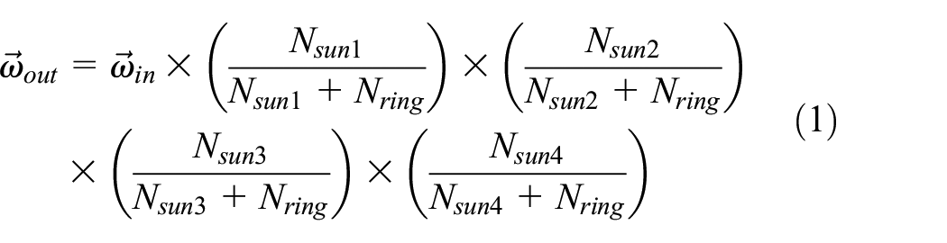
As a result, it can be seen that the planetary gear of the waterjet has 1/590 reduction ratio, and it was used in the design.

Planetary gear for waterjet system.

Number of teeth ratio of planetary reduction gear.
Nozzle body part
The nozzle body part is the part where the nozzles are attached, and the increased torque through the planetary gear rotates the entire nozzle body part. As shown on Figure 6, the nozzle body part is divided into two parts, the nozzle main body and the nozzle body. The rotating part of the nozzle main body is called tee housing. The shape of this part changes according to the angle and the number of the nozzle body. The lower part of the stem part located at the center of the tee housing is fixed, and the whole tee housing is rotated by the bevel gear fixed to the stem part. The entire tee housing rotates by the shaft connecting the planetary gear and the bottom of the tee housing. In addition, the entire nozzle body is also rotated by the driving bevel gear (nozzle) and fixed bevel gear (stem). Therefore, the kinematic relationship between nozzle main body and nozzle body rotation depending on the bevel gear ratio affects the final cleaning pattern. By using this, it is possible to evaluate the waterjet cleaning pattern by changing the design parameters such as the number of teeth of the bevel gear and the shape of the nozzle part.

Schematic model of nozzle body part.
Automation program of the waterjet modeling
Design variables
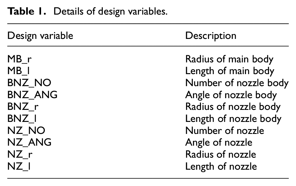
Based on the mechanism of the waterjet which is analyzed above, the selected design variables are shown in Figure 7 and Table 1. Cleaning pattern design automation program was developed using these design variables. For the efficiency of the automated design, the body of the water jets was simplified into three parts: main body, nozzle body, and nozzle.
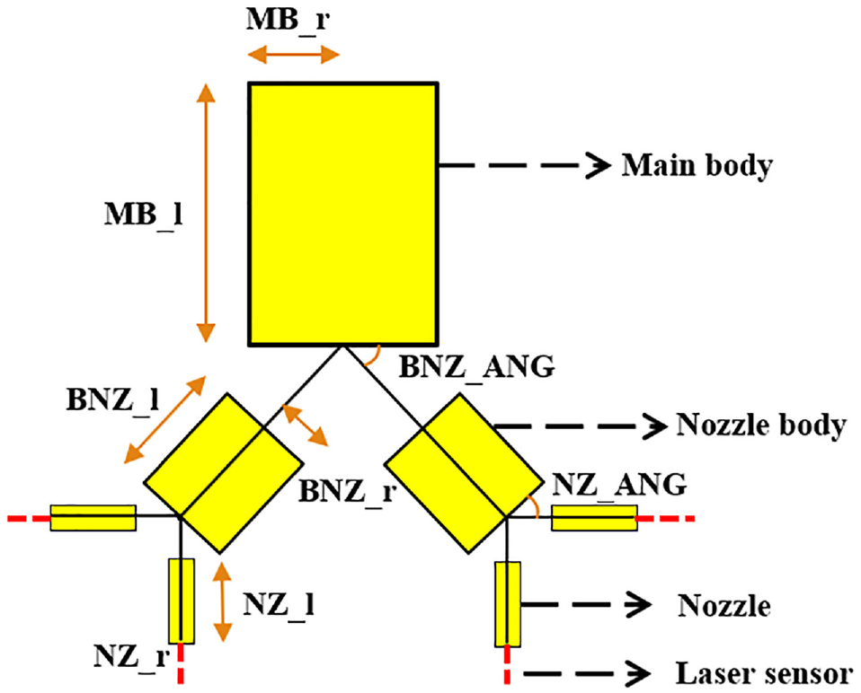
Design variables of waterjet system.
Details of design variables.
“MB_r” and “MB_l” are the radius and length of the main body, respectively. These are not directly related to the pattern of the waterjet. However, these are selected as the design variables because it relates to the start point of the waterjet drive and the installation point of the waterjet body. “BNZ_NO” and “BNZ_ANG” are the variables related to the nozzle body located under the main body. Each means the number of nozzle bodies and the angle between the main body and nozzle body. “BNZ_l” and “BNZ_r” denote the length and radius of the nozzle body, respectively. “NZ_NO” indicates the number of nozzles attached to the nozzle body and injecting the fluid, and “NZ_ANG” indicates the angle of the nozzle to the nozzle body. “NZ_r” and “NZ_l” represent the radius and angle of the nozzle, respectively. In addition, there is a gear ratio, which is a design variable for optimizing the cleaning pattern. This is applied in the form of a coupler to the multi-body dynamics analysis model mentioned below.
Multi-body dynamics model
RecurDyn, a commercial dynamics analysis software, was used for multibody dynamics analysis modeling. 14 The low pressure water jet has various shapes, and the values of the design variable, such as the number of nozzle bodies and the number of nozzles, are changed. For example, a multi-body dynamics model for a model with two nozzle bodies is shown in Figure 8. It consists of one translational joint that allows the entire body to move while the waterjet is running (TRAN), one revolute joint that simulates the rotation of the impeller (RVLT 1), one revolute joint that simulates the output of the planetary gear (RVLT 2), and two revolute joints that delivers the torque form the planetary gear to the nozzle body (RVLT 3, 4). The relationship between revolute joints was applied by using RecurDyn coupler function shown in Figure 9. It connects the two revolute joints, and allows the joint to rotate with the gear ratio set by the designer. There are one gear ratio between the impeller and the planetary gear and two gear ratio between the planetary and the bevel gear. The total number of couplers is three. Based on the example model, the number of nozzles attached to the nozzle bodies is four.
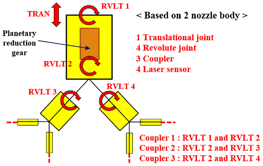
Schematic model of multibody analysis model.
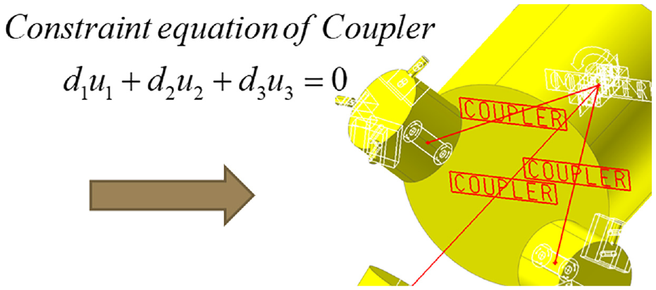
Design of gear train using coupler function for waterjet driving system.
Additionally, a laser sensor was attached per nozzle in the direction of the nozzle length. The laser sensor is a function of RecurDyn. If designer selects the surface of the target structure, designer can detect the points that attack the target structure using this function. The function of the laser sensor is defined by the following equation (2) and Figure 10.

where,

Kinematic model of sensor detected point.
RecurDyn/ProcessNet
In order to reduce the design time by integrating the cleaning pattern design process, RecurDyn/ProcessNet was used. ProcessNet is a toolkit for Macro functions using C# code, it allows a user to create various application codes.15,16
The flow chart of the RecurDyn/ProcessNet code for automating waterjet modeling is shown in Figure 11. It consists of “F1_PV_Gen(),”“F2_Waterjet(),”“F3_DeleteAll().” First, “F1_PV_Gen()” is a function to generate the design variables. It allows designer to apply the design variable values with simple execution without having to input parametric value in RecurDyn. And Next, “F2_Waterjet()’ is the main function that automatically generates the bodies, joints, couplers, expressions(driving constraints), and laser sensors that constitute the low pressure waterjet. Finally, “F3_DeleteAll()” removes all the elements created in the “F2_Waterjet” process. It reduces errors that occur when re-running the automation program. Using these three functions, it is possible to perform continuous analysis automatically as the change of the design variable. It can be used in the optimum design process.

Flow chart of the water jet modeling automation program.
Some of the important design codes are summarized as follows.
1) Creating and applying parametric values

This is the code that automatically generates the parametric value in RecurDyn. If a design variable is created as a parametric value with some value specified by the designer, the shape of the waterjet changes according to the value of the design variable.
2) Define target structure

This is the process of loading the target structure before creating the waterjet model. If the 3D cad file name of the desired target structure is written in the code, the geometry of the target structure will be automatically imported in RecurDyn model. And “model.GetEntity” command allows the designer to select the desired surface by setting the particular surface.
3) Define main body

This code inputs the geometry of the main body, joint, and motion. “IReferenceFrame” command defines the reference frame in which the model will be generated. The body is created via the “model.CreateBody” command, and joints are attached to constrain the bodies through “IJoint” command. To add some driving constraints in the joints, the motion is input through the “IExpression” command.
4) Define coupler

The waterjet has a mechanism that the torque transmitted from the rotor to the planetary gear, and from the planetary gear to the bevel gear. In this process, the coupler function is used to apply the gear ratio. If the designer inputs the desired gear ratio as a value, it is automatically applied when the coupler is created in RecurDyn.
5) Define nozzle body and nozzle

The number of nozzle bodies and nozzles varies depending on the purpose of the waterjet. “fn_Rot2()” function is used to automatically create the nozzle body and the nozzle at the appropriate position. It is calculated by obtaining the transformation matrix using equation (3) and substituting it into equation (4). 17
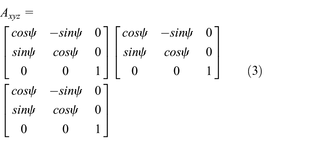

The results of the modeling automation according to the change of the number of nozzle bodies and the number of nozzles are shown in Figure 12.
6) Define laser sensor


Result of changing design variable with regard to nozzle body.
This is the code that generates the laser sensor to perform the analysis on the cleaning pattern. By attaching a laser sensor to the nozzle, designer can check the attack points created on the target surface. It is a method of extracting the coordinate data of the attack points by synchronizing the surface of the imported target structure with the laser sensor. The extracted data is saved as a request file through the “IRequestExpression” command so that it can be used in pattern evaluation process.
Using the automation program, the cleaning pattern results are automatically generated according to changes in the design variables. In addition, coordinate data of the attack points can be extracted from any 3D CAD model of the target structure.
Cleaning pattern evaluation program
In the next step, in order to visually confirm the shape of the pattern according to the change of the design variables, MATLAB 18 was used as shown in Figure 13. Implementing the evaluation program inside RecurDyn/ProcessNet makes it difficult to perform the desired numerical work because the data must be utilized within the RecurDyn interface. In addition to confirming the pattern shape visually, the evaluation method also changes the efficiency of the evaluation standard depending on the structure of the specific shape. Using numerically constructed functions, such as built-in functions or toolkits of the MATLAB, it has the advantage of broadening the spectrum of post-processing methods for the resulting data.

Pattern visualization using MATLAB interface.
The data extracted by the laser sensor using an automation program is used as coordinates x, y, z in 3-dimensional coordinates. When ProcessNet is executed, the coordinates of the detected point are automatically stored in the Request File format. When the stored data is imported into MATLAB and displayed on 3D coordinates, the detection points are drawn in a space – in real time.
In order to verify the usability of the developed program, a cement mixer model and a cylindrical structure model were analyzed. As shown in Figure 14, the cement mixer model is used in 3D CAD model of geometry attached to an actual cement mixer truck, and the cylinder model is used in the 3D CAD model of the geometry of a storage tank. If each 3D CAD model is located in the path of RecurDyn / ProcessNet and the specific surface of the geometry is selected, the attack point data is extracted according to the time domain. Using MATLAB code, the extracted data is visualized in real time and the final result of the cleaning pattern is shown in Figure 15. Through the pattern result, the evaluation can be performed by confirming the surfaces that are not attacked in 3 dimensional space and modifying the design variable values according to the shape of the structure.

Geometry of cement mixer model (left) and cylinder model (right)
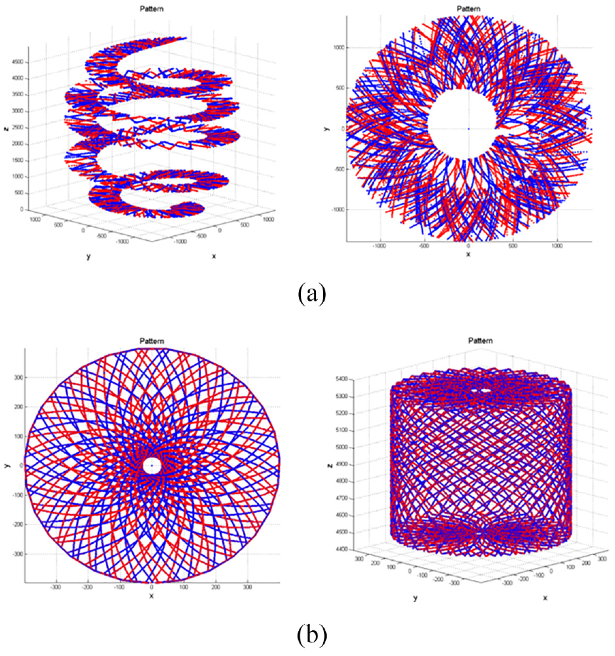
Results of pattern analysis for cement mixer model and cylinder model – in real time: (a) cement mixer model and (b) cylindrical model.
In addition, in order to confirm the pattern controllability, an evaluation was performed by taking a cylindrical structure as an example. The cleaning pattern appears when the values of the nozzle body angle and nozzle angle are changed using the developed program. The results are shown in Figure 16. The results of changing the angle of the nozzle body to 10°, 20°, and 30° (Figure 16(a)) and changing the nozzle angles to 10°, 20°, and 30° (Figure 16(b)) show that the attacked area changes with respect to the upper and lower ends. In the condition that the nozzle angle exceeds 40°, the cleaning area with respect to the longitudinal direction changes up and down at equal intervals. Therefore, it is possible to control the pattern shape of the cylindrical structure in the longitudinal direction (Figure 16(c)). If the nozzle body angle and the nozzle angle are simultaneously considered, it is possible to strike the specific region asymmetrically up and down, and the pattern can be controlled by considering the specific region (Figure 16(d)). The analysis results indicate that the cleaning pattern can be derived that the waterjet attacks only a specific area according to the design purpose.

Pattern result according to change of design variables (nozzle body angle, nozzle angle): (a) change of BNZ_ANG from top view, (b) change of NZ_ANG from top view, (c) change of NZ_ANG from side view, and (d) change of BNZ_ANG, NZ_ANG from side view
Analysis and evaluation of cylindrical structure
Analysis method of cylindrical structure
The previously developed program is a method of visualizing the cleaning pattern through attack points where contact with the structure occurs. However, As shown in Figure 17, when the actual water jet is sprayed, a circular attack area is generated. Therefore, using only attack points has a limitation in simulating actual attack areas. To overcome this problem, it is advantageous to simulate the actual phenomena accurately by performing the flow analysis. 19 However, it is inefficient since the analysis time increases. Above all, the problem of waterjet cleaning patterns is not suitable for performing the flow analysis because it is the main purpose to evaluate whether the change of the kinematic pattern according to the design variables covers a large area in a short time. Therefore, this study devised a numerical pattern analysis method to evaluate the pattern. The method can shorten the design time, which is a disadvantage of the flow analysis, and simulate the actual phenomenon effectively.

Actual attack area of waterjet.
The cylindrical structure was analyzed using a structure with a diameter of 420 mm and a length of 840 mm. The analysis method is as follows.
(1) The coordinate value data (x, y, z) of the impact point on the cylindrical structure is extracted through the developed program.
(2) As shown in Figure 18, a cylindrical structure is divided into a side area and a circle area (top and bottom area). Converts the three-dimensional data from the Cartesian coordinate to the polar coordinate, and then converts it into the 2-dimensional data using equation (5).

(3) Using the transformed data, a zero matrices with the same size as the side area and top and bottom area are created. It is shown in Figure 19.
(4) To apply the circular attack area, each time the attack point is created, the matrix value inside the attack radius (
(5) If the analysis is performed through this method, the cumulative attack area over time can be confirmed in real time (Figure 21). However, this method generates the circle area even beyond the boundary of the actual area, and therefore, deletion of the additional area is required (Figure 22).
(6) If the analysis is performed until the waterjet is driven for 1 cycle, a matrix corresponding to the area of the cylindrical structure is finally obtained. Each time the same area is attacked again, the matrix value increases by 1. By checking the value of the final matrix, designer can check how many times the same point is attacked. Figure 23 shows the attack area according to the attack times.
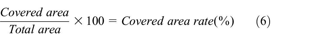
(7) Since the area of the upper and lower surface of the structure and the area of the side surface are fixed, it is possible to calculate the attack area per the total area. In this paper, it is presented as an evaluation criterion of the waterjet performance. And it is defined as the covered area rate and shown in equation (6). It can be used as an objective function for the optimum design of water cleaning pattern.

Attack point extraction using developed program.

Save attack points using matrix with regard to particular time.

Increase the matrix value corresponding circle area by one for each additional time.

Convert simple data set of attack points into attack area with circular shape.

Delete unnecessary data to fit top and bottom circle area of cylindrical structure.

Check attack area according to the change of attack times.
Analysis results of cylindrical structure
The covered rate analysis was performed according to the analysis method of the cylindrical structure. The analysis conditions were six kinds of analysis by combining the nozzle angle and the bevel gear ratio, and attack circle radius set is 15 mm. It is shown in Table 2. Figure 24 shows the results of the analysis performed under conditions of 50:49 and nozzle angle 0°. The number of attacks according to the time can be confirmed by the applied analysis method. Covered area represents the area that has attacked at least once, that is, a matrix value of one or more. The overlap area means inefficiency when one or more attacks occur. In this analysis, the side area of the cylindrical structure is set to a reference matrix value of 15 or more, and the area of the circle area is set to a reference matrix value of 10 or more. Since the size of the circle area is smaller than side area, many overlapping attacks occur at the circle area, relatively. Therefore, the reference matrix values of the overlap area are different in order to effectively confirm the results of the change of the design variables. Tables 3 and 4 show the results of the analysis performed according to the six analysis conditions.
Analysis conditions.


Result of pattern analysis with gear ratio 50:49 and nozzle angle 0°.
Covered area rate and overlap area rate of circle area.

Overlap area conditions: over 10 times.
Covered area rate and overlap area rate of side area.
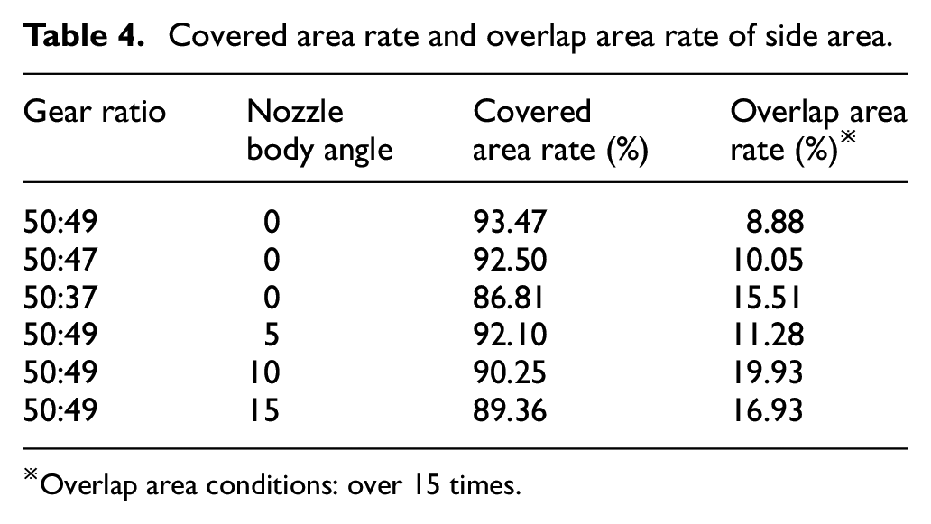
Overlap area conditions: over 15 times.
According to the analysis results, the combination of 50:49 and 0° in the side area has the highest covered area ratio of 93.47%. In addition, Overlap area is also the smallest in this combination with 8.88%. On the other hand, in the circle area, the area covered area ratio was the highest with a combination of 50:49 and 5°, 97.71%. This is because the nozzle angle of 5° can attack the center of the circle area where the 0° nozzle angle model cannot attack. The overlap area ratio was the lowest at 68.79% in the combination of 50:49 and 37°, but the efficiency was not good because the covered area rate was 93.93%.
The water jet injection pressure depends on the adhesion and strength of the attachment to be removed, and the distance between the waterjet and the structure. The attack radius (

Comparison of covered area rate according to attack diameter and time flow.
The 1 cycle was selected based on case 1 which is a combination of 50:49 and 0°. 1 cycle takes 4.9201 s, and the analysis is performed for each the side area and the circle area. When the attack radius is set to 15 mm, the covered area rate of case 2 is higher than case 1 until 4/6 cycle on the side area, but the covered area rate of case 1 is higher than case 2 when 1 cycle is finished. When the attack radius is set to 25 mm, the covered area rate of case 2 and case 3 is the higher than the others until 5/6 cycle on the side area, and the covered area rate of case 2 is the higher than the others until 4/6 cycle on the circle area. In addition, if the attack radius is increased to 35 mm, case 2 and case 3 already have a covered area rate of more than 95% at the 4/6 cycle point. These results show that the optimum waterjet model can be changed according to the change of the attack radius satisfying the design purpose. Furthermore, it has the potential to reduce the operation time according to the percentage of the final covered area required by the user.
As a result of the analysis, it was confirmed that the optimum design variable value depends on the target structure of the waterjet cleaning pattern. If a user purchases a waterjet of a different shape every time a target structure is changed, it incurs unnecessary cost. When the design variable of the waterjet is changed, the shape of the nozzle body part is changed but it does not affect the shape of the input part and the stem part. Using these structural characteristics, as shown in Figure 26, the nozzle body part can be separated and replaced. In addition, when the nozzle is designed to be detachable, it is possible to easily change the nozzle size or the number of nozzles, and thereby, the pressure of the attack can be controlled. In this study, the product that applied these improvements was named as the module type waterjet. The idea was made as a prototype as shown in Figure 27. The driving performance test has been completed and the idea was patented in Korea in May 2018.

Idea of module type waterjet.

Prototype model of module type waterjet.
Conclusion
The modeling process was automated only by changing the design variables using RecurDyn/ProcessNet, and the simulation technique was used to describe the waterjet cleaning phenomenon for the specific shape through the laser sensor function. Based on the extracted 3D coordinate points, the cleaning pattern visualization program was developed. As a result, design time and cost are reduced according to the change of the design variables. The usefulness of the program was verified through an example of a cylindrical structure. In this process, numerical techniques for cylindrical structures with low pressure water jet are developed and evaluation criteria that can be used for optimum design are presented. The effect of changes in design variables on the covered area rate was analyzed, and the efficiency of the work with overlap area rate was analyzed.
The originality of this study is summarized below based on the research results.
- Design program that can automate the generation of waterjet analysis models is developed only by changing the design variables.
- Through the analysis of the cleaning pattern according to the change of the design variables, the controllability of the specific area is confirmed.
- Using numerical techniques, a cleaning pattern analysis method for cylindrical structures was developed.
- The analysis of pattern efficiency according to time has been carried out and the improvement guideline was suggested.
- The idea of a module type waterjet was presented to reduce the unnecessary cost of changing the target structure.
In order to effectively apply the developed program to the actual waterjet industry and apply it to various industries, there are limitations and will be resolved through future research.
The purpose of the low-pressure water jet for cleaning is to check the cleaning pattern, calculate the area that can be covered for cleaning, and evaluate whether it is possible to cover the entire area. However, in order to apply the developed program to a waterjet intended for crushing or cutting, a function to analyze it must be added. Therefore, in order to simulate this, the program will be improved by adding a theoretical formula that can simulate the attack (or impact) force and attack area according to the pressure of the water jet. 20 Furthermore, in order to secure the reliability of the prediction program for calculating the impact force, the sensitivity of design variables will be analyzed by testing and evaluating the actual impact force of the waterjet. 21 Finally, a program that can suggest efficient design approaches to various industries as well as the cleaning waterjet industry will be developed.
Footnotes
Handling Editor: James Baldwin
Declaration of conflicting interests
The author(s) declared no potential conflicts of interest with respect to the research, authorship, and/or publication of this article.
Funding
The author(s) disclosed receipt of the following financial support for the research, authorship, and/or publication of this article: This work was supported by Korea Institute of Industrial Technology (KITECH) and Pusan National University Research Fund.