
Abstract
The camber and cornering properties of the tire directly affect the handling stability of vehicles, especially in emergencies such as high-speed cornering and obstacle avoidance. The structural and load-bearing mode of non-pneumatic mechanical elastic (ME) wheel determine that the mechanical properties of ME wheel will change when different combinations of hinge length and distribution number are adopted. The camber and cornering properties of ME wheel with different hinge lengths and distributions were studied by combining finite element method (FEM) with neural network theory. A ME wheel back propagation (BP) neural network model was established, and the additional momentum method and adaptive learning rate method were utilized to improve BP algorithm. The learning ability and generalization ability of the network model were verified by comparing the output values with the actual input values. The camber and cornering properties of ME wheel were analyzed when the hinge length and distribution changed. The results showed the variation of lateral force and aligning torque of different wheel structures under the combined conditions, and also provided guidance for the matching of wheel and vehicle performance.
Keywords
Introduction
The development of automobile industry greatly driven the growth of tire industry. However, with the continuous improvement of people’s requirements for safety, handling and comfort when driving a car, the performance matching requirements of the tire and the whole vehicle are increasingly strict, especially the safety performance of the tire. There are many risk factors such as puncturing, deflating and blowout in the driving process of vehicles equipped with traditional pneumatic tires.1,2 Therefore, it is an important research trend to develop a safe, comfortable and economic safety tire.
Generally, there are two main factors required for a safety tire. First, in non-emergency situations, various performance indicators of the safety tire, including the vehicle’s handling stability, comfort and smoothness, can meet or exceed those of traditional pneumatic tires. Second, when encountering dangerous situations such as nailing or flat tires, vehicles equipped with safety tires can continue to drive steadily. According to the applied technical means, safety tires mainly include self-supporting tires, inner-supporting tires, self-sealing tires and non-pneumatic tires.3–5 Many researchers have studied the characteristics of different types of safety tires, but so far, the application of safety tires is still limited to a few special vehicles and some advanced passenger vehicles.6–8 With 3D printing technology, Kannan et al. 9 analyzed the static and load-carrying characteristics of honeycomb non-pneumatic tires with different spoke angles and materials. Zang et al. 1 studied the steady-state temperature field characteristics of an inner-supporting tire, and optimized the inner support structure by the thermal mechanical coupling method. To reduce the rolling resistance of a non-pneumatic tire, a porous elastomer shear band was explored by Ju et al. 10 and the reduced energy loss was also quantified by FEM. The aerodynamic flow of a flexible spoke non-pneumatic tire was analyzed by Huang et al. 11 using the Reynolds-Averaged Navier-Stokes method and Large-Eddy simulation, and an optimization scheme to improve the aerodynamic noise performance was proposed.
The ME wheel studied in this work is a non-pneumatic safety tire with a suspension hinge structure, which has the advantages of puncture resistance, low rolling resistance and high comfort. 12 In addition, the amount of rubber material required for ME wheel is reduced by about one third compared with the traditional inflatable tire. Therefore, the ME wheel also has significant advantages in terms of cost savings and environmental protection. Zhao et al. 13 investigated the ME wheel with different hinge structure and distribution, and compared the stiffness properties of ME wheel with those of an inflatable tire. Based on the technology of virtual proving ground, Xiao et al. 14 analyzed and predicted the service life of the ME wheel, and carried out multi-objective optimization design.
Tire mechanics is an important part of vehicle dynamics and control research, and its research methods can be generally divided into theoretical methods and experimental methods. However, with the development of computing technique, the research methods of tire mechanics are diversified.15–17 Yu et al. 18 developed a theoretical three-dimensional ring based model and a new displacement function to investigate the lateral and radial vibration characteristics of tire. The proposed model and displacement function were confirmed to be efficient and reliable by tests. Veeramurthy et al. 19 used FEM to study the influence of geometry and material parameters on tire performance, and optimized the tire in combination with the generated response surface model. Zhang et al. 20 proposed a beam-spring network model to investigate the stick-slip interactions between the tire and road, and the developed modeling method was validated by embedding the tire force sensors into the rubber layer and conducting tests. For the sake of improving the smoothness and service life of the run-flat tire, Cho et al. 21 introduced a multi-objective optimization method to adjust the shape and stiffness of sidewall rubber, and confirmed the rationality and effectiveness of the optimization method by numerical experiments.
Neural network is the mainstream of non-linear science and computational intelligence science. It is good at classifying and discovering its laws through large amounts of data, and can approach any non-linear function, with advantages of self-organization, self-adaptive, associative memory, high fault tolerance and parallel processing ability. 22 To estimate the friction force between the tire and the road, Matuško et al. 23 developed a neural network based estimation scheme. Through the simulation of one-wheel friction model, the proposed estimator was proved to be able to estimate friction rapidly and accurately. Zhang et al.24,25 used the combination of FEM and neural network to established a tire-ice traction model, which can predict the traction performance of the tire on the ice very well. Additionally, the Levenberg-Marquardt algorithm was also used to predict the friction between the tire and ice. For the optimal solution of multiple peaks, Nakajima et al. 26 developed an optimization method on the basis of neural network, and applied it to the optimization of tire performance, which greatly saved the calculation cost. Pramono et al. 27 used BP neural network to predict the performance of airless tire with different structure and material parameters, and optimized the tire structure by combining genetic algorithms.
The main purpose of this work is to study the influence of hinge length and distribution number on the camber and cornering properties of ME wheel by using the method of combining FEM and neural network model. The overall structure of this work is as follows. In section “ME wheel structure,” the main composition structure of the ME wheel and its load-carrying characteristics are introduced. The BP neural network structure and algorithm derivation are presented in section “BP Neural network model theory”. The establishment and verification of the finite element simulation model of the ME wheel are shown in section “Numerical simulation modeling”. Then, in section “Neural network model of ME wheel,” the modeling approach of the neural network model of ME wheel is illustrated. In section “Results and discussion,” the predicted camber and cornering properties of ME wheel with different hinge lengths and distributions are discussed. Finally, the main conclusions are summarized in section “Conclusion.”
ME wheel structure
The ME wheel was designed for the reason that a certain type of special vehicle was vulnerable to puncture and tire burst in the process of operation, which makes the vehicle lose its mobility. It is mainly composed of flexible tire body, suspension hub, return springs and several hinge groups evenly distributed along the wheel circumference, as shown in Figure 1. The ME wheel adopts a suspension bearing design, and the hinge groups near the grounding area will bend due to the deformation of the flexible tire body when an axial load is applied to the wheel.

Main composition structure of ME wheel.
The structural characteristics and bearing form of the ME wheel determine that the mechanical properties of the ME wheel will be changed when different combinations of hinge length and distribution number are adopted, as shown in Figure 2. The research on the influence of the length and distribution of the hinge group on the camber and cornering properties will help to better meet the vehicle’s matching requirements for wheel performance and the subsequent optimization of the wheel structure.

Examples of ME wheel with different hinge lengths and distributions.
BP Neural network model theory
Neural network structure
BP neural network is a multilayer feedforward neural network, which consists of input layer, hidden layer and output layer. In the structure of BP network, each layer of neurons can only accept the input of the previous layer of neurons. As shown in Figure 3, a typical three-layer structure of BP network is displayed, and the input node and output node number are m and n, respectively. Additionally,

BP neural network structure.
BP learning algorithm and derivation
BP algorithm divides the entire learning process into forward propagation process and back propagation process. In the first phase, the input data is input from the input layer and the output data of each unit is computed layer by layer through the hidden layer. The second phase is the back propagation process. If the output layer does not get the expected result, the error between the obtained value and the expected value will be calculated, and then the weight of the previous layer is corrected based on the error to reduce the error signal.
In the process of network learning, assuming that there are N training samples in total, select one sample to train it, then the output of the hidden layer node is written as
where
The actual output

The error function
where
The gradient of

In equation (4), only

Then, equation (4) is further derived as

where
In order to keep the error decreasing, the adjustment should be made along the negative gradient direction of the weight, and the correction is as follows

where

where
When the weight value is corrected, the threshold

The corrections for thresholds

The corrected thresholds are
Based on the above derivation process, input all training samples repeatedly during training, and stop network training when the total error of training samples meets the set requirements or reaches the maximum set network training times.
Numerical simulation modeling
In order to reduce the test cost, the numerical simulation results of ME wheel in multiple working conditions are selected as training samples in the course of network learning, and the finite element numerical simulation model of the ME wheel needs to be established and verified. In the simulation analysis, different hinge lengths and distribution numbers cannot be realized by setting the boundary conditions of the finite element model, but can only be achieved by establishing the finite element models of ME wheel with different hinge lengths and distribution numbers. Therefore, four combinations (A1, A2, B1 and B2) of different hinge lengths and distribution numbers were randomly selected during the finite element modeling of the ME wheel. Figure 4 displays the finite element modeling process of ME wheel with ABAQUS software.
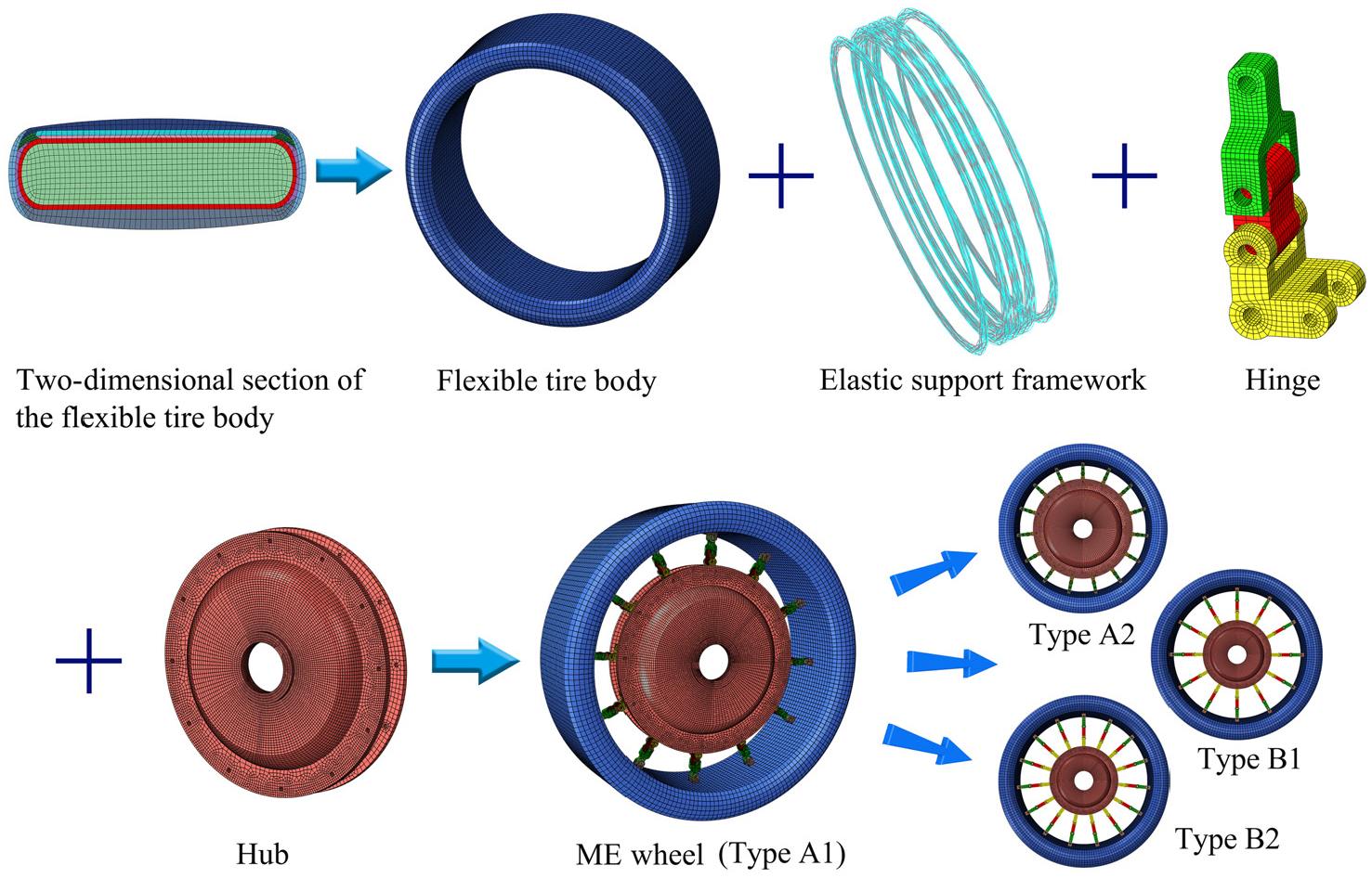
Finite element modeling process of ME wheel.
The cord layer and belt layer in the flexible tire body of ME wheel belong to rubber-cord composite, and their properties show obvious anisotropy. Generally, the modeling methods of rubber-cord composite mainly include laminated shell model and rebar model. In the laminated shell model, the orthotropic material parameters of each layer are obtained by simple mixing formula. The rubber matrix and cord can only be simulated as linear elastic material, ignoring the nonlinearity of rubber and the double modulus property of cord, which will lead to the decrease of calculation accuracy. In the rebar model, the stiffener element and solid element are used to represent the stiffener structure and matrix structure of the composite, and the matrix and stiffener are expressed by different constitutive relations. Therefore, the rebar model was adopted to simulate the rubber-cord composite of the ME wheel in this paper. The suspension hub, hinge group and flexible tire body were all simulated by linear reduced integral elements C3D8R, and the elastic support framework inside the flexible tire body was modeled by beam elements B31. The hinge groups were connected to the suspension hub and the flexible tire body by defining hinge constraints. The material parameters of ME wheel used in the modeling process and their acquisition methods are shown in Du et al. 28
To verify the reliability of the FEM model of the wheel, the bench tests of A2-type and B1-type wheels were carried out respectively. Figure 5(a) shows the test and simulation values of wheel sinkage when the wheels were subjected to different vertical loads, and Figure 5(b) shows the test and simulation values of lateral offset under different lateral forces when the vertical load was 10000 N. It can be seen that the change trends of the test data and the simulation data are basically the same, which indicates that the established simulation model of ME wheel has high accuracy and can be used for follow-up research.

Comparison of bench test results and simulation results of ME wheel: (a) wheel sinkage and (b) lateral offset.
Neural network model of ME wheel
Model establishment
The main purpose of establishing ME wheel neural network model in this section was to use the generalization ability to analyze the influence of the length and circumferential distribution of hinges on the camber and cornering properties of ME wheel. Therefore, the vertical load, the number of hinge groups, the hinge length, the camber angle, and the slip angle were selected as the five neurons of the input layer. The output layer contained two neurons, namely, the lateral force and the aligning torque. A three-layer BP neural network can approximate the function in the range of less than any square error. Therefore, the hidden layer number of the model was selected as one layer, and the hidden layer nodes was determined to be 17 by the combination of empirical formula and trial and error method. The established ME wheel neural network model of 5-17-2 structure is shown in Figure 6.

BP neural network model of ME wheel.
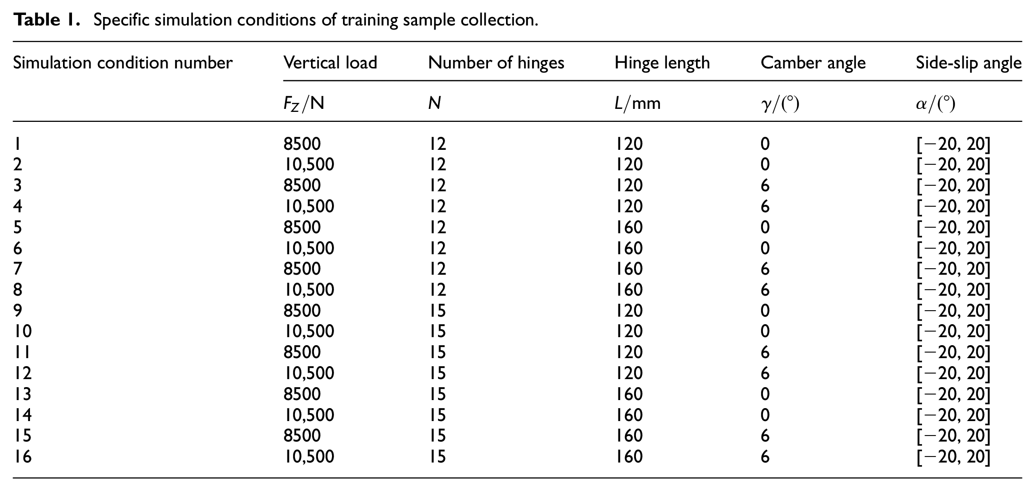
The training samples of the established network model are the numerical simulation results of ME wheel under 16 combined working conditions of camber and cornering. The specific collection conditions of the samples are shown in Table 1, and the selected samples contain 336 groups of data, as shown in Figures 7 and 8. Among these data samples, 21 groups of data of condition 16 were used as the verification samples of the generalization ability of the network model, and were not participate in the training. The sigmoid function was used as the transfer function between the input and output of each layer in the network model, and the control error was 10−3.
Specific simulation conditions of training sample collection.

Lateral force under 16 simulated conditions.

Aligning torque under 16 simulated conditions.
Neural network can process data from different sources, but it can only process data with a certain format, and the format of data has an important impact on the convergence speed and network performance. Therefore, the training sample data should be normalized before network training. The normalization equation selected in this study is described as below
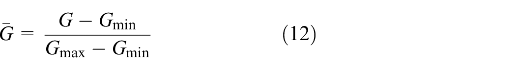
where
Algorithm improvement
The derivation process of BP algorithm is rigorous, with high precision and strong universality. However, the general BP algorithm has a slow convergence rate and is prone to fall into local minimums. In view of the above shortcomings, the additional momentum term and the adaptive learning rate were used to improve the standard algorithm.
The additional momentum enables the network to include the influence of the error on the gradient and the effect of the change on the error surface when modifying the weights. A value proportional to the previous weight change is added to each weight change, and a new weight change is generated according to the back propagation method. The formula for adjusting the weight of additional momentum terms can be expressed as

where
In the learning process of BP network, the selection of learning rate should not be too large or too small. Excessive learning rate will cause the network to oscillate or diverge during training, while small learning rate will reduce the convergence speed of training. The basic assumption of the adaptive learning rate is that the learning rate can be adjusted adaptively according to the error change. The learning rate adaptive mechanism used in the training is shown in equation (14).
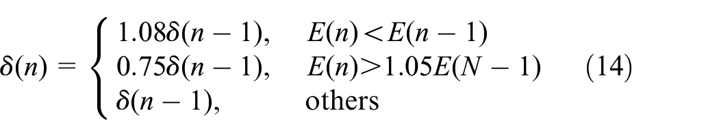
where
Validation of neural network model
It is necessary to verify the learning ability and generalization ability of the model after the network training. Figure 9 shows the relation curve between the number of iterations and training error in the network training process. After 1735 iterations, the required accuracy was achieved and the iteration was terminated. Taking the sample points of the training as input, the comparison between the output data and actual input data can be used as the verification of learning ability; taking the sample points that were not participating in the training as input, the comparison between the output data and the actual input data can be used to validate the generalization ability of the network model.
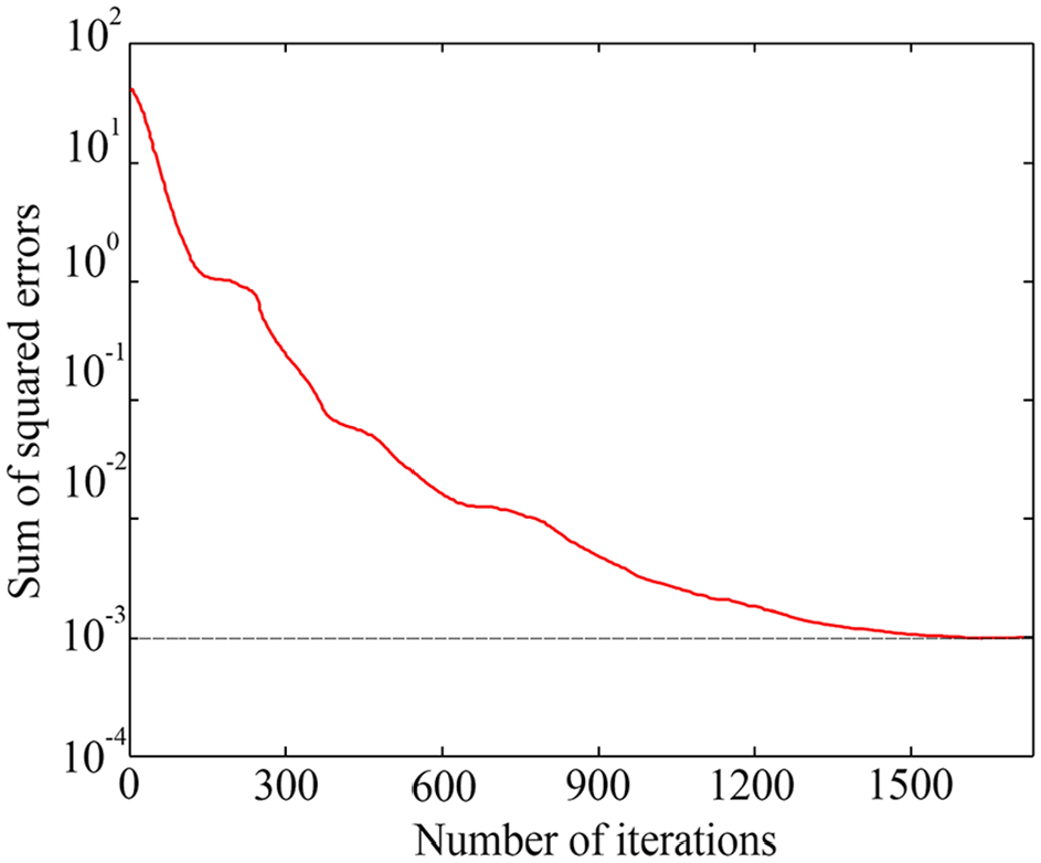
The change curve of training error in the process of network training.
Take the relationship between input and output in condition 1 and condition 4 as an example to analyze and verify the learning ability of the network model. Under these two conditions, the comparison between the lateral force characteristic curve of the model output and the actual input value of learning sample is shown in Figure 10(a), and the comparison between the aligning torque characteristic curve and the learning sample is shown in Figure 10(b). It is easy to see that the output characteristic curves of the network model have a high degree of coincidence with the sample points, thus verifying the learning ability of ME wheel network model.

Comparison between the actual input value and the output value of training samples: (a) lateral force comparison and (b) aligning torque comparison.
Figure 11 shows the comparison between the untrained sample points of condition 16 and the lateral force and aligning torque characteristic curves obtained by the generalization ability of the network model. It can be seen that the predicted values and the actual input values still have good consistency. Therefore, the established ME wheel neural network model has remarkable generalization for untrained samples and has high prediction accuracy.

Comparison between the actual input value of non-training samples and the generalization curves: (a) lateral force comparison and (b) aligning torque comparison.
Results and discussion
Influence of hinge length on camber and cornering properties
In the last section, the learning ability and generalization ability of the established ME wheel neural network model were verified by comparing the input and output characteristics of the training samples and non-training samples. It is proved that the neural network model has high accuracy in the prediction of the camber and cornering properties of the ME wheel. Therefore, after changing the input of the network model, the influence of the change of the input term on the camber and cornering properties of the ME wheel can be quickly obtained by using the generalization ability of the model. In this section, under the condition of keeping the vertical load
Figure 12 displays the change curves of the lateral force characteristics of the ME wheel when matching different hinge lengths. It can be seen that the change trend of the lateral force of the ME wheel is basically the same when the length of hinge group is different. Furthermore, in the case of the same side-slip angle, the increase of hinge length will lead to the decrease of lateral force. However, when the side-slip angle is large, the influence of hinge length on the lateral force characteristics is not significant.

The lateral force of ME wheel with different hinge length.
The variation curve of the aligning torque characteristics for different hinge lengths is displayed in Figure 13. Compared with the curve features in Figure 13, it is obvious that the change trend of the aligning torque is also basically the same when the length of hinge groups is different, but the value of the aligning torque corresponding to the same side-slip angle gradually increases with the increase of the length of hinge groups.

The aligning torque of ME wheel with different hinge length.
Influence of hinge distribution on the camber and cornering properties
In the case of keeping the input items of wheel vertical load, hinge length, camber angle and side-slip angle unchanged, the influence of different hinge distribution on the lateral force and aligning torque under the combined condition of camber and cornering is shown in Figures 14 and 15, respectively. By comparing the characteristic curves of the lateral force and the aligning torque of different hinge distribution, it is easy to see that when the side-slip angle is constant, increasing the hinge number will increase the lateral force of the ME wheel, but the aligning torque will decrease. In addition, in the case of large side-slip angle, the influence of hinge distribution on lateral force and aligning torque will be weakened.

The lateral force of ME wheel with different hinge distribution.

The aligning torque of ME wheel with different hinge distribution.
It can be seen from the above analysis that changing the length or distribution number of the hinge groups can make the ME wheel have different camber and cornering properties. Therefore, the length and distribution number of hinge groups can be reasonable adjusted or combined according to the actual needs, so that the matching requirements of the vehicle to the wheel performance can be better satisfied. In addition, the camber and cornering properties of different wheel structures obtained by the generalization ability of the network model can be an important theoretical basis for subsequent wheel structure optimization.
Conclusion
Based on the ability of neural network to arbitrarily approximate any nonlinear mapping, a neural network model of ME wheel was established in this paper, and the camber and cornering properties of ME-Wheel with different wheel structures were analyzed by using the generalization ability of the model. The main conclusions are summarized as follows:
The established three-layer neural network model of ME wheel, which takes the vertical load, the hinge length, the number of hinge groups, the camber angle and the side-slip angle as the input layer neurons and the lateral force and the aligning torque as the output layer neurons, has good learning ability and generalization ability.
The additional momentum term and the adaptive learning rate have a good effect on the improvement of the slow convergence rate and easy to sink into the local extremum of BP algorithm.
Under the condition of keeping the vertical load, camber angle and side-slip angle constant, the lateral force of ME wheel decreases with the increase of the hinge length, and increases with the increase of the distribution number of hinge group. The aligning torque increases with the length of hinge group and decreases with the distribution number of hinge group. However, in the case of large side-slip angle, the influence of the length and number of hinge groups on the lateral force and aligning torque is weakened.
This research provides an important basis for the optimization of wheel structure and better performance matching between wheel and vehicle. More importantly, the method also provides a new way for the research of mechanical characteristics of ME wheel, which can be further applied in the follow-up research.
Footnotes
Handling Editor: James Baldwin
Declaration of conflicting interests
The author(s) declared no potential conflicts of interest with respect to the research, authorship, and/or publication of this article.
Funding
The author(s) disclosed receipt of the following financial support for the research, authorship, and/or publication of this article: This work was supported by the Scientific Exploration Fund of the General Armament Department of China (No. NHA13002) and the Scientific Research Foundation of Shandong University of Science and Technology for Recruited Talents (No.2019RCJJ015).